Abstract
This article presents a compact tip-tilting platform designed for hardware-in-the-loop emulation of spacecraft relative dynamics and a physical setup for testing tethered systems. The architecture consists of a granite slab supported by a universal joint and two linear actuators to control its orientation. This configuration allows a Floating Spacecraft Simulator to move on the surface in a quasi-frictionless environment under the effect of gravitational acceleration. The architecture includes a dedicated setup to emulate tethered satellite dynamics, providing continuous feedback on the tension along the tether through a mono-axial load cell. By adopting the Buckingham “” theorem, the dynamic similarity is introduced for the ground-based experiment to reproduce the orbital dynamics. Proof-of-concept results demonstrate the testbed’s capability to accurately reproduce the Hill–Clohessy–Wiltshire equations. Moreover, the results of the deployed tethered system dynamics are presented. This paper also details the system architecture of the testbed and the methodologies employed during the experimental campaign.
1. Introduction
Ground-based testbeds play a crucial role in validating spacecraft hardware, software, and operational procedures prior to in-orbit commissioning. By enabling tests in a controlled setting, they help identify potential problems and optimize system performance, thereby reducing mission risks and costs [1,2,3,4,5]. In particular, experimental facilities that reproduce aspects of the space environment are essential for testing orbital dynamics and for validating attitude and orbit control systems [6].
Several approaches exist to emulate microgravity conditions, including drop towers, parabolic flights, and sounding rockets. These provide reduced-gravity environments lasting up to about 10 s, 25 s, and more than 1 min, respectively [7,8,9,10]. Longer-duration microgravity can be achieved in space laboratories, such as those hosted on the International Space Station, and previously on the Space Shuttle before its retirement [10].
As a complementary ground-based solution, air-bearing platforms provide a practical means to emulate microgravity by minimizing friction on a precision-levelled surface [7,11]. These testbeds allow reduced-scale Floating Spacecraft Simulators (FSSs) to reproduce planar motion, and they are widely used to validate Guidance, Navigation, and Control (GN&C) algorithms in proximity operations, formation flying, rendezvous, and docking manoeuvres [12,13,14,15,16].
In this paper, an air-bearing platform for emulating orbital dynamics is presented, building upon the concept proposed by Ogundele et al. [4]. The main novelty of the testbed lies in controlling the attitude of the granite slab, which can be tip-tilted using a pair of linear actuators and a universal joint. This configuration allows the non-actuated FSS to respond to the granite surface inclination with high sensitivity, effectively reproducing accelerations comparable to those experienced by a satellite in orbit.
One of the main advantages of a tip-tilt testbed architecture is its ability to reproduce continuous accelerations on a non-actuated FSS. While continuous forces can also be generated using thrusters with dedicated modulation methods [17,18], a tip-tilting platform achieves this independently of any specific thruster type or control scheme. It can therefore simulate orbital disturbances that act continuously on spacecraft systems. In addition, a passive, non-actuated FSS is lighter and has lower inertia than an actuated one, making it more responsive to changes in table inclination and extending the experiment duration by reducing the consumption of compressed air. The main drawback of this architecture is scalability: as the table size increases, it becomes challenging to identify actuators that satisfy both stroke and frequency requirements. Furthermore, table levelling accuracy is directly constrained by the resolution of the linear actuators, since the smallest achievable step in their extension determines the minimum levelling increment. Finally, a non-actuated FSS on a tip-tilt platform, such as the one presented here, lacks intrinsic attitude control; future developments could include integrating a reaction wheel to provide this functionality. The present work also introduces the integration of a system specifically designed for testing control algorithms oriented to tethered satellite systems. In detail, the Floating Platform is also equipped with a tether, which is connected to a load cell to measure its tension. The load cell is mounted on a vertical support on a linear guide, enabling dynamic simulations of tethered satellite systems during different operational phases. This setup is developed with a different approach with respect to previous research on testing tethered satellite systems on ground-based frictionless tables [19,20,21]. The proposed architecture leverages the capability of a novel tip-tilting facility to reproduce continuous and precise accelerations.
The rest of this paper is organised as follows: The architecture of the testbed is introduced in Section 2, with all of its components and parameters. Subsequently, the mathematical and on-orbit modelling, on which the testbed is based, are described in Section 3. To demonstrate the testbed’s working capabilities, a test campaign is conducted, as described in Section 4. The numerical results of the experimental campaign are presented and discussed in Section 5. Finally, our conclusions are presented in Section 6.
2. System Architecture
This section introduces the testbed, which is subdivided into the following subsystems: the Floating Spacecraft Simulator (FSS), an air-bearing scaled and simplified model that represents the satellite; the Floating Platform (FP), which includes the granite slab, the actuator system, and the laser sensors, standing as the central stage on which the FSS operates; the Motion Capture System (MCS); the Tether Testing System (TTS); and the Master Console (MC). The setup of the testbed is presented in Figure 1.
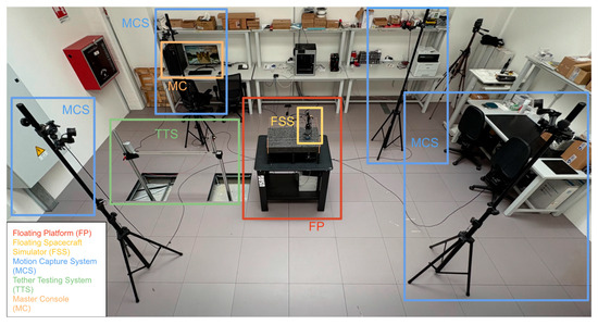
Figure 1.
Laboratory setup. The subsystems of the testbed are framed with the corresponding colours.
2.1. Floating Platform
The FP is shown in Figure 2. It features a polished granite slab (1) tilted by two linear actuators (2). Laser sensors (3) can be used to measure the relative attitude of the granite surface. The proper kinematics of the mechanism is then ensured by one pair of spherical joints, which link the linear actuators to the slab, and a universal joint (4). This setup enables the slab to be tilted around two axes, allowing a rigid body positioned on the granite table to experience a simulated gravitational force.
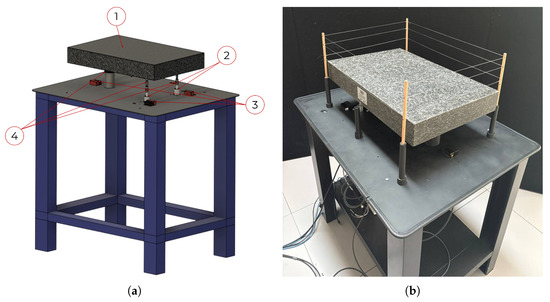
Figure 2.
(a) A 3D model of the Floating Platform (FP) composed by: 1. granite slab, 2. linear actuators, 3. laser sensors, 4. universal and spherical joints. (b) Physical apparatus and actual photo of the FP.
Granite was identified as the most suitable material for the slab, as an extremely flat and smooth surface is required for air-bearing platforms. The granite slab, manufactured by Zali Precision, was polished with high precision, resulting in very low surface roughness and high surface flatness. Moreover, it had great rigidity and high thermal stability. Thus, it would not warp or expand with temperature changes. Furthermore, unlike metal, granite has good damping properties, helping to absorb vibrations and to avoid oscillations.
The linear actuators (LGA56–Captive linear actuator–NEMA 23 by Nanotec) are powered by a power supply unit and actuated via motor controllers (C5-E series by Nanotec), which communicate with the MC via the Modbus TCP protocol. The testbed is also equipped with three laser sensors (optoNCDT-1220 of the Micro-Epsilon series) working in VIS-RF (visible–radio-frequency, red semiconductor laser). Lasers are used to measure the relative displacement of three points on the tilting surface with respect to the reference plane. Those three points can be used to evaluate the attitude of the table. The motors and lasers are placed on a steel base attached to the bottom of the support frame, as shown in Figure 2. The specifics of each equipment are reported below in Table 1. In particular, the step angle is the angular rotation of the motor shaft, while the step resolution is the resulting linear displacement of the actuator. The lead screw is divided by the number of steps per revolution, which is defined by the step angle. Finally, the motor’s step angle sets the rotational precision; together with the lead screw, this determines the actuator’s linear positioning resolution.

Table 1.
Floating Platform components’ properties.
2.2. Floating Spacecraft Simulator
The spacecraft simulator developed at Politecnico di Torino [22] is a revised version of that designed and tested at the Naval Postgraduate School of Monterey [23].
The FSS is characterized by a pneumatic subsystem and an air bearing, as shown in Figure 3. It can move on the monolithic granite slab depending on the adopted control strategy. The structure is composed of a 3D-printed tank container, an air bearing, and a 3D-printed component to fix the tether anchor point, to allow the markers being placed to track the FSS through the optical capture system. The pneumatic subsystem, schematized in Figure 4, includes valves and gauges to regulate and measure air pressure, an air tank, and a manual valve that allows compressed airflow to reach the bearing. The pneumatic system creates an air film between the FSS and the granite slab’s surface, reducing friction. The air tank operates at 200 bar (3000 psi) and has a volume of L.
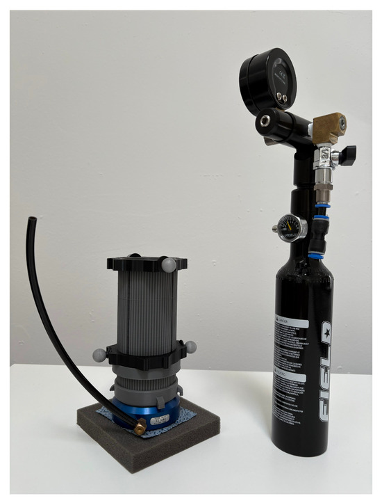
Figure 3.
Air tank container with the air bearing laid on a microfibre cloth, reflective markers (left), and pneumatic system (right).
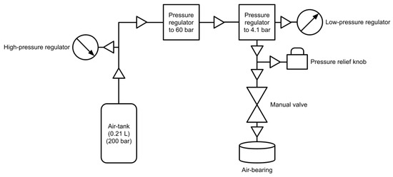
Figure 4.
Detailed schematics of the FSS pneumatic system.
It has a built-in regulator that delivers air at a pressure of 60 bar (800 psi), with a maximum utilisation pressure of about 310 bar (4500 psi). Since the air bearing works at an operating pressure of bar, the pressurized air passes through a low-pressure regulator to monitor it through an external gauge.
The pressure relief knob, or safety valve, is attached to the low-pressure regulator to regulate it to a desired value, along with a manual valve that allows the airflow to be simply shut off or enabled. The air bearing is flat and round, with a diameter of 65 mm. The entire apparatus weighs approximately 1 kg, taking into account both the tank container and the air bearing, whereas the air tank has an approximate operative time equal to 1 h, between recharges, for supporting experiments’ phases. As already described, around the 3D-printed container are fixed four highly reflective markers to let the Motion Capture System track the FSS on the granite monolith. Eventually, the low-pressure regulator, with a 90° air supply unit, guarantees the connection between the self-resetting safety valve and the below-standing flat air bearing through the air hose. The air tank is refilled by an air compressor that harnesses an oil–water separator, a carbon filter rod, and one sponge to reduce moisture in the tank during recharge.
The main novelty lies in the possibility of decoupling the position dynamics control from the FSS by actuating the granite slab via linear actuators, instead of actively exploiting actuation devices like thrusters, obtaining a lighter and more compact apparatus to be accurately tracked by the MCS through reflective markers. The FSS mass reduction would help to reduce the air pressure into the air bearing to grant longer experimental timeframes between two air-tank recharges.
2.3. Motion Capture System
The MCS is an important part of the testing setup, as it enables the tracking of the position of the floating system, which is also used later for closed-loop position control. The system is made up of four infrared (IR) cameras (OptiTrack Flex-13 series) mounted on tripods. The tracking system relies on a set of markers mounted on the rigid bodies of interest. These markers reflect the infrared signal emitted by the cameras, enabling their localization within the tracking volume. These markers (bolded points in Figure 5) are placed on the FSS system (red markers), allowing its position to be continuously monitored, as well as on the matching plane corners (light blue) and on the supporting underlying structure (yellow).
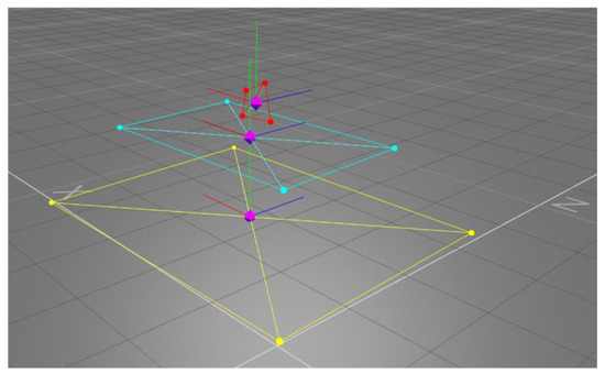
Figure 5.
MCS visualization output, showing the FSS (red), the granite table (cyan), and the stainless steel table (yellow).
Their barycentres are indicated by rhomboid symbols (bolded violet). A corresponding virtual body is defined within the MCS software, starting from the detected markers. The final output of the MCS is the position of the desired rigid bodies’ centre of mass. A numerical algorithm is then implemented to evaluate the FSS speed, starting from the sampled positions. Specifically, a backward numerical derivative is used. Position values are extracted every seconds; hence, the FSS velocity can be extracted as in Equation (1). The system’s characteristics are summarised in Table 2, from [24].
Table 2.
Characteristics of the MCS.
2.4. Tether Testing System
The TTS was studied to carry out tests in both deployed (see Figure 6 and Figure 7) and under-deployment scenarios (see Figure 8). Two different configurations were proposed, accounting for the two scenarios. The facility was designed to emulate one half of a tethered spacecraft. Specifically, the TTS enables the replication of the relative dynamics of one of the satellites with respect to the centre of mass of the tethered system. If the tethered spacecraft consists of two identical satellites connected by a tether, the centre of mass corresponds to the midpoint of the tether. This assumption of symmetry holds if the tether is held in tension at all times.
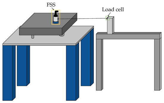
Figure 6.
Illustration of the TTS-deployed (static) architecture.
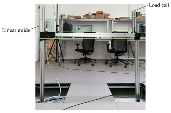
Figure 7.
TTS-deployed (static) architecture.
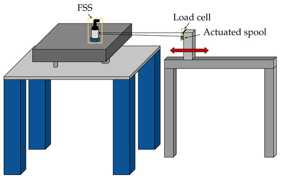
Figure 8.
Illustration of the TTS-deployment (dynamic) architecture.
The concept involves placing the FSS on the FP, while a wire, which simulates the tether, is connected to the FSS and to a point that can be fixed or movable.
In the first case, the anchor point is considered to be on the orbital trajectory, while the FSS is moving with respect to it in accordance with the orbital relative dynamics. This configuration allows for emulating the real-case scenario in which the tether is deployed. The deployed configuration is studied by a setup comprising an aluminium support structure, a linear guide with an actuated prismatic joint, and a load cell (of the LSB-200 series by Futek) for real-time tension measurement. Specifically, two aluminium rods and the linear guide form a U-shaped support structure, where an extra aluminium profile is fixed with the load cell attached to it. The tether is then connected to the FSS and the load cell with two knots. In this case, the guide does not allow relative motion, although it ensures alignment and structural support.
In the second case, the anchor point is always considered to be on the orbital trajectory, while the FSS is moving with respect to it in accordance with the orbital relative dynamics. However, the anchor point can be translated. The idea is to have the possibility of emulating the deployment of the tether. In this case, by moving toward or away from the anchor point with respect to the FSS, and by having an active control on the tether length, the setup allows for emulating a controlled deployment, where the two satellites are separating and the tether is extended and kept in tension. The setup for the deploying case needs an actuated spool to provide tension control during the deployment. The setup for this configuration (Figure 8) is derived from the desire to keep the FSS as lightweight as possible, with the aim of maximizing its usage time between two recharges. As a result, both the actuated spool and the load cell—features shown in Table 3—have been mounted on the vertical support, with the tether being wrapped on the actuated spool. Its free end extends toward the FSS, which houses a passive spool, before being routed back to the vertical support, where it is secured to the load cell. With this setup, it is possible to perform a controlled deployment, where a constant value of tension is achieved by the combined action of the linear guide and the actuated spool. From a dynamic standpoint, the presence of the double cable attached to the FSS should not affect its dynamic response as long as one keeps in mind that the true force acting on the FSS is twice the value measured by the load cell. The deployed scenario is discussed in depth and tested in this paper, while the deployment scenario is provided as a key finding for future integration into the proposed testbed.
Table 3.
Tether subsystem’s properties.
3. Mathematical Models for On-Orbit Dynamics
The testbed was developed to study the relative dynamics of two satellites in a close-proximity configuration, generally defined as the target and chaser.
3.1. In-Orbit Dynamical Model
Under the hypothesis that the target moves on a circular orbit and its relative distance is smaller than the target’s orbital radius, the Hill–Clohessy–Wiltshire (HCW) linearized equations of motion hold true. The HCW equations are written in the Local-Vertical–Local-Horizontal (LVLH) reference frame shown in Figure 9. The framework at hand is a Cartesian Coordinate System (CCS) centred in the target (T)’s centre of mass, where the axis lays on the radial direction from the primary body to the target, the axis lays on the along-track direction, and the axis completes the right-hand triad being perpendicular to the orbital plane, in the same direction of the angular momentum, while R is the primary body radius. The subsequent equations of motion (EoMs) are written in Equation (2),
where represents the components of the position vector of the chaser’s centre of mass (CoM) with respect to the target’s CoM, expressed in the LVLH CCS. Dot notation stands for the derivative with respect to the time .
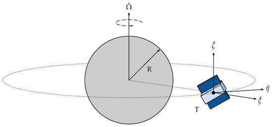
Figure 9.
Local-Vertical–Local-Horizontal Cartesian Coordinate System with origin at the centre of mass of the target (T).
is the orbital angular velocity of the target spacecraft, is the resultant of forces acting on the chaser, and M represents its mass.
3.2. Buckingham Theorem and Scaled Orbital Dynamics
To replicate the relative orbital dynamics on a smaller and more compact testbed, it is necessary to scale the HCW equations [25]. Based on [4,26], the dynamic similarity is ensured between the two systems by applying the Buckingham theorem and the principle of similarity. The Buckingham theorem states that if a phenomenon is described by p variables, with q fundamental units involved, the entire system can be expressed using dimensionless parameters, called variables. By imposing equality between the variables of the real case and those of the scaled case, the principle of similarity ensures dynamic similarity between the two [27,28]. The system involves a total of 15 variables:
A new set of variables is introduced for the scaled system:
It is possible to recognize that there are three fundamental units: length, mass, and time. As a consequence, a total of 12 variables can be identified and used to establish the similarity conditions between the two systems. The final result is shown in the system of equations shown in Equation (3). In detail, the scaling factors for the three fundamental quantities, namely, , , and , are defined as the ratio between the real case and the scaled variables.
The scaling parameters for the derived quantities involved, such as velocity, acceleration, force, and mean motion, are then evaluated as a function of the fundamental ones. According to the Buckingham theorem, all scaling factors can be written as a function of the three factors referring to the fundamental units. In other words, when a test is to be performed, it is sufficient to set only , , and to obtain all of the scaled quantities involved with the phenomenon. By substituting the relations within Equation (3) into Equation (2), the system of Equation (4) is obtained in a testbed-fixed reference frame of coordinates that will be defined in the next paragraph.
where is the sum of the control action and the disturbances.
3.3. Testbed System and Models
The novel idea behind the proposed testbed is that the plane on which the FSS can freely move is actuated, generating accelerations on the FSS by tip-tilting the matching plane. This section explores the connection between the actuators’ displacements and the acceleration induced on the FSS due to the resulting plane inclination. Figure 10 shows a schematic of the granite slab, where and denote the points where the two linear actuators are mounted, indicates the location of the pillar, d is the distance between the two actuators, l is the distance from each actuator to , and p and q correspond to the sides of the slabs. For the purpose of this analysis, two reference frames are introduced. The first is fixed to the granite slab, centred at the system’s rotation pole , with the axis aligned with p, the axis aligned with q, and the axis completing the right-handed triad. The second reference frame is inertial with respect to the laboratory and is initially coincident with the table-fixed frame when the table is in the levelled equilibrium position. It is now essential to determine the relationship between the actuators’ displacements, and the relative attitude of the table-fixed CCS with respect to the inertial frame, which is then related to the acceleration induced on the FSS. This relationship has already been established in [4,26], and only the most relevant results are discussed here. In the following derivations, the small-angle assumption is applied to simplify the kinematic relations. This hypothesis does not lead to a loss of generality, since with a careful choice of the scaling factors it is possible to arbitrarily choose the order of magnitude of the accelerations to be reproduced, thus always guaranteeing the validity of the model.
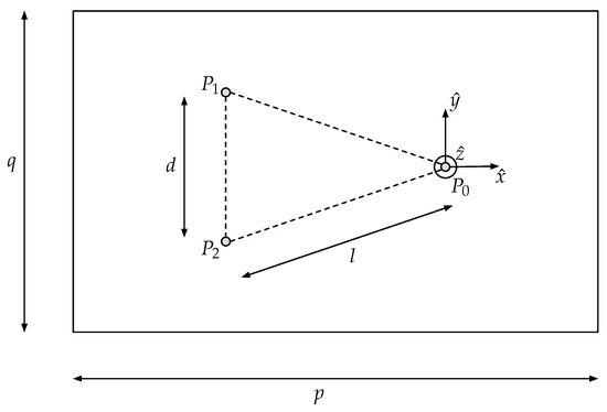
Figure 10.
Granite monolith geometric characteristics.
The positions of points and are respectively
Using a Euler angle and axis parametrization, when a small displacement is applied, a rotation of is made around the vector (see Figure 11).
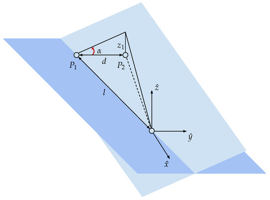
Figure 11.
Schematic view of first linear actuator displacement.
The new attitude of the matching plane is expressed by the Direction Cosine Matrix (DCM) in Equation (6).
When a displacement is applied, a rotation of around is triggered, and the subsequent DCM is obtained with Equation (7) (see Figure 12).
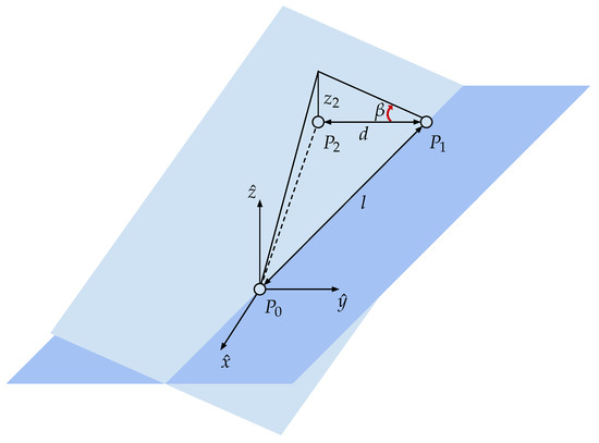
Figure 12.
Schematic view of second linear actuator displacement.
Finally, the attitude of the table after two generic rotations can be expressed as the matrix multiplication of the two DCMs. Assuming that the hypothesis of small displacement holds, the second- or higher-order terms are neglected. The resulting matrix is obtained with Equation (8).
As a consequence, the gravitational acceleration experienced by the FSS in the reference frame of the table is determined by Equation (9).
As shown in Equation (9), the acceleration along is dependent only on the gravitational acceleration, which is balanced by the plane’s normal force, while the other two components are related to the movement of actuators. For this reason, Equation (10) can be written as follows:
By inverting Equation (10), it is possible to write the table’s steering law in Equation (11), which represents the required displacements that are necessary to obtain the desired acceleration components .
Knowing the relations between the displacements of both the actuators and the accelerations experienced by the FSS due to tilting the granite slab, it is possible to obtain a surface map of the reproducible acceleration. As shown in Figure 13, the acceleration a, which is the norm of the vector , can be plotted as a function of and , individuating the accelerations that can be reproduced on the table. In detail, knowing the characteristics of the actuators (summarised in Table 1), and imposing a security coefficient that limits their strokes to 30 mm (±15 mm), the maximum and minimum reproducible accelerations are determined, as reported in Table 4.
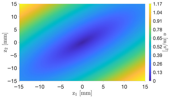
Figure 13.
Map of reproducible acceleration on the monolithic granite table.
Table 4.
Maximum and minimum acceleration reproducible on the matching plane.
The map in Figure 13 refers to an ideal case where the supporting structure on which the actuators are mounted is perfectly flat. However, taking into consideration [19], the testbed may present a slight inclination. This may be partially caused by all of the necessary manufacturing processes that might have plastically deformed the structure at the micrometric level, but it is primarily attributable to the finite resolution of the actuators, which naturally limits the ability of the table to achieve perfect equilibrium. These considerations lead to the possibility of the presence of a residual acceleration that could alter the motion of the FSS, which is consistent with the terminology adopted in related works [29,30,31,32]. For this reason, a worst-case scenario with an expected residual acceleration in the order of magnitude of the minimum reproducible value of m/s2 is considered.
4. Test Campaign
The test campaign is crucial for the testbed. In detail, the campaign is planned not only to conduct a test related to the dynamic control of a tethered system but also to validate the apparatus. In detail, to assess the capabilities and performance of the tip-tilting testbed, a first test is conducted to verify that the system can work in a closed loop, autonomously responding to inputs on the system. A second test is planned to assess the performance of reproducing the orbital dynamics of the Hill–Clohessy–Wiltshire equations.
4.1. Closed-Loop Calibration
The first test involves calibrating the setup by accurately levelling the granite slab to achieve the highest possible horizontal condition. This is allowed through a closed-loop control strategy implemented with a Proportional–Integral–Derivative (PID) controller [33]. By tracking the FSS’s position and velocity with the MCS, the goal is to guide it towards the middle point of the granite surface with zero velocity. As a result, the control action imposed by the table is evaluated by Equation (12):
where and represent the desired final position and velocity, respectively. , , are the gain matrices needed to compute the PID controller.
The acceleration calculated in real time with Equation (12) is then transformed into information on the displacement by computing , as in Equation (11), and fed into the plant. The evolution of the dynamics in terms of position and velocity is then extracted by the Motion Capture System and used as feedback for the control law. The schematic in Figure 14 summarises the process.
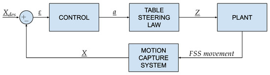
Figure 14.
Flowchart of the closed-loop calibration algorithm.
4.2. Emulation of Linearized Relative Dynamics
The objective of this test is to evaluate how accurately the testbed can replicate the orbital relative dynamics governed by the HCW equations of motion. For this case study, orbital perturbations are neglected, and the motion is analysed solely within the orbital plane. As a consequence, the system in Equation (2) is reduced to 2 degrees of freedom, and the external forces are set to zero, obtaining the set of coupled differential equations in Equation (13) with the initial condition of .
To set up the experiment, it is necessary to relate the LVLH CCS to the table-fixed CCS. Without loss of generality, the and are set to be coincident with and . Moreover, the selection of the scaling factors is fundamental to ensure dynamical similarity. The first scaling factor can be computed according to Equation (3), with the masses of the FSS and the real system. The second scaling factor, , must be selected to ensure that the FSS does not exceed the table’s boundaries; therefore, the constraint in Equation (14) must be respected.
where, after the propagation of the real system trajectories, and can be defined as and , respectively.
The third scaling factor, , has to consider constraints on accelerations. Indeed, as shown in Section 3.3, a residual acceleration of the order of magnitude of 0.0025 m/s2 is considered (see Table 4). To replicate the relative dynamics governed by the HCW equations of motion (EoMs) in the absence of control, it is crucial to ensure that residual accelerations do not significantly alter the FSS dynamics. Therefore, the minimum acceleration has to be at least an order of magnitude greater than the residual acceleration itself (see Table 4), as in Equation (15). Moreover, the scaled accelerations should be lower than the maximum reproducible value in Table 4, as shown in Equation (16), ensuring that the scaled HCW acceleration is dominant over unwanted perturbations.
Equations (15) and (16) define the admissible range of , which is coupled to . In fact, also depends on , since, for longer simulation times, and increase. In addition, must be chosen to ensure a reasonable experiment duration. Therefore, the selection of and is an iterative adjustment process tailored to each experiment, constrained by Equations (14)–(16), while guaranteeing a feasible overall duration.
As the scaling factors are chosen, the system of equations, written in Equation (13), is scaled. Specific sets of scaling parameters are detailed for each experiment in Section 5.2 and Section 5.3.
A new Matlab/Simulink script is developed, and the workflow is shown in Figure 15.
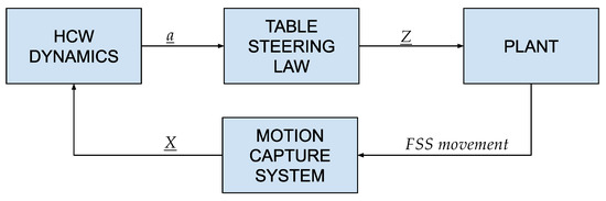
Figure 15.
Flowchart for the HCW emulation test.
Figure 15 summarises the effectiveness of the adopted software to harness the FSS displacements and velocities, tracked by cameras, to compute both linear actuators’ displacements for replicating the desired dynamics on the table through HCW equations of motion, in the absence of control. This feedback control is crucial for testing the discussed control algorithms and proving that the table can efficiently emulate the relative orbital dynamics.
4.3. Fully Deployed Tether Dynamics
The objective of the third experiment is to test the dynamics and control algorithm of a novel cross-track tethered satellite system. Unlike a conventional tethered spacecraft that primarily exploits the gravity gradient torque for radial alignment, the system of interest consists of two satellites connected by a tether that is extended along the cross-track direction ( axis in the LVLH reference frame; Figure 16). In this configuration, the tethered system maintains a perpendicular orientation to the orbital plane. This orientation is particularly suited for remote sensing applications, especially for radar imaging, since multiple radar instruments can be positioned along the tether, obtaining a distributed radar configuration [34]. A key advantage of this architecture is its potential to minimize propellant consumption for formation flying [34]. While similar tethered configurations have been proposed for applications such as position keeping and rendezvous manoeuvres [35], the present configuration introduces a novel tethered system concept, where the tether is maintained in cross-track orientation by generating control forces using thrusters, or aerodynamic drag plates if the spacecraft is flying at Very Low Earth Orbit (VLEO) altitudes [36]. The TSS is composed of two CubeSat platforms, which are connected by a tether with a length that can reach hundreds of meters. If the spacecraft operates in VLEO, each satellite is equipped with two triangular-shaped drag plates designed to interact with the residual atmospheric environment [37], generating control forces that mitigate external disturbances and maintain the tether in a tensioned state, thereby stabilizing the formation. If no residual drag can be exploited, thrusters can be used to stabilize the spacecraft system. The system dynamics is analysed within the LVLH reference frame. The primary objective is to evaluate the testbed’s capability to accurately replicate the orbital dynamics of a TSS in a cross-track configuration.
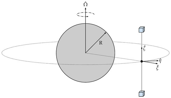
Figure 16.
Illustration of a stabilized TSS in a cross-track configuration.
Specifically, considering the system in circular orbit at an altitude of 500 km, where a tether of 100 m is connected to two CubeSat platforms of 20 kg and is kept in tension by thruster propulsion, and with an initial off-nominal condition where the two satellites are misaligned with respect to the across-track direction, the controller is tasked with correcting the positional error and restoring proper cross-track alignment. Additionally, once the satellites are correctly positioned, the controller is designed to maintain constant tension along the tether.
For the experimental campaign, the TTS-deployed configuration is used (see Figure 6). This setup allows for the simulation of half of the cross-track-tethered satellite, where the dynamics of just one CubeSat is analysed. The CCS is centred on the load cell, at one end of the testbed tether, which corresponds to half of the TSS. The CCS, with respect to the reference frame in Figure 10, is oriented with its , , and axes concordant with the , , and vectors, respectively. As the radial and cross-track directions lie down on the granite plane, the dynamics along is not considered, and the HCW equations of motion are reduced to two degrees of freedom (Equation (17)):
where and are the control actions, while and are the components of the tension along the tether.
Given the order of magnitude of the acceleration involved and the brief time interval in which this phenomenon unfolds, a simplified model, where disturbances are neglected, is assumed.
The along-track motion on is neglected, and the accelerations due to the control ( and ) and the presence of the tether tension ( and ) are considered. During the experiment, a physical tether connected to the FSS introduces the tension, with the architecture described in Section 2.4, while the granite matching plane actuation replicates the joint effect of the HCW and the control. Also, in this case, the system requires scaling, and the same approach described in Section 4.2 is implemented.
In Equation (17), the along-track component is not simply neglected but actively suppressed by postulating an ideal along-track controller. The purpose is to enforce the operational condition of interest, namely, a TSS in the radial/cross-track plane. In HCW notation, this corresponds to adding an along-track control acceleration
which cancels the coupling term in the HCW equations and renders the manifold invariant. Under this closed-loop assumption, the simulated radial and cross-track motions remain consistent with the targeted use case. This simplification therefore does not hinder reproducibility, as it represents the dynamics of a system constrained to maintain along-track alignment. Future work will extend the testbed to include the unconstrained CW model, where radial and along-track dynamics evolve in a fully coupled manner.
A Linear Quadratic Regulator (LQR) controller [33] is designed based on the linearized HCW EoM and a linearized model for the effect of the tether on the dynamics. Specifically, the system is represented by the following system:
where and represent the state and input matrices, respectively, obtained by writing Equation (17) in matrix form:
is the disturbance matrix, related to the effect of the tension on the dynamics, and is the control input. In particular, to design the controller, a linear, elastic model is assumed for the tether, hence giving
where E is the Young’s modulus; S and represent the cross-sectional area and the nominal length of the tether, respectively; and , where and refer to the equilibrium point, is the linear deformation. The optimal LQR controller is in the form , where is built so as to minimize the following cost function:
and are two user-defined weight functions. In order to avoid the possibility of negative tension within the tether, two different matrices are defined, as there are two possible states in which the system can be. When the cable is slack, the spacecraft’s dynamics can be described purely by the HCW EoM, while when there is tension in the tether, the elastic force must also be added. The disturbance matrix varies between the two involved cases, and it is writeable as shown in Equations (23) and (24):
5. Numerical and Experimental Results
In this section, the numerical results of the test campaign are reported and discussed.
5.1. Closed-Loop Calibration
To test the calibration loop described in Section 4.1, the gains are defined after a few iterations of trial and error, as shown in Equation (25):
where is the second-order identity matrix. The desired final state is set to and , where the notation from Section 4.1 is kept. The results are shown in Figure 17.
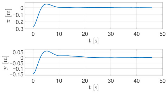
Figure 17.
Time evolution of FSS coordinates over time.
The system reaches the desired state within 0.5 mm after approximately 20 s, with the final actuator chattering in the order of their resolution. This behaviour suggests that it is impossible for the setup to achieve a perfect horizontal attitude, due to the limited resolution of the actuators. As a result, the FSS is expected to experience a residual acceleration of approximately m/s2.
5.2. Emulation of Linearized Relative Dynamics
The evolution of the dynamics of two satellites starting from different radial positions, with zero velocity, is studied using the HCW equations, as explained in Section 4.2. In particular, a starting state of is chosen. The resulting trajectory and acceleration after propagating for 20% of the orbital period are shown in Figure 18 and Figure 19, respectively.
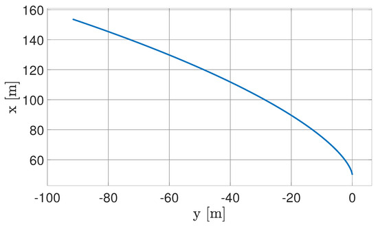
Figure 18.
Real-case trajectory propagated in LVLH CCS.
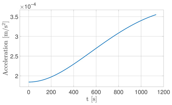
Figure 19.
Real-case acceleration.
The maximum displacement is m, while the acceleration m/s2. Consequently, according to the criteria expressed in Section 4.2, the scaling factors are selected as follows:
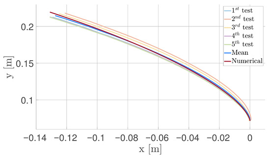
Figure 20.
Comparison between HCW numerically propagated solution and experimental trajectories.
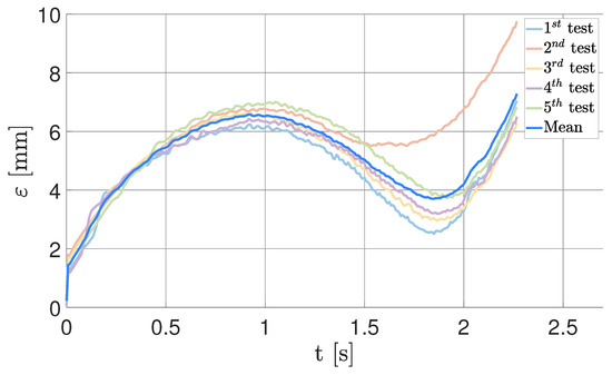
Figure 21.
Absolute error between the numerical and experimental trajectories.
Figure 20 shows that the experimental results match the numerically propagated trajectory with a reasonable error. By increasing the number of tests and considering the mean trend between x and y, spurious effects are mitigated. The main contribution to the discrepancy is the residual acceleration acting on the floater, which is more relevant than the minor ones on the table. Errors related to impurities or small roughness imperfections on the plane were macroscopically identifiable, since they appeared as localized discontinuities in the floater trajectory; these artefacts disappeared once the surface was properly cleaned, confirming their extrinsic nature. Figure 21 highlights the relative error between the numerically propagated trajectory and the experimental results, computed as the norm of the difference between the position vectors at the same instant of time. The results highlight that the table can emulate relative dynamics with a maximum error of mm; this corresponds to 5.5 m when scaled to the real-world case scenario, which is consistent with the hypothesis of a residual acceleration of approximately 2.25 mm/s2.
Lastly, a representative motion profile of the actuators is shown in Figure 22.
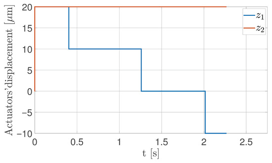
Figure 22.
Displacement profile of the two actuators.
5.3. Fully Deployed Tether Dynamics
The case study for the third test regards a 100 m long tether, starting from an off-nominal slack condition, with the goal of testing the ability of the LQR controller (presented in Section 4.3) to lead the system back to a cross-track configuration and stabilize it. Moreover, the load cell included in the setup is used to measure the value of tension during the whole experiment.
A scaling factor is selected as the ratio of half of the nominal length of the real-case tether and the 1 m cable used in the experiment. As for the , again, a constraint regarding the acceleration range is enforced. Particularly, in this case, only a limit on the maximum acceleration is enforced, since the system is now controlled in a closed loop and, therefore, is able to keep the FSS in the desired position, with a final continuous chattering of the actuators, in a similar way to that described in Section 5.1. Specifically, an acceleration profile, shown in Figure 23, is found with a maximum value of m/s2, which leads to .
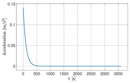
Figure 23.
Real-case acceleration for the uncontrolled cross-track TSS.
According to these constraints, the set of scaling factors is chosen as in Equation (27):
where has simply been evaluated as the ratio of the masses of the real satellite described in the case study (20 kg) and the FSS reported in Section 2.2. As for the tuning of the LQR, two different sets of values for the matrices Q and R are set, based on a trial-and-error campaign. Specifically, for the tensioned case, the selected values are shown in Equations (28) and (29):
The FSS displacements, as shown in Figure 24, stabilize at mm and mm with respect to the origin of the CCS placed on the load cell, observing that the steady-state position is achieved after approximately 20 s of simulation.
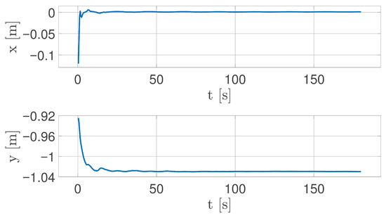
Figure 24.
Time evolution of FSS coordinates under tether tension.
In Figure 25, the measured value of tension stabilizes at approximately 1 mN after approximately 80 s of the experiment. During an initial phase of uncontrolled rotation of the FSS along its vertical axis, the tether stretches more, increasing the tension. The rotation of the FSS around its vertical axes is caused by the pull of the tether itself, which produces a momentum because the tether is not fixed in the centre of mass of the FSS. The presence of the tether helps stabilize the FSS, gradually damping the amplitude of oscillation closer to 0 degrees. However, since no attitude control is implemented, the rotation of the FSS around its vertical axis does not stabilize to a constant value. Therefore, the tension of the tether is close to its steady state around 1 mN but experiences minor oscillations caused by the rotation.
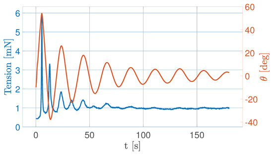
Figure 25.
Tension acting on the FSS (blue) and attitude angle of the FSS (orange).
As a result, the tether contributes to the stability of the system; however, to achieve a more refined attitude, an active control strategy is required.
Also, in this case, for the sake of completeness, Figure 26 and Figure 27 show the motion profiles for the actuators during this third experiment. For comprehension purposes, the graph has been limited to 10 s, since both of the actuators are at rest at 0 μm until the end of the simulation. Moreover, the first 0.25 s is highlighted in Figure 26 to evidence the larger negative displacement of the actuators.
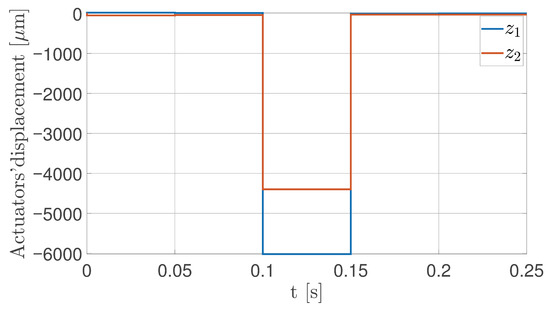
Figure 26.
Actuators’ displacement from 0 to 0.25 s.
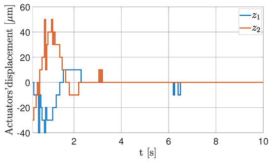
Figure 27.
Actuators’ displacement from 0.25 to 10 s.
6. Conclusions
This paper presents a novel hardware-in-the-loop testbed capable of emulating the relative dynamics between two orbiting spacecrafts, along with an innovative experimental setup for tethered satellite systems.
The design of the testbed is detailed, indicating its subsystems and components, along with the mathematical models, including the derivation of scaling laws based on the Buckingham theorem and the principle of similarity. The equipment and the adopted models allow for an effective and accurate replication of the relative orbital dynamics. Indeed, the experimental results demonstrate the potential of this approach to replicate orbital dynamics within a laboratory environment through a hardware-in-the-loop setup. Specifically, the results show that the FSS follows a trajectory closely matching the one obtained from numerical propagation of the Hill–Clohessy–Wiltshire equation, but low errors are introduced due to the grade of accuracy of the instruments and their microscopic defects. The experiments evaluate not only the capabilities of the testbed to replicate the dynamics described by the HCW equations of motion but also the behaviour of a tethered satellite system in a cross-track configuration.
By considering a real case with accelerations of the order of m/s2 and maximum excursions of m and m in the two main directions, the laboratory testbed reproduced the expected dynamics with a maximum deviation of mm (equivalent to 5.5 m in orbit). The discrepancy was primarily due to a residual acceleration of about mm/s2, while localized disturbances disappeared after proper surface cleaning.
The testbed offers an environmental setup to simulate and test the cross-track tether-assisted stabilization that combines the action of the tether and an LQR controller. Specifically, simulations indicate the ability of the LQR controller to stabilize the tethered spacecraft.
In future work, new components may be integrated into the current architecture to complete the Tether Testing System (TTS), in order to conduct experimental simulations of the deployment phase, which is critical in the design and development of tethered satellite systems.
7. Patents
The main principle underlying the tip-tilt flat-table facility described in this paper is based on two existing patent inventions:
- (1)
- “Method and Apparatus for the Stabilization of a Satellite Formation”, [37].Description: “The invention relates to a method for stabilization of the orbital motion set-up of a group of satellites bound to a tether. To this end, the tension of the tether that connects two or more satellites is controlled in order to keep them in the desired flight formation. This effect is obtained by perturbing a satellite to generate a tension component in the tether, which results in a recoil force that brings the system back into a condition of equilibrium. According to a preferred embodiment, the tension T of the tether is obtained by adjusting the disposition of one or more aerodynamic surfaces provided on the satellites at the ends of the tether”.
- (2)
- “Dynamically tilting flat table to impart a time-varying gravity-induced acceleration on a floating spacecraft simulator”, [38].Description: “Disclosed is a planar test bed comprising a planar surface and further comprising mechanical couplings in mechanical communication with the planar table and the supporting legs. The mechanical couplings are translatable to provide three degrees of freedom for orientation of the planar surface. A processor receives position and velocity information describing an object on the planar surface, and calculates a relative acceleration typically using a function aR = f(t, xR, vR, μt). The processor communicates with the mechanical couplings to establish an orientation where a local gravity vector projects onto the planar surface and generates acceleration with magnitude and direction substantially equal to the desired acceleration aR The operations occur in cyclic fashion so the desired accelerations and planar orientations are updated as an object transits over the planar surface”.
Author Contributions
Conceptualization, A.P., M.C., M.L.V., C.B., G.G., C.L.M., R.A., S.A. and M.R.; methodology, A.P., M.C., M.L.V. and C.B.; software, A.P., M.C., M.L.V. and C.B.; validation, A.P., M.C., M.L.V., G.G. and C.B.; formal analysis, A.P., M.C., M.L.V. and C.B.; investigation, A.P., M.C., M.L.V. and C.B.; writing—original draft preparation, A.P., M.C., M.L.V. and C.B.; writing—review and editing, G.G., C.L.M., R.A., S.A. and M.R.; supervision, G.G. and M.R.; project administration, G.G. and M.R.; funding acquisition, C.L.M., R.A., S.A. and M.R. All authors have read and agreed to the published version of the manuscript.
Funding
This publication is part of the project ASTRO, funded under the Academic PoCs of the NODES Programme, supported by the MUR–M4C2 1.5 of PNRR, funded by the European Union–NextGenerationEU (Grant agreement no.ECS00000036).
Institutional Review Board Statement
Not applicable.
Informed Consent Statement
Not applicable.
Data Availability Statement
The original contributions presented in this study are included in the article; further inquiries can be directed to the corresponding author.
Acknowledgments
The authors would like to thank L. Kalaiselvam, S. Pipolo, P. Vergari, M. De Matteis, M. L. Ottavi, A. V. Atzori, E. Graziano, A. Breda, and A. Milan for their contributions to the design and development of the testbed.
Conflicts of Interest
The authors declare no conflicts of interest.
Abbreviations
The following acronyms are used in this manuscript:
| CCS | Cartesian Coordinate System |
| DCM | Direction Cosine Matrix |
| EoM | Equation of Motion |
| FP | Floating Platform |
| FSS | Floating Spacecraft Simulator |
| GN&C | Guidance, Navigation, and Control |
| HCW | Hill–Clohessy–Wiltshire |
| HIL | Hardware-In-the-Loop |
| MC | Master Console |
| MCS | Motion Capture System |
| LQR | Linear Quadratic Regulator |
| LVLH | Local-Vertical–Local-Horizontal |
| PID | Proportional–Integrative–Derivative |
| TSS | Tethered Satellite System |
| TTS | Tether Testing System |
| VLEO | Very Low Earth Orbit |
References
- Curti, F.; Romano, M.; Bevilacqua, R. Lyapunov-Based Thrusters’ Selection for Spacecraft Control: Analysis and Experimentation. J. Guid. Control. Dyn. 2010, 33, 1143–1160. [Google Scholar] [CrossRef]
- Romano, M.; Friedman, D.A.; Shay, T.J. Laboratory Experimentation of Autonomous Spacecraft Approach and Docking to a Collaborative Target. J. Spacecr. Rocket. 2007, 44, 164–173. [Google Scholar] [CrossRef]
- Wilde, M.; Clark, C.; Romano, M. Historical survey of kinematic and dynamic spacecraft simulators for laboratory experimentation of on-orbit proximity maneuvers. Prog. Aerosp. Sci. 2019, 110, 100552. [Google Scholar] [CrossRef]
- Fernandez, B.R.; Herrera, L.; Hudson, J.; Romano, M. Development of a tip-tilt air-bearing testbed for physically emulating proximity-flight orbital mechanics. Adv. Space Res. 2023, 71, 4332–4339. [Google Scholar] [CrossRef]
- De Stefano, M.; Mishra, H.; Giordano, A.M.; Lampariello, R.; Ott, C. A Relative Dynamics Formulation for Hardware- in-the-Loop Simulation of On-Orbit Robotic Missions. IEEE Robot. Autom. Lett. 2021, 6, 3569–3576. [Google Scholar] [CrossRef]
- Shabana, A.A. Dynamics of Multibody Systems, 1st ed.; Cambridge University Press: New York, NY, USA, 2020. [Google Scholar]
- Rybus, T.; Seweryn, K. Planar air-bearing microgravity simulators: Review of applications, existing solutions and design parameters. Acta Astronaut. 2016, 120, 239–259. [Google Scholar] [CrossRef]
- Pletser, V.; Kumei, Y. Parabolic flights. In Generation and Applications of Extra-Terrestrial Environments on Earth; University Medical Center: Amsterdam, The Netherlands, 2015; pp. 61–73. [Google Scholar]
- Seibert, G.; Battrick, B.T. The History of Sounding Rockets and Their Contribution to European Space Research; ESA Publications Division Noordwijk: Noordwijk, The Netherlands, 2006. [Google Scholar]
- Lappa, M. Space research. In Fluids, Materials and Microgravity; Elsevier: Amsterdam, The Netherlands, 2004; pp. 1–37. [Google Scholar] [CrossRef]
- Zappulla, R.; Virgili-Llop, J.; Zagaris, C.; Park, H.; Romano, M. Dynamic Air-Bearing Hardware-in-the-Loop Testbed to Experimentally Evaluate Autonomous Spacecraft Proximity Maneuvers. J. Spacecr. Rocket. 2017, 54, 825–839. [Google Scholar] [CrossRef]
- Virgili-Llop, J.; Zagaris, C.; Zappulla, R.; Bradstreet, A.; Romano, M. A convex-programming-based guidance algorithm to capture a tumbling object on orbit using a spacecraft equipped with a robotic manipulator. Int. J. Robot. Res. 2019, 38, 40–72. [Google Scholar] [CrossRef]
- Virgili-Llop, J.; Zagaris, C.; Park, H.; Zappulla, R.; Romano, M. Experimental evaluation of model predictive control and inverse dynamics control for spacecraft proximity and docking maneuvers. CEAS Space J. 2018, 10, 37–49. [Google Scholar] [CrossRef]
- Virgili-Llop, J.; Romano, M. Simultaneous Capture and Detumble of a Resident Space Object by a Free-Flying Spacecraft-Manipulator System. Front. Robot. AI 2019, 6, 1–24. [Google Scholar] [CrossRef]
- Boge, T.; Wimmer, T.; Ma, O.; Zebenay, M. EPOS–A Robotics-Based Hardware-in-the-Loop Simulator for Simulating Satellite RvD Operations. In Proceedings of the 10th International Symposium on Artificial Intelligence, Robotics and Automation in Space, Sapporo, Japan, 29 August–1 September 2010. [Google Scholar]
- Eun, Y.; Park, S.Y.; Kim, G.N. Development of a hardware-in-the-loop testbed to demonstrate multiple spacecraft operations in proximity. Acta Astronaut. 2018, 147, 48–58. [Google Scholar] [CrossRef]
- Huang, Z.; Zhang, W.; Chen, T.; Wen, H.; Jin, D. Characterizing an Air-Bearing Testbed for Simulating Spacecraft Dynamics and Control. Aerospace 2022, 9, 246. [Google Scholar] [CrossRef]
- Cho, D.M.; Jung, D.; Tsiotras, P. A 5-dof experimental platform for spacecraft rendezvous and docking. In Proceedings of the AIAA Infotech@ Aerospace Conference, Seattle, WA, USA, 6–9 April 2009; p. 1869. [Google Scholar]
- Yu, B.; Geng, L.; Wen, H.; Chen, T.; Jin, D. Ground-based experiments of tether deployment subject to an analytical control law. Acta Astronaut. 2018, 151, 253–259. [Google Scholar] [CrossRef]
- Yu, B.; Huang, Z.; Geng, L.; Jin, D. Stability and ground experiments of a spinning triangular tethered satellite formation on a low earth orbit. Aerosp. Sci. Technol. 2019, 92, 595–604. [Google Scholar] [CrossRef]
- Mantellato, R.; Lorenzini, E.; Sternberg, D.; Roascio, D.; Saenz-Otero, A.; Zachrau, H. Simulation of a tethered microgravity robot pair and validation on a planar air bearing. Acta Astronaut. 2017, 138, 579–589. [Google Scholar] [CrossRef]
- Bologna, F. Design, Integration and Testing of a Small Floating Spacecraft Simulator. Master’s Thesis, Politecnico di Torino, Turin, Italy, 2023. [Google Scholar]
- Kulke, J. Conceptual Design of an Open-Source Hardware Simplified Floating Spacecraft Simulator. Master’s Thesis, Naval Postgraduate School, Monterey, CA, USA, 2022. [Google Scholar]
- OptiTrack Motion Capture System, Medium Volume Cameras Characteristics. Available online: https://optitrack.com/ (accessed on 18 July 2025).
- Ciarcià, M.; Cristi, R.; Romano, M.M. Emulating Scaled Clohessy–Wiltshire Dynamics on an Air-Bearing Spacecraft Simulation Testbed. J. Guid. Control. Dyn. 2017, 40, 2496–2510. [Google Scholar] [CrossRef]
- Ogundele, A.D.; Fernandez, B.R.; Virgili-Llop, J.; Romano, M. A tip-tilt hardware-in-the-loop air-bearing test bed with physical emulation of the relative orbital dynamics. In Proceedings of the 29th AAS/AIAA Space Flight Mechanics Meeting, Maui, HI, USA, 13–17 January 2019; Volume 168, pp. 3781–3799. [Google Scholar]
- Buckingham, E. On Physically Similar Systems; Illustrations of the Use of Dimensional Equations. Phys. Rev. 1914, 4, 345–376. [Google Scholar] [CrossRef]
- Bridgman, P.W. Dimensional Analysis; Yale University Press: New Haven, CT, USA, 1922. [Google Scholar]
- Gillies, D.C.; Lehoczky, S.L.; Szofran, F.; Watring, D.A.; Alexander, H.A.; Jerman, G.A. Effect of residual accelerations during microgravity directional solidification of mercury cadmium telluride on the USMP-2 mission. J. Cryst. Growth 1997, 174, 101–107. [Google Scholar] [CrossRef]
- Nelson, E. Predicting Residual Acceleration Effects on Space Experiments. Available online: https://gipoc.grc.nasa.gov/pims/MMAP/PIMS_ORIG/MEIT/MEIT_pdfs/meit2004/Section_7.pdf (accessed on 18 July 2025).
- Monti, R.; Paterna, D.; Savino, R. Counter-measures to mitigate residual-g effects on microgravity experiments on the space station. Acta Astronaut. 2002, 50, 209–216. [Google Scholar] [CrossRef]
- Wolf, R.; Rogers, M.; Alexander, J. A residual acceleration data analysis and management system. Adv. Space Res. 1993, 13, 261–265. [Google Scholar] [CrossRef]
- Wie, B. Space Vehicle Dynamics and Control; AIAA: Reston, VA, USA, 1998. [Google Scholar]
- Aliberti, S.; Quadrelli, M.B.; Romano, M. A distributed space radar sounder using a cross-track flying tethered satellite system. Acta Astronaut. 2024, 221, 266–282. [Google Scholar] [CrossRef]
- Bevilacqua, R.; Romano, M. Rendezvous Maneuvers of Multiple Spacecraft Using Differential Drag Under J2 Perturbation. J. Guid. Control. Dyn. 2008, 31, 1595–1607. [Google Scholar] [CrossRef]
- Aliberti, S.; Quadrelli, M.B.; Romano, M. Dynamics and Aerodynamic Control of a Cross-Track Tether Satellite System. ESA GNC-ICATT 2023. Available online: https://www.esa-gnc.eu/paper/?paper_id=23098 (accessed on 18 July 2025).
- Romano, M.; Aliberti, S.; Apa, R.; Matonti, C.L. Method and Apparatus for the Stabilisation of a Satellite Formation. WO2024252252, 12 December 2024. Available online: https://patents.google.com/patent/US5810295A/en (accessed on 18 July 2025).
- Virgili-Llop II, J.; Zappulla, R.; Romano, M. Dynamically Tilting Flat Table to Impart a Time-Varying Gravity-Induced Acceleration on a Floating Spacecraft Simulator. Available online: https://patents.google.com/patent/US10297168B1/en?oq=10297168 (accessed on 18 July 2025).
Disclaimer/Publisher’s Note: The statements, opinions and data contained in all publications are solely those of the individual author(s) and contributor(s) and not of MDPI and/or the editor(s). MDPI and/or the editor(s) disclaim responsibility for any injury to people or property resulting from any ideas, methods, instructions or products referred to in the content. |
© 2025 by the authors. Licensee MDPI, Basel, Switzerland. This article is an open access article distributed under the terms and conditions of the Creative Commons Attribution (CC BY) license (https://creativecommons.org/licenses/by/4.0/).