Abstract
Geodetic coordinate information and attitude information of the observation platform are necessary for multi-UAV position alignment and target tracking. In a complex sea environment, the navigation equipment of a UAV is susceptible to interference. High-precision geodetic coordinate information and attitude information are difficult to obtain. Aiming to solve the above problems, a low-precision geodetic coordinate real-time systematic spatial registration algorithm based on multi-UAV observation and an improved robust fusion tracking algorithm of multi-UAV to sea targets considering attitude error are proposed. The spatial registration algorithm obtains the observation information of the same target based on the mutual observation information. Then, geodetic coordinate systematic error is accurately estimated by establishing the systematic error estimation measurement equation. The improved robust fusion tracking algorithm considers the influence of UAV attitude error in the observation. The simulation experiment and practical experiment show that the algorithm can not only estimate systematic error accurately but also improve tracking accuracy.
1. Introduction
UAVs have the advantages of high mobility, good concealment, high speed, and low economic cost [1,2]. Using them to carry tracking radar and other long-range detection sensors can achieve accurate tracking of over-the-horizon targets, and the demand for their application in the military field is increasing day by day [3]. However, considering the uncertainty of the marine environment, the instability of UAVs, and the error characteristics of the radar itself, there are still many problems in achieving accurate tracking of sea targets.
Existing works have many research papers on autonomous positioning without geodetic coordinate information or with low-precision geodetic coordinate information, which are mainly divided into autonomous positioning methods of single platforms, cooperative positioning methods based on auxiliary beacons, and cooperative positioning methods based on multi-platform mutual observation. The autonomous positioning method [4] is mainly divided into map matching [5,6,7] and projection tracking techniques. The map matching technology uses external sensors of the platform to detect the surrounding environment information and compare it with a built-in map for its own matching and positioning, which has high time and space complexity and puts high requirements on the platform’s own performance, making it difficult to meet the requirements of real-time scenarios. The projection tracking technology relies on real-time calculation of the platform’s own displacement for projection positioning, and the main methods are Inertial Navigation System (INS) [8,9], Visual Odometry (VO) [10,11], and Simultaneous Localization and Mapping (SLAM) [12,13,14], but these methods are unable to overcome the effect of cumulative error, which makes it difficult to maintain high-accuracy positioning over long periods of time. The cooperative positioning method based on auxiliary beacons [15,16] relies on auxiliary beacons with known high-precision coordinates, which will fail in the complex environment once the platform maneuvers or moves away from auxiliary beacons. The cooperative positioning method based on multi-platform mutual observation relies on mutual distance and angle measurements between platforms for cooperative positioning, which will increase computational complexity as the number of platforms increases. Because this method is a relative positioning method, it is difficult to calculate the geodetic coordinates of other platforms if precise geodetic coordinates of one platform cannot be obtained in advance. Most of the above research solves the problem of the platform’s own precise positioning but does not combine their own precise positioning and target detection.
UAV attitude error consists of two parts: systematic error and random error. Systematic error is eliminated by error alignment, and random error is eliminated by a filtering algorithm. Spatial registration is a process of estimating or correcting sensor observation systematic error and attitude systematic error through observing the same or a priori information target. Systematic error estimation is an important part of target tracking, which directly affects the target tracking effect. The existing systematic error estimation methods are mainly divided into two categories: offline estimation and online estimation. Offline estimation is a process of collecting the observed data from sensors over a period of time for batch processing to estimate systematic error. The main methods include real-time quality control (RTQC) [17], least square (LS) [18,19,20], maximum likelihood (ML) [21,22], etc. Offline estimation methods can process more data and have higher estimation accuracy, but these methods are pooled in real time and can only solve the case of constant or slowly changing systematic error. Online estimation estimates systematic error of the sensor at the current moment online through real-time data. The main methods include the joint estimation algorithm [23] and decoupling estimation algorithm [24,25], which requires setting the model of error change in advance and has limited applicability. These methods are subject to external influence, and the estimation accuracy is not high. Ref. [26] proposed a first-order differential data processing algorithm to correct the gyroscope data to improve the attitude estimation accuracy. Ref. [27] developed a new polarized compass attitude change heading error modeling and compensation method by means of gated recurrent unit neural networks. Ref. [28] implemented trajectory tracking based on a quaternionic error theoretic model for the linearization of attitude error. Ref. [29] proposed a fuzzy adaptive error state Kalman filter algorithm for attitude estimation in a GPS-free environment. Ref. [30] addressed the modeling uncertainty in attitude estimation of inertial measurement units by combining an error state Kalman filter and a smooth variable structure filter for attitude estimation based on quaternion theory. Ref. [31] estimated multi-UAV sensor detection systematic error and attitude systematic error in an environment without geodetic coordinate information. Most of the above studies on error estimation only focus on one aspect of either the sensor detection systematic error or the attitude systematic error. Few studies consider the alignment abatement of both errors at the same time.
Based on the above, there are two main difficulties in realizing UAV tracking of maritime targets in a low-precision geodetic coordinate environment. One is the effect of low-precision geodetic coordinates on target tracking, and the other is the effect of UAV attitude error on target tracking. In order to solve the effect of low-precision geodetic coordinates on target tracking, a real-time systematic error alignment algorithm for low-precision geodetic coordinates based on multi-UAV observation is proposed to estimate and reduce the geodetic coordinate systematic error in real time. In order to solve the effect of UAV attitude error on target tracking, an improved robust fusion tracking algorithm for multi-UAV to sea targets considering attitude error is proposed.
The main contributions of this paper are as follows:
- (1)
- The proposition of a low-precision geodetic coordinate real-time system error alignment algorithm based on multi-UAV observation;
- (2)
- The proposition of an improved robust fusion tracking algorithm for multi-UAV to sea targets considering attitude error.
The remainder of the paper is organized as follows. Section 2 describes the problem of spatial registration. Section 3 introduces common coordinate transformations and proposes a systematic error estimation method and target tracking method. In Section 4, a simulation experiment and a practical experiment are conducted to verify the proposed novel method. Finally, conclusions are drawn in Section 5. Explanation of main symbols and description of acronym symbols are shown in Table 1 and Table 2.

Table 1.
Explanation of main symbols.
Table 2.
Description of acronym symbols.
2. Problem Description
UAVs A and B detect the target in the designated sea area and find the sea targets T1 and T2. The simulated posture is shown in Figure 1. The observation information of UAVs A and B on sea targets T1 and T2 is , , , . The attitude information is , , and low-precision geodetic coordinate information is , , respectively.
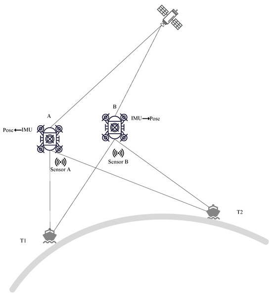
Figure 1.
Posture schematic.
Accordingly,
The observation information of UAV sensors usually consists of three parts: the true value, systematic error of sensor measurement, and random error of sensor measurement. Therefore, the observation information of UAVs A and B on sea targets is related as follows.
The attitude information of the UAV is also composed of the true value, the systematic error, and the random error. Therefore, the attitude information of UAVs A and B is related as follows.
The low-precision geodetic coordinate information of UAV is composed of the true value, the systematic error, and the random error. Therefore, the geodetic coordinate information of UAVs A and B is related as follows.
When the original data are directly used to track the sea target, systematic error cannot be eliminated by filtering. The tracking trajectory of the target will have a certain offset or even divergence. Therefore, systematic errors in geodetic coordinate information, platform observation information, and attitude information need to be estimated and eliminated.
3. Sea Target Tracking Method
3.1. Coordinate Transformation and Conversion Relation
In order to facilitate the elaboration of the subsequent process, the coordinate transformation and transformation relation used afterward are first introduced.
3.1.1. Local Geographic Coordinate System and Earth Coordinate System
The transformation matrix of the local geographic coordinate system to the Earth coordinate system is , and the transformation matrix of the local geographic coordinate system to the Earth coordinate system is . Both are transposed to each other with the expression
where
3.1.2. Unstable Carrier Coordinate System and Stable Carrier Coordinate System
The transformation of the unstable carrier coordinate system to the stable carrier coordinate system is , and the expression is
where
3.1.3. Spherical Coordinate to Cartesian Coordinate
The conversion from spherical coordinate to Cartesian coordinate is , and the expression is
Combining the equations in Section 3.1.2 and Section 3.1.3, the expression for transforming the observation into local geographic coordinates is
3.2. Novel Systematic Error Estimation Method
3.2.1. Acquisition of Observation Information Based on Low-Precision Geodesic Coordinates
Take the example of obtaining the position of UAV B in the local geographic coordinate centered on UAV A.
The observation information of UAVs A and B on the sea target T1 is transformed to the Earth coordinate system, respectively.
Equation (20) minus Equation (19) yields
Therefore, the position of UAV B in the local geographic coordinate centered on UAV A is
3.2.2. Acquisition of Target Position Based on Mutual Observation Information
Position information of the sea target T2 in the local geographic coordinate system centered on UAV A is
Therefore, the position information of the sea target T2 in the local geographic coordinate system centered on UAV B is
Substitute Equation (23) into Equation (24):
3.2.3. Systematic Error Estimation Method
If the geodetic coordinate information, sensor observation information, and attitude information are true, the target position information derived from direct observation information of UAV B on sea target T2 and the target position information derived from mutual observation information are theoretically the same.
First, Equation (26) is expanded by shifting the terms and refinement to obtain
Then, the true value is considered as a function of the measured value and the error value. The low-precision geodesic coordinate information, sensor measurement information, and attitude information are expanded at their measured value in the first-order Taylor expansion. Since systematic error and random error of the measured value are small quantities compared to the true value and the measured value, the higher order can be approximately neglected.
Let
Equation (30) has a first-order Taylor expansion in ,
Let
The specific derivation of Equation (31) is shown in Appendix A.
In summary, we can obtain
Equation (40) can be adopted as a measurement equation for error estimation.
In the sea environment, the sensor deviation and the heading angle error change slowly. Therefore, the state equation of the error estimation is
So far, the real-time estimation of systematic error of the UAV geodesic coordinate information can be completed, and the specific process is shown in Figure 2.
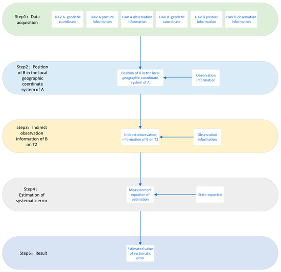
Figure 2.
Flow chart of systematic error estimation.
3.3. Target Tracking Method
Firstly, the corrected geodetic coordinate information is obtained by error reduction based on the estimated geodetic coordinate systematic error , , , of the UAVs.
The original systematic error matrix only consists of the sensor systematic error , but when the UAV detects the target, the attitude angle systematic error has a non-negligible effect on measurement data, so the original systematic error matrix needs dimensional expansion. However, this approach leads to dimensional mismatch. Therefore, the systematic error matrix needs to be dimensionally reduced. The sensor measurement error and attitude angle error are decoupled from the observed data, and a new systematic error matrix is obtained:
where
where is the position of the target in the stable carrier coordinate system .
According to the observation model, the observation equation of the UAV is
Since , is small compared to , it can be approximated by a first-order Taylor linear expansion, which yields
where is the Jacobi matrix of with respect to .
The target observation of UAVs A and B is located in the fusion center
where
is the state of the target in the local geographic reference system of the fusion center.
can be approximated as zero-mean Gaussian white noise.
By subtracting Equation (42) from Equation (43), the expressions for the sensor systematic error and attitude angle systematic error about the UAV measurement can be obtained.
Let
Adding Equation (42) to Equation (43) and eliminating systematic error, we obtain
where is the third-order unit array.
Let
In summary, Equation (49) can be written as
where is approximated as zero-mean Gaussian white noise.
Finally, combined with the Kalman filtering technique, the fast tracking of sea targets can be completed.
4. Experimental Verification
To verify the feasibility of the proposed algorithm, a simulation experiment and a practical experiment were conducted and compared with the methods in references [24,25,32]. Ref. [24] estimated the attitude systematic error and observation systematic error of the missile by simultaneous observation of the target by multiple missiles. Ref. [25] designed a two-stage EKF to accomplish the estimation of the navigation error and observation of the systematic error. Ref. [32] estimates the state of a target without estimating systematic errors based on observations of multiple platforms with multiple identical targets. For the convenience of description, the error estimation method in reference [24] is denoted as EC1, and the error estimation method in reference [25] is denoted as EC2. EC1 and EC2 are combined with the linear filter PLKF and the nonlinear filter EKF to obtain EC1-PLKF, EC1-EKF, EC2-PLKF, and EC2-EKF, respectively. The method in reference [32] is denoted as RT, and the proposed new method is denoted as IRT.
4.1. Simulation Experiment
4.1.1. Parameter Setting
To facilitate the display and comparison of experimental results, the initial position of the offshore target T1 is used as a reference point, and some parameters are set in the local geographic coordinate system centered on the reference point. The data rate is set to , which means every 0.05 s, the platform sensor observes the sea target to obtain observation information, and the inertial guide updates its own attitude information and low-precision geographic coordinate information. The coordinates of UAVs A and B in the local geographic coordinate system of the reference point are , ; the standard deviations of sensor errors (distance, azimuth, azimuth) and attitude angle errors (yaw, pitch, roll) of UAVs A and B are shown in Table 3 and Table 4, respectively.
Table 3.
Error characteristics of UAV A.
Table 4.
Error characteristics of UAV B.
Where and are the geodesic coordinate systematic error scaling factor and attitude angle systematic error scaling factor, respectively, which are used to facilitate the adjustment of error variation in the simulation experiment. The flow of simulation data generation is shown in Figure 3.
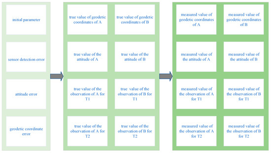
Figure 3.
Simulation data generation.
The motion posture is set as follows: the initial position of the sea target T2 with respect to the reference point is 198,000 m in geodetic length and 0 in geodetic azimuth. Both sea targets T1 and T2 move 2000 m in the direction of geodetic azimuth of 0 in 200 s.
The root mean square error (RMSE) is used for the error evaluation index. The root mean square error of the systematic error of the geodesic coordinate estimation and the position estimation error are calculated as
where can be taken as , , . T is the total duration. , denotes the latitude systematic error and longitude systematic error of the UAV at moment , and is the position estimation error.
In order to visualize the degree of error reduction, the error reduction rate is calculated by Equation (53)
4.1.2. Simulation Experimental Result
In the above scenario taken from , , the simulation is carried out in the set experimental scenario. The estimated effect of the geodesic coordinate systematic error of UAVs A and B is shown in Figure 4 and Figure 5.
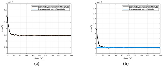
Figure 4.
Error estimation of geodesic coordinate system of UAV A. (a) Effect of longitude systematic error estimation. (b) Effect of latitudinal systematic error estimation.
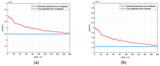
Figure 5.
Error estimation of geodesic coordinate system of UAV B. (a) Effect of longitude systematic error estimation. (b) Effect of latitudinal systematic error estimation.
Figure 3 and Figure 4 show the relationship between estimated value of the geodesic coordinate systematic error and the true value of the geodesic coordinate systematic error of UAVs A and B. It is obvious that the estimated value of systematic error all converges to the true value. Table 5 shows the estimated error of the geodetic coordinate systematic error, which is already a small amount compared to the set true value. The systematic error reduction rate exceeds 70% in different platforms. It shows that the proposed geodetic coordinate systematic error estimation method is effective. The proposed geodetic coordinate systematic error estimation method estimated the systematic error by using EKF in essence. Therefore, the initial value of the system error should be set reasonably.
Table 5.
Systematic error estimation error.
Figure 6 shows the tracking effect using different algorithms in scenario one, and Table 6 shows the position estimation error of different algorithms. Figure 6 shows that it is obvious that IRT has the best tracking result compared to comparing algorithms. The reason for the error in EC1-PLKF and EC1-EKF is that these error estimation methods do not take the effect of attitude angle error and random error in geodesic coordinates into account. EC2-PLKF and EC2-EKF do not take the effect of geodesic coordinate error into account. RT ignores the effect of attitude angle error and geodesic error. In addition, the estimation of the nonlinear filter is slightly better than that of the linear filter.
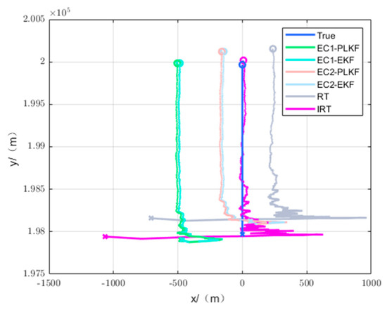
Figure 6.
Tracking effect diagram.
Table 6.
Position estimation error.
Figure 7 shows the tracking position error versus time, from which the conclusion of the tracking performance of various algorithms is approximately the same as above. In addition, it can be obtained that the tracking methods using EC1 and EC2 have a better performance in terms of convergence speed, converging in about 5 s, while RT and IRT have a larger initial error and converge slightly slower than the other algorithms because they use the observed value of the target position as the initial tracking condition, which has a larger error compared to other algorithms that have gone through initial compensation.
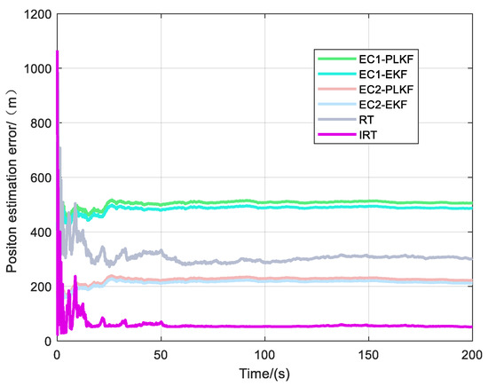
Figure 7.
Tracking position error versus time.
Table 7 shows the average single-step time of different algorithms, where RT has the shortest time because it does not need to estimate any systematic error value but directly estimates the target state. IRT has the longest time because it adds a new proposed geodesic systematic error estimation algorithm compared to RT and considers the influence of attitude angle. Although the time consumption is increased, it remains in the millisecond range and does not affect the performance of the algorithm for practical application.
Table 7.
Average single-step elapsed time.
In order to fully represent the performance of each algorithm under different systematic errors, simulation experiments are performed for , varying from 1 to 100.
Figure 8 shows the variation of the position estimation error of different algorithms as the geodetic coordinate systematic error increases, where varies from 1 to 100 and , focusing on the influence of geodetic coordinate systematic error on the tracking algorithm. Figure 9 and Table 8 reflect the position estimation error data under typical geodetic coordinate systematic error.
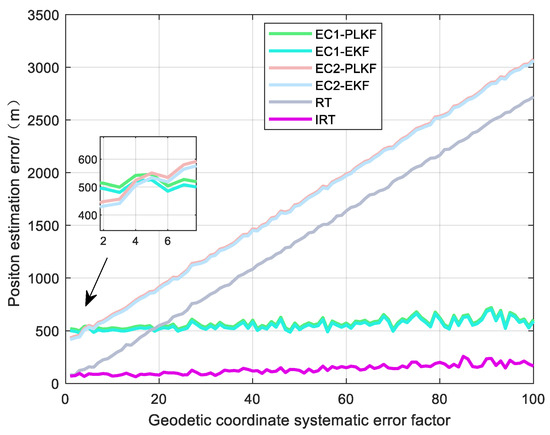
Figure 8.
Position estimation error under different geodetic coordinate systematic errors.
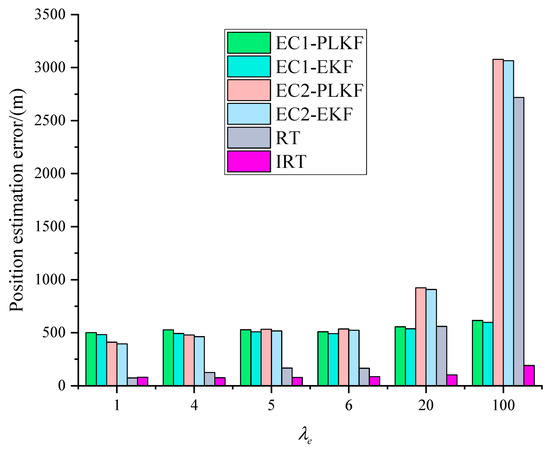
Figure 9.
Position estimation errors under typical geodetic coordinate systematic errors.
Table 8.
Position estimation errors under typical geodetic coordinate systematic errors.
Figure 8 shows that IRT, EC1-PLKF, and EC1-EKF can effectively suppress the effect brought by the error as the geodesic coordinate systematic error increases, while the error of EC2-PLKF, EC2-EKF, and RT keeps increasing. When is larger than 20, the tracking effect of EC2-PLKF, EC2-EKF, and RT starts to be worse than that of IRT because the influence of the geodesic coordinate systematic error on the target position estimation starts to dominate at this time.
When is greater than 5, the tracking effect of EC1-PLKF and EC1-EKF is gradually superior to EC2-PLKF and EC2-EKF. When the geodesic systematic error is small, random error affects the estimation effect of the systematic error of method EC1, which affects the tracking effect. When the systematic error of the geodesic coordinate becomes larger, the effect of random error gradually becomes smaller, and the tracking effect of EC1-PLKF and EC1-EKF is always better than that of EC2-PLKF and EC2-EKF.
When the systematic error increases, the position estimation error of IRT becomes slightly larger because IRT assumes that the geodesic coordinate is true when constructing the coordinate transformation of the observed data by measurement equations. When the geodesic coordinate systematic error keeps increasing, the error from this assumption will keep increasing.
Figure 10 represents the variation of position estimation error for different algorithms as the attitude angle systematic error increases, where varies from 1 to 100 and , focusing on the effect of attitude angle systematic error on the tracking algorithm. Figure 11 and Table 9 reflect the position estimation error under typical attitude angle systematic error.
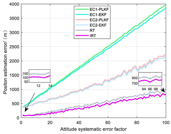
Figure 10.
Position estimation error with different attitude angle systematic errors.
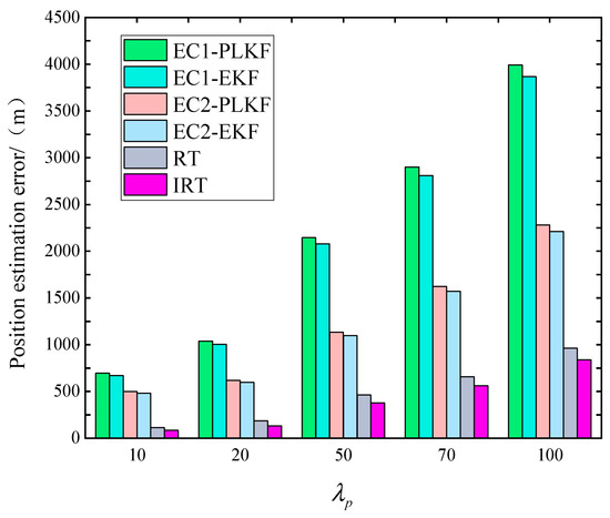
Figure 11.
Position estimation error under typical attitude angle systematic error.
Table 9.
Position estimation error under typical attitude angle systematic error.
The EC1-PLKF and EC1-EKF have the fastest tracking error growth rate because their error estimation algorithms do not estimate the attitude error, and the effect of the increasing attitude error is directly applied to the observation data. The EC2-EKF has a certain suppression effect on the attitude systematic error, but the estimation capability of the algorithm is limited and cannot completely suppress the effect caused by the attitude systematic error. RT and IRT are least affected by the attitude systematic error, and the tracking effect of IRT improves by about 25% compared with RT when the attitude systematic error is 0.1° and about 13% compared with RT when the attitude systematic error is 1°, indicating that the tracking effect of IRT improves with the decreasing attitude error. The reason for this is that when considering the attitude systematic error, it is assumed that the attitude angle is true during the derivation process, and when the attitude angle systematic error is increasing, the error brought by this assumption will increase continuously. IRT The method should be used in the presence of geodetic coordinate system errors that are not excessive.
4.2. Practical Experiment
To further verify the effectiveness of the algorithm, an on-lake experiment was conducted in a certain water.
4.2.1. Introduction to the Practical Experiment
The experimental system consists of an information processor, YAR28(N) radar, Ku02 radar, combined navigation equipment, and RTK. Two small boats equipped with angular reflectors were used as targets in the experiment, and two radars were used to simulate two air platforms for cooperative observation of the targets. Figure 12 shows the experimental procedure. Table 10 shows radar-related parameters.
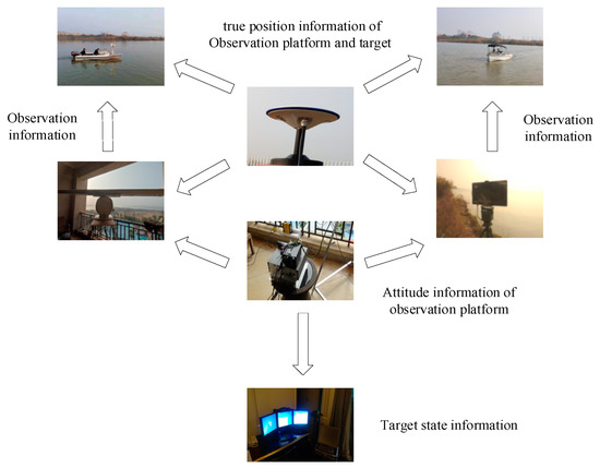
Figure 12.
Experimental procedure.
Table 10.
Radar-related parameters.
4.2.2. Practical Experiment Result
Figure 13 and Figure 14 show the tracking effect of different algorithms under scenarios two and three, and Table 11 shows the position estimation errors of different algorithms under scenarios two and three.
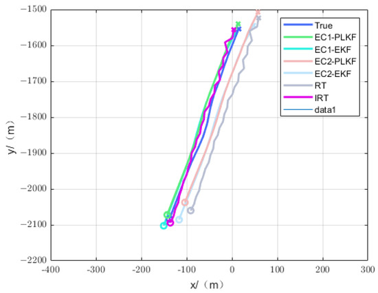
Figure 13.
Tracking effect of scenario two.
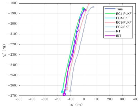
Figure 14.
Tracking effect of scenario three.
Table 11.
Position estimation error for scenarios two and three.
From Figure 13 and Figure 14 and Table 11, it can be seen that under the actual test experiment, only the tracking accuracy of IRT is below 10 m. The tracking performance of IRT is still better than that of EC1-PLKF, EC1-EKF, EC2-PLKF, EC2-EKF, and RT, which is about 1 times better than that of EC1-PLKF and EC1-EKF, 6 times better than that of EC2-PLKF, 2 times better than that of EC2-EKF, and 5 times better than that of RT. The tracking effect of RT decreases, which indicates that the systematic error of the geodesic coordinate has a greater influence on the RT algorithm during the actual measurement experiment, which reflects the necessity of error compensation for the systematic error of the geodesic coordinate.
The novel proposed algorithm is able to perform accurate position estimation of the target with better performance than existing algorithms, which is valuable in engineering applications.
5. Conclusions
The alignment of platform position error is accomplished by multi-UAV observation of sea targets, which can effectively reduce the influence brought by geodesic coordinate error. When tracking the sea target, the influence of platform attitude error is considered, the robust fusion algorithm is improved, and the novel algorithm has better tracking accuracy compared with the traditional robust algorithm and other spatial registration algorithms. The proposed geodetic coordinate systematic error estimation method can reduce systematic error by 70%. IRT has high accuracy when the systematic error is small. The method in this paper has potential applications in realizing accurate target tracking using UAVs in low-accuracy geodetic coordinate environments.
In the future, we will further study the error alignment and target tracking methods in the multi-target case, which may involve the rational allocation of observation resources and heterogeneous data process.
Author Contributions
Conceptualization, J.X. and Q.D.; formal analysis, Q.D. and J.X.; methodology, F.L.; software, Q.D.; validation, Q.D. and F.L.; data curation, Q.D. and J.X.; writing—original draft preparation, Q.D. and J.X.; writing—review and editing, Q.D. and F.L. All authors have read and agreed to the published version of the manuscript.
Funding
This research received no external funding.
Institutional Review Board Statement
Not applicable.
Informed Consent Statement
Not applicable.
Data Availability Statement
Data are contained within the article.
Conflicts of Interest
The authors declare no conflicts of interest.
Appendix A
Equation (A1) is expanded to
Therefore,
where and are the derivatives of and with respect to and , and the expressions are
, and are the derivatives of , , and with respect to , , and , and the expressions are
, , and are the derivatives of with respect to , , and , and the expressions are
References
- Shi, H.-R.; Lu, F.-X.; Wu, L. Cooperative trajectory optimization of UAVs in approaching stage using feedback guidance methods. Def. Technol. 2022, 24, 361–381. [Google Scholar] [CrossRef]
- Zheng, D.; Zhang, Y.-f.; Li, F.; Cheng, P. UAVs cooperative task assignment and trajectory optimization with safety and time constraints. Def. Technol. 2023, 20, 149–161. [Google Scholar] [CrossRef]
- Darvishi, H.; Sebt, M.A.; Ciuonzo, D.; Salvo Rossi, P. Tracking a Low-Angle Isolated Target via an Elevation-Angle Estimation Algorithm Based on Extended Kalman Filter with an Array Antenna. Remote Sens. 2021, 13, 3938. [Google Scholar] [CrossRef]
- Cai, J.; Lei, T. An Autonomous Positioning Method of Tube-to-Tubesheet Welding Robot Based on Coordinate Transformation and Template Matching. IEEE Robot. Autom. Lett. 2021, 6, 787–794. [Google Scholar] [CrossRef]
- Patoliya, J.; Mewada, H.; Hassaballah, M.; Khan, M.A.; Kadry, S. A robust autonomous navigation and mapping system based on GPS and LiDAR data for unconstraint environment. Earth Sci. Inform. 2022, 15, 2703–2715. [Google Scholar] [CrossRef]
- Rohani, M.; Gingras, D.; Gruyer, D. A Novel Approach for Improved Vehicular Positioning Using Cooperative Map Matching and Dynamic Base Station DGPS Concept. IEEE Trans. Intell. Transp. Syst. 2016, 17, 230–239. [Google Scholar] [CrossRef]
- Tian, Q.; Salcic, Z.; Wang, K.I.; Pan, Y. A Hybrid Indoor Localization and Navigation System with Map Matching for Pedestrians Using Smartphones. Sensors 2015, 15, 30759–30783. [Google Scholar] [CrossRef]
- Xiong, H.; Mai, Z.; Tang, J.; He, F. Robust GPS/INS/DVL Navigation and Positioning Method Using Adaptive Federated Strong Tracking Filter Based on Weighted Least Square Principle. IEEE Access 2019, 7, 26168–26178. [Google Scholar] [CrossRef]
- Cheng, J.; Chen, D.; Sun, X.; Wang, T. A simultaneously calibration approach for installation and attitude errors of an INS/GPS/LDS target tracker. Sensors 2015, 15, 3575–3592. [Google Scholar] [CrossRef]
- Kim, D.-H.; Kim, J.-H. Effective Background Model-Based RGB-D Dense Visual Odometry in a Dynamic Environment. IEEE Trans. Robot. 2016, 32, 1565–1573. [Google Scholar] [CrossRef]
- Forster, C.; Zhang, Z.; Gassner, M.; Werlberger, M.; Scaramuzza, D. SVO: Semidirect Visual Odometry for Monocular and Multicamera Systems. IEEE Trans. Robot. 2017, 33, 249–265. [Google Scholar] [CrossRef]
- Trujillo, J.-C.; Munguia, R.; Urzua, S.; Grau, A. Cooperative Visual-SLAM System for UAV-Based Target Tracking in GPS-Denied Environments: A Target-Centric Approach. Electronics 2020, 9, 813. [Google Scholar] [CrossRef]
- Liu, Y.; Miura, J. RDS-SLAM: Real-Time Dynamic SLAM Using Semantic Segmentation Methods. IEEE Access 2021, 9, 23772–23785. [Google Scholar] [CrossRef]
- Lajoie, P.-Y.; Ramtoula, B.; Chang, Y.; Carlone, L.; Beltrame, G. DOOR-SLAM: Distributed, Online, and Outlier Resilient SLAM for Robotic Teams. IEEE Robot. Autom. Lett. 2020, 5, 1656–1663. [Google Scholar] [CrossRef]
- Torres-Gonzalez, A.; Martinez-de Dios, J.R.; Ollero, A. An adaptive scheme for robot localization and mapping with dynamically configurable inter-beacon range measurements. Sensors 2014, 14, 7684–7710. [Google Scholar] [CrossRef]
- Xu, J.; Qian, H.; Dai, H.; Zhu, J. Wireless Sensor Network Localization Based On A Mobile Beacon And Tsvm. Cybern. Inf. Technol. 2014, 14, 98–107. [Google Scholar] [CrossRef]
- Leung, H.; Blanchette, M.; Gault, K. Comparison of registration error correction techniques for air surveillance radar network. Proc. SPIE—Int. Soc. Opt. Eng. 1995, 2, 211–214. [Google Scholar]
- Pan, J.H. Robust Least-Squares Bias Estimation for Radar. In Detecting Biases and Attitude Biases. In Proceedings of the 2013 2nd International Conference on Measurement, Information and Control, Harbin, China, 16–18 August 2013. [Google Scholar]
- Li, D.; Wu, D.; Lou, P. Exact Least Square Registration Algorithm for Multiple Dissimilar Sensors. In Proceedings of the 2017 10th International Symposium on Computational Intelligence and Design (ISCID), Hangzhou, China, 9–10 December 2017; pp. 338–341. [Google Scholar]
- Pfeifer, T.; Lange, S.; Protzel, P. Advancing Mixture Models for Least Squares Optimization. IEEE Robot. Autom. Lett. 2021, 6, 3941–3948. [Google Scholar] [CrossRef]
- Wei, Z.; Wei, S.; Luo, F.; Yang, S.; Wang, J. A Maximum Likelihood Registration Algorithm for Moving Dissimilar Sensors. In Proceedings of the 2019 IEEE 8th Joint International Information Technology and Artificial Intelligence Conference (ITAIC 2019), Chongqing, China, 24–26 May 2019. [Google Scholar]
- Okello, N.; Ristic, B. Maximum likelihood registration for multiple dissimilar sensors. IEEE Trans. Aerosp. Electron. Syst. 2003, 39, 1074–1083. [Google Scholar] [CrossRef]
- Fortunati, S.; Gini, F.; Greco, M.S.; Farina, A.; Giompapa, S. An EM-based approach to the relative sensor registration in multi-target scenarios. In Proceedings of the 2012 IEEE Radar Conference, Atlanta, GA, USA, 7–11 May 2012. [Google Scholar]
- Lu, X.; Xie, Y.; Zhou, J. Improved Spatial Registration and Target Tracking Method for Sensors on Multiple Missiles. Sensors 2018, 18, 1723. [Google Scholar] [CrossRef]
- Wang, C.F.; Wang, H.Y.; Shi, Z.S. Error registration algorithm for maritime multi-platforms based on two-stage extended Kalman filtering. Syst. Eng. Electron. 2011, 33, 851–855. [Google Scholar]
- Wen, X.D.; Liu, C.W.; Huang, Z.P.; Su, S.J.; Guo, X.J.; Zuo, Z.; Qu, H. A First-Order Differential Data Processing Method for Accuracy Improvement of Complementary Filtering in Micro-UAV Attitude Estimation. Sensors 2019, 19, 16. [Google Scholar] [CrossRef] [PubMed]
- Zhao, D.H.; Liu, Y.Z.; Wu, X.D.; Dong, H.; Wang, C.G.; Tang, J.; Shen, C.; Liu, J. Attitude-Induced error modeling and compensation with GRU networks for the polarization compass during UAV orientation. Measurement 2022, 190, 10. [Google Scholar] [CrossRef]
- Ghiglino, P.; Forshaw, J.L.; Lappas, V.J. OQTAL: Optimal Quaternion Tracking Using Attitude Error Linearization. IEEE Trans. Aerosp. Electron. Syst. 2015, 51, 2715–2731. [Google Scholar] [CrossRef]
- Youn, W.; Rhudy, M.B.; Cho, A.; Myung, H. Fuzzy Adaptive Attitude Estimation for a Fixed-Wing UAV With a Virtual SSA Sensor During a GPS Outage. IEEE Sens. J. 2020, 20, 1456–1472. [Google Scholar] [CrossRef]
- Youn, W.; Gadsden, S.A. Combined Quaternion-Based Error State Kalman Filtering and Smooth Variable Structure Filtering for Robust Attitude Estimation. IEEE Access 2019, 7, 148989–149004. [Google Scholar] [CrossRef]
- Dai, Q.; Lu, F. A New Spatial Registration Algorithm of Aerial Moving Platform to Sea Target Tracking. Sensors 2023, 23, 6112. [Google Scholar] [CrossRef]
- Cui, Y.; Xiong, W.; He, Y. Target Robust Tracking Algorithm in Ground-air Collaborative Defense System. ACTA Aeronaut. Astronaut. Sin. 2014, 35, 1079–1090. [Google Scholar]
Disclaimer/Publisher’s Note: The statements, opinions and data contained in all publications are solely those of the individual author(s) and contributor(s) and not of MDPI and/or the editor(s). MDPI and/or the editor(s) disclaim responsibility for any injury to people or property resulting from any ideas, methods, instructions or products referred to in the content. |
© 2024 by the authors. Licensee MDPI, Basel, Switzerland. This article is an open access article distributed under the terms and conditions of the Creative Commons Attribution (CC BY) license (https://creativecommons.org/licenses/by/4.0/).