Abstract
Bionic herringbone riblets are applied to relieve the flow near the blade endwall in a linear compressor cascade under the incidence angle of −4° to 6° at a Reynolds number of 382,000. The herringbone riblets are placed at the endwall upstream of the blade, and the Reynolds-averaged Navier–Stokes simulations are performed to explore their effects on corner separation and the control mechanism. The results show that the herringbone riblets can effectively improve the corner separation over the stable operating range, and the control effect is affected by the riblet height and the yaw angle. The implementation of herringbone riblets with a height of only 0.08 boundary layer thickness and a yaw angle of 30 degrees can reduce the total pressure loss by up to 9.89% and increase the static pressure coefficient by 12.27%. Flow details indicate that small-scale vortices in the riblet channels can accumulate and form a high-intensity large-scale vortex close to the bottom of the boundary layer downstream. Compared with traditional vortex generators, the herringbone riblets induce a vortex closer to the wall due to their smaller size, which can reduce the damage of an induced vortex to the mainstream and enhance its control over the bottom of the boundary layer, thereby effectively reducing additional losses. The induced vortex enhances mixing and injects kinetic energy into the low-energy fluid, thus inhibiting the transverse migration of low-energy fluid in the endwall boundary layer, delaying the formation of the separating vortex, further suppressing the development of corner separation and improving the aerodynamic performance of the cascade.
1. Introduction
By 2025, the aviation industry is expected to contribute 1.5 billion tons of carbon dioxide emissions annually [1]. Hence, modern gas turbine engines are expected to improve efficiency further and reduce weight to reduce carbon dioxide emissions. For this purpose, reducing the compressor stages while maintaining performance is critical, which requires a further increase in blade loading. Nevertheless, the augmentation in blade loading shall exacerbate the axial reverse pressure gradient and the transverse pressure gradient. These effects promote the aggregation of low-energy fluid at the junction between the endwall and the suction surface of the blade, ultimately instigating the onset of corner separation. Corner separation induces the blockage of cascade passages and consequent high flow losses, thereby lowering the stability margin and efficiency of the engine [2]. Consequently, the development of flow control techniques for mitigating corner separation becomes crucial in minimizing flow losses.
For corner separation control, researchers have carried out a lot of research and have developed boundary layer aspiration [3,4], plasma [5,6] or fluidic [7] actuators, continuous and synthetic jets [8], a non-axisymmetric endwall [9,10], vortex generators [11,12,13,14], blade-end slots [15,16] and other active and passive control technologies. As a typical passive control method, the traditional blade-type vortex generator has been successfully applied in the corner separation control due to its effectiveness and easy implementation [11,12]. However, this type of vortex generator also introduces additional losses while controlling corner separation. These losses are mainly caused by the mixing of induced vortices and the windward resistance of the vortex generation geometry. Reducing the size of the vortex generator can move the induced vortex closer to the bottom of the boundary layer and reduce the geometric upwind resistance, thus reducing the additional loss [13,14]. However, the reduction in the size of the vortex generator will lead to a significant reduction in the strength of the induced vortex. According to the research results of Lin et al. [17], traditional vortex generators lose the ability to control flow separation when the geometric height is less than 0.2 boundary layer thickness. Therefore, a new vortex generator structure which can maintain the control effect and further reduce the additional loss is urgently needed.
The development of herringbone riblets is based on the microscopic patterns found on the secondary flight feathers of avian species [18,19,20]. Although the number and structural size of flight feathers are different with each bird species, they in general have the basic form of a central hollow supporting rachis and several slant barbs. The herringbone riblets have evolved from flight feathers and consist of a spanwise arrangement of right-tilted and left-tilted micro-riblets, placed in an alternating manner adjacent to one another [21], as shown in Figure 1. As a passive control technology, herringbone riblets have attracted attention recently because of their excellent performance in drag reduction. Through water tunnel experiments, Chen et al. [19] realized a 16% reduction in drag in a turbulent pipe flow by placing herringbone riblets on the pipe’s inner surface. Benschop and Breugem [22] explored the flow structure induced by herringbone riblets through direct numerical simulation (DNS) and realized a friction drag reduction of 2% by adjusting the geometry of the riblets. Through hot-wire measurements, Nugroho et al. [23] demonstrated that herringbone riblets generated a large-scale secondary flow motion within the boundary layer, resulting in an upwash along the converging line and a downwash along the diverging line. This roll mode has also been observed by Kevin et al. [24] in a turbulent boundary layer and Xu et al. [25] in a laminar boundary layer using the stereoscopic particle image velocimetry technique.
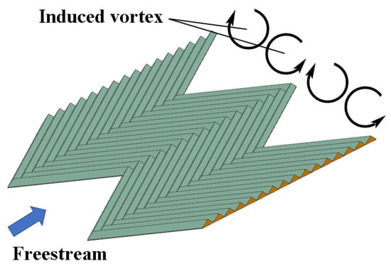
Figure 1.
Schematic diagram of bionic herringbone riblets.
It is anticipated that this induced secondary flow motion will enhance fluid mixing in the boundary layer, thereby offering a valid means to mitigate flow separation. Motivated by this concept, Guo et al. [26] endeavored to manage the laminar separation over a rounded ramp facing backward, utilizing herringbone riblets, while investigating the impact of the yaw angle, height, and spacing of riblets. They found a stronger secondary flow motion resulting in a more significant reduction in the length of the flow separation zone.
In addition, herringbone riblets can also control flow separation when considering the impact of shock waves. The supersonic tunnel experiments carried out by Quan et al. [20] showed that herringbone riblets can effectively improve total pressure recovery by suppressing shock-induced flow separation. The study of Liu et al. [21,27] is one of the first to apply herringbone riblets to the linear cascade. In their study, herringbone riblets were placed on the suction surface of the cascade to control the profile loss of the blade, achieving a substantial reduction of 16.8% in pressure loss.
The above research shows that herringbone riblets can be viewed as an array of micro-scale vortex generators oriented in the flow direction. Even if the herringbone riblets are comparatively smaller in size than the traditional vortex generators, the strength of the induced vortex created by herringbone riblets is guaranteed by the cumulative impact of the micro-scale riblets, and a smaller size means fewer additional losses. Now that traditional vortex generators have been successfully applied in corner separation control [11,12,13,14], the herringbone riblets are considered to have great potential in controlling corner separation. As far as the authors are aware, the effects of herringbone riblets on the corner separation of a cascade have not been reported. This paper aims to introduce bionic herringbone riblets into the control of corner separation and investigate the influencing factors and physical mechanisms of these riblets in controlling corner separation.
This paper’s structure is delineated as follows. First, the studied prototype compressor cascade and the numerical methods are described in Section 2. Then, Section 3 introduces the geometric parameters and placement scheme of the bio-inspired herringbone riblets. Finally, the law and mechanism of the effects of the herringbone riblets on corner separation are presented in Section 4, with Section 5 presenting the primary conclusions of this study.
2. Cascade Geometry and Numerical Method
2.1. Geometric Parameters of Prototype Cascade
The prototype cascade consists of 13 blades. For the blade, its thickness distribution is the NACA 65-009, and its mean camber line is a circular arc with a camber angle of . Figure 2 shows the schematic diagram of the cascade element, where and represent the geometric chord length and axial chord length of the cascade, respectively, represents the pitch of the cascade, and represent the design upstream and downstream flow angle, respectively, represents the camber angle, and represents the incidence angle. Table 1 shows some geometric and aerodynamic design parameters of the prototype cascade. Ma et al. [28,29] conducted a series of experimental studies on the cascade, and the experimental data can be used to verify the effectiveness of the numerical simulation method presented in this paper. In the experiment, two slender sandpaper strips were affixed along the entire span of the cascade’s pressure and suction sides, close to the leading edge, on all of the blades. The purpose of sticking the strips is to eliminate the effect of boundary-layer transition on corner separation by instigating the transition process from laminar to turbulent during the initial phases of boundary-layer evolution on the blade surface. This helps to reduce the burden of Reynolds-averaged Navier–Stokes (RANS) simulations, as no transitional model is required, except the fully turbulent RANS models.
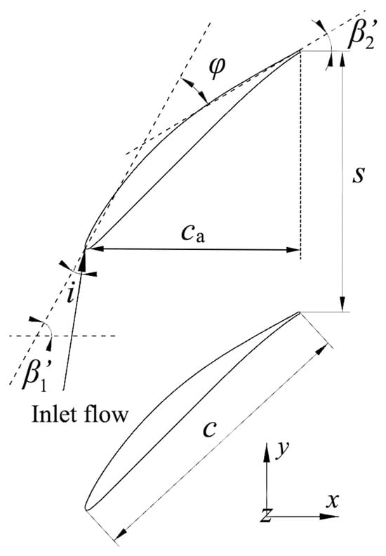
Figure 2.
Sketch of the main parameters of the prototype cascade.

Table 1.
Geometrical parameters of prototype cascade.
2.2. Numerical Method and Experimental Validation
In the present simulations, the Ansys CFX-2021R1 commercial software is utilized to solve the incompressible RANS equations using the stabilized finite volume technique and the high-resolution discretization scheme. DeGroot et al. [30] validated the RANS modeling approach by comparing it with DNS (direct numerical simulations), confirming its accuracy and computational efficiency for studying the turbulent flow in riblet channels. Thus, the RANS modeling approach is used to obtain the aerodynamic performance of the cascade with and without herringbone riblets. To close the system of equations, a two-equation eddy-viscosity model, shear stress transport (SST) , is utilized in conjunction with an automatic wall treatment technique, and this turbulence model has been proven to simulate the flow in the cascade corner accurately [31]. As mentioned above, the transitional model is not applied because the sandpaper strips trigger the transition process. All flow data obtained via numerical simulation in this paper are time-average flow data.
Figure 3 illustrates the computational domain utilized for simulating the linear cascade. To ensure consistency between the simulated and experimental results, the inlet boundary is positioned 3c upstream from the blade’s leading edge. All numerical simulations are carried out at the cascade design Reynolds number of . To precisely establish the velocity profile of the inlet, a prior steady RANS simulation is implemented on a turbulent boundary layer over a flat plate. The freestream velocity profile obtained from the numerical simulation is consistent with the experimental results [29], as depicted in Figure 4. In this study, the boundary layer thickness, , is characterized as the distance from the wall to the point where . According to the velocity profile, the boundary layer thickness of the inlet is . The domain outlet is located 2c downstream of the cascade trailing edge, and averaged static pressure (standard atmospheric pressure) is prescribed at the outlet. To expedite computational time, half of the blade span is modeled with the mid-span boundary set as symmetry, while a single-blade passage is simulated with pitchwise boundaries configured as translational periodicity. In addition, all solid walls are set as adiabatic and no-slip.
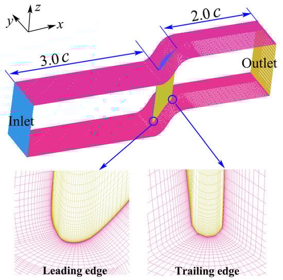
Figure 3.
Computational domain and mesh of prototype cascade.
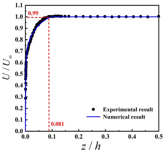
Figure 4.
Mean velocity profile at the inlet.
The commercial software Ansys ICEM-2021R1 is used for mesh generation, and a structured O4H-type grid topology is selected in the passage. To ensure that physically significant features are adequately captured, a thorough sensitivity analysis of the mesh resolution is performed. In Figure 5, the different aerodynamic parameters of the prototype cascade for are shown at three different levels of mesh refinement: coarse (1.4 million), medium (2.0 million) and fine (2.4 million). The aerodynamic parameters obtained from the medium mesh and the fine mesh are consistent. As a result, the medium mesh is chosen to derive all the other results. A close-up view of the mesh near the leading edge and trailing edge of the blade is shown in Figure 3. The distance between the first grid line and the solid wall is set to about m, leading to a corresponding both for the blade and the endwall, and the number of cell layers in the endwall boundary layer region is 42.
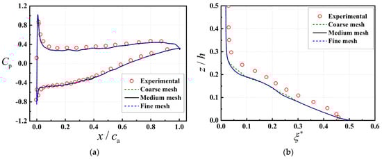
Figure 5.
Comparison of numerical results of the prototype cascade with experimental results, . (a) Static pressure coefficient distribution of prototype cascade at the plane. (b) Spanwise distribution of pitchwise-averaged total pressure loss coefficient at the downstream 0.27c plane.
The reliability of the computational method in this paper can be verified via comparisons with the experimental results [28,29]. Figure 5a displays the static pressure coefficient distribution of the blade wall at mid-span () when , and a satisfactory concordance between the simulations and the experiment results is observed. Figure 5b shows the spanwise distribution of the pitchwise-averaged total pressure loss coefficient at the downstream 27% chord plane when . Based on the quantitative analysis, the computational method is deemed effective in capturing the total pressure loss, albeit with a slight underestimation due to the inherent limitations of the RANS method. In summary, the computational method adopted to obtain the aerodynamic performance of the cascade in this paper is considered reliable.
3. Placement Scheme of Bionic Herringbone Riblets
3.1. Geometric Parameters of Herringbone Riblets
This paper attempts to control the cascade corner separation by arranging herringbone riblets at the endwall upstream of the blade. The herringbone riblets consist of two riblet groups, right-tilted and left-tilted, as shown in Figure 6. The geometric profile of the herringbone riblets is determined by length , width , riblet spacing and yaw angle (the angle between the extension direction of riblet and the centerline of herringbone riblets). The riblets selected in this paper possess unilateral triangular cross-sections, and their geometry is characterized by riblet width and height . The herringbone riblets are situated at the endwall upstream of the blade, and the extension of the centerline of herringbone riblets passes through the stagnation point of the blade’s leading edge. The distance between the trailing edge of the herringbone riblets and the blade’s leading edge is 0.1 , and the stagger angle of the herringbone riblets, that is, the angle between the centerline of the herringbone riblets and the axial direction, is equal to , which means that the freestream is parallel with the centerline of the herringbone riblets when . The placement scheme and geometrical parameters of the herringbone riblets are partly summarized in Figure 6 and Table 2.
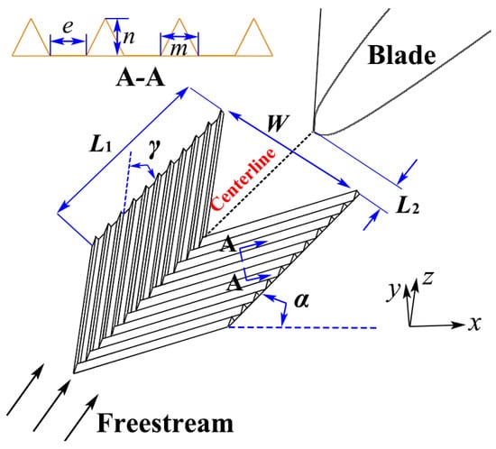
Figure 6.
Placement diagram of the herringbone riblets.
Table 2.
Geometric parameters of herringbone riblets.
According to the research conducted by Guo et al. [26], the key factors influencing the characteristics of herringbone-riblets-induced vorticity are the riblet height and yaw angle . Therefore, riblet height and yaw angle are selected to investigate the influence of herringbone riblets on the aerodynamic performance of the cascade. To achieve this purpose, several schemes are designed for calculation, and eight representative schemes are selected for detailed discussion, as shown in Table 3.
Table 3.
Computational schemes of herringbone riblets.
3.2. Computational Grid and Experimental Validation
To facilitate the generation of the mesh, the herringbone riblets are separated from other computational domains to generate the mesh and are assembled through the interface, whose connection type is general connection. The entirety of the computational domain for the herringbone riblets is discretized by employing a structured mesh that exclusively employs hexahedral cells. A uniform mesh resolution is implemented along the spanwise direction of the riblet passage, whereas a non-uniform mesh discretization strategy that follows a geometric progression with consistent ratios is adopted along the normal direction of the wall. To satisfy the requirement of the turbulence models, the first mesh distance at the solid wall is adjusted to ensure . Furthermore, tests have also been implemented to ensure that the mesh density after installation of the herringbone riblets is sufficient to achieve grid-independent solutions. The different aerodynamic parameters are obtained at three different levels of mesh refinement: coarse (2.7 million), medium (3.2 million) and fine (3.5 million), and the medium mesh is utilized to obtain the aerodynamic characteristics of Case 1 to Case 8 after comparative analysis. A close-up view of the mesh near the herringbone riblets in Case 3 is shown in Figure 7.
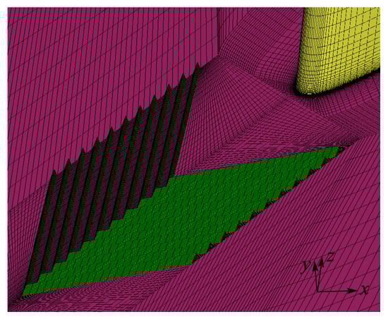
Figure 7.
Close-up view of the herringbone riblets mesh.
As it is a new passive control method, the experimental data on herringbone riblets are very scarce. At present, there is a lack of experimental work on the implementation of herringbone riblets for corner separation control. To verify the reliability of the RANS modeling approach in this paper, an alternative simulation is performed to obtain streamwise velocity profiles of herringbone riblets arranged on a flat plate, as shown in Figure 8a. The PIV data obtained by Xu et al. [25] are used to validate the numerical results. For validation purposes, the same riblet geometry and test condition as in the experiment are adopted. Figure 8b shows the streamwise velocity profiles over the diverging line and converging line at a streamwise location (x = 0.045 m). Comparing the numerical results with the experimental data, it can be seen that the velocity profiles from the numerical simulations are in reasonable concordance with the experimental data, verifying that the RANS modeling approach applied in this paper is adequate to simulate the flow in the herringbone riblets channels.
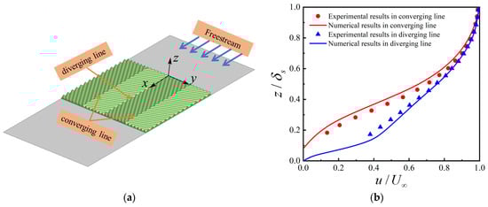
Figure 8.
Comparison of the streamwise velocity profiles obtained through numerical simulation against experimental data [25]. ( is local boundary layer thickness, is freestream velocity). (a) Schematic diagram of herringbone riblets arranged on a flat plate; (b) x = 0.045 m.
4. Results and Discussion
4.1. Data Analysis Method
To quantitatively evaluate the pressure diffusing capacity of the cascade before and after the placement of herringbone riblets, the static pressure coefficient and mass average static pressure coefficient of the cascade are defined here, and their expressions are as follows:
To quantitatively evaluate the total pressure loss of the cascade before and after the placement of herringbone riblets, the total pressure loss coefficient and mass average total pressure loss coefficient of the cascade are also defined here, and their expressions are as follows:
In the formula, and represent the static pressure and total pressure of the incoming flow, and respectively represent the local static pressure and total pressure, and represents the mass flow rate.
When quantitatively evaluating the improvement in the aerodynamic performance of the cascade before and after the placement of herringbone riblets, four parameters are defined: maximum improvement in total pressure loss (), average improvement in total pressure loss (), maximum improvement in the static pressure coefficient (), and average improvement in the static pressure coefficient (). Their expressions are as follows:
In the formula, represents the number of incidence angles involved in the evaluation within the stable working range of the cascade, and the subscripts “bas” and “rib” represent the prototype cascade and the cascade with herringbone riblets, respectively.
4.2. Performance over the Stable Working Range
According to the experimental results of Ma et al. [28,29], the stable working range of the cascade studied in this paper is from to incidence angles. The influence of various design parameters of the herringbone riblets on the aerodynamic performance of the cascade at different incidence angles over the stable working range is discussed in this section. Figure 9 and Figure 10 show the mass-averaged total pressure loss and static pressure coefficients of each herringbone riblets scheme and prototype cascade at the downstream 27% chord plane under varying incidence angles.
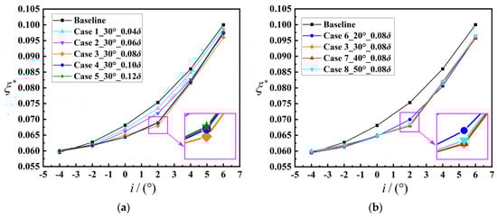
Figure 9.
Total pressure loss coefficient variations with incidence angles (0.27 chord length downstream from the trailing edge). (a) Effect of the riblet height . (b) Effect of the yaw angle .
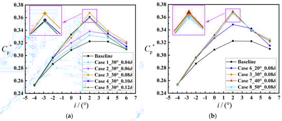
Figure 10.
Static pressure coefficient variations with incidence angles (0.27 chord length downstream from the trailing edge). (a) Effect of the riblet height . (b) Effect of the yaw angle .
Figure 9a shows the effect of riblet height on the mass-averaged total pressure loss coefficient of the cascade at different incidence angles. For the prototype cascade, as the incidence angle increases, the total pressure loss coefficient monotonically increases with a gradually increasing growth rate. Except for the incidence angle, over the stable working range, the total pressure loss coefficients of Case 1 to Case 5 are lower than that of the prototype cascade, and the improvement in total pressure loss initially increases and then decreases with an increase in the incidence angle. The maximum improvement in total pressure loss is obtained near the incidence angle. This finding suggests that the herringbone riblets can effectively enhance the flow in the corner region of the compressor cascade. The aerodynamic performance of the cascade is sensitive to the riblet height . When the riblet height increases from 0.04 to 0.08 , the improvement in total pressure loss is increased in different degrees over the whole stable working range. As the riblet height increases from 0.08 to 0.12 , the improvement in total pressure loss continues to increase in the range of small incidence angles, while the total pressure loss improvement decreases to varying degrees in the range of large incidence angles, indicating the existence of an optimal riblet height.
Figure 9b shows the effect of the yaw angle on the mass-averaged total pressure loss coefficient of the cascade at different incidence angles. Except for the incidence angle, the total pressure loss coefficients of Case 6 to Case 8 are lower than that of the prototype cascade over the stable working range, and the maximum improvement in total pressure loss is obtained near the incidence angle. The aerodynamic performance of the cascade is not very sensitive to the yaw angle of the riblet. Except for the yaw angle, where the improvement in total pressure loss is relatively small, the improvement in total pressure loss is close to the same at , and yaw angles, and the improvement in total pressure loss tends to decrease when the yaw angle is increased to .
The improvement quantity of total pressure loss attained via different schemes is quantitatively compared in Table 4 to further evaluate the control effect of herringbone riblets. The table illustrates that both the average improvement in total pressure loss and the maximum improvement in total pressure loss initially increase and then decrease with an increase in riblet height and yaw angle, respectively. The maximum values of both are obtained in Case 3. Under this design condition, the average improvement in total pressure loss can reach 4.21%, and the maximum improvement can reach 9.89%.
Table 4.
Aerodynamic performance improvement quantity by different schemes. ( represents a decrease in value;
  represents an increase in value).
represents a decrease in value; represents an increase in value).
The effect of different schemes on the mass-averaged static pressure coefficient of the cascade at different incidence angles is shown in Figure 10. For the prototype cascade, the static pressure coefficient initially increases and then decreases with an increase in the incidence angle and reaches the maximum value near the incidence angle. Except for the incidence angle, the static pressure coefficients of Case 1 to Case 8 are higher than that of the prototype cascade in the whole stable working range, and the maximum improvement in the static pressure coefficient is obtained near the incidence angle, which indicates that the herringbone riblets can effectively improve the pressure diffusing capacity of the compressor cascade. The static pressure coefficient of the cascade is also sensitive to the riblet height . With an increase in the riblet height, the improvement in the static pressure coefficient gradually increases, as shown in Figure 10a. However, when the riblet height exceeds 0.08 , the improvement in the static pressure coefficient significantly decreases within the range of large incidence angles, which also indicates that there is an optimal riblet height. The static pressure coefficient of the cascade is not sensitive to the riblet yaw angle , as shown in Figure 10b. The improvement quantity of the static pressure coefficient is the smallest when the yaw angle is , and the improvement in the static pressure coefficient is close to the same at , and yaw angle. When the yaw angle increases to , the improvement in the static pressure coefficient tends to decrease in general, however, the improvement in the static pressure coefficient is increased under the condition of large incidence angles.
The improvement quantity of the static pressure coefficient attained via different schemes is also quantitatively compared in Table 4. The table shows that both the average improvement in the static pressure coefficient and the maximum improvement in static pressure coefficient initially increase and then decrease with the increase in riblet height and yaw angle, respectively. The maximum values of both are obtained in Case 7. Under this design condition, the average improvement in the static pressure coefficient can reach 5.21%, and the maximum improvement can reach 12.53%. In conclusion, the placement of the bionic herringbone riblets at the endwall upstream of the blade can reduce the total pressure loss of the cascade and improve the pressure diffusing capacity of the cascade in a wide range of incidence angles.
4.3. Flow Analysis of Case 3 When
Based on the numerical results above, the control effect of bionic herringbone riblets on the corner separation is influenced by riblet height and yaw angle . To reveal the physical mechanism behind the suppression of corner separation, a detailed analysis is conducted on the flow results of Case 3 when , considering that the maximum average improvement in total pressure loss is obtained in Case 3, and the most significant control effect is observed when in this case.
The spanwise distribution of the pitchwise-averaged total pressure loss coefficient of the prototype cascade and Case 3 at the downstream 27% chord plane when is illustrated in Figure 11a. For the prototype cascade, the total pressure loss coefficient begins to increase significantly when is less than 0.2, and the total pressure loss is greater when the approach to the endwall is closer. Therefore, it is considered that the corner separation region of the prototype cascade at this incidence angle is . After the placement of bionic herringbone riblets, the extent of the corner separation region is reduced, reflected in the fact that the total pressure loss begins to increase significantly only when is less than 0.16. As depicted in the figure, the presence of the herringbone riblets can significantly mitigate the total pressure loss in the corner separation region, and the most significant impact is observed within the range of .
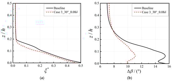
Figure 11.
Spanwise distribution of pitchwise-averaged parameters at the downstream 0.27c plane (). (a) Total pressure loss coefficient. (b) Deviation angle.
The pitchwise-averaged deviation angle () of cascades with and without herringbone riblets along the blade height at the downstream 27% chord plane when is illustrated in Figure 11b. For the prototype cascade, a significant increase in the deviation angle near the trailing edge occurs when is less than 0.2, which indicates a deterioration in the flow and a more pronounced flow separation near the endwall. After placing the herringbone riblets on the endwall, the deviation angles near the endwall are significantly reduced, which shows a noticeable improvement in the flow in the corner region and a reduction in flow separation. In addition, the change in flow in the corner region also affects the flow field near the middle-span blade, as shown by the fact that the deviation angles of the cascade with herringbone riblets increase compared to the prototype cascade when is greater than 0.3. The above results in a tendency for the distribution of the deviation angle of the cascade with herringbone riblets to be uniform along the blade height.
To further obtain the flow details in the corner region of cascades with and without herringbone riblets, the total pressure loss contour and streamlines of the mean flow field of the prototype cascade and Case 3 at different span height sections when are presented in Figure 12. As shown in Figure 12a, the prototype cascade exhibits a large high-loss region (as shown in red) near the blade suction surface at the 5% span height section. The high-loss region extends to approximately 50% of the axial chord for the blade with rolling-up structures in the high-loss regions, demonstrating the presence of large-scale separation. This large-scale separation is also identified via the streamlines of the mean flow field at this section. The placement of the herringbone riblets apparently reduces the high-loss region, and the whole high-loss region is pushed downstream, as shown in Figure 12b. The ideal wall-attached flow near the blade suction surface for the cascade with herringbone riblets is illustrated via the streamlines near the wall, which indicates the suction surface no longer experiences a large-scale separation flow. Compared to the 5% span height section, the high-loss region of the prototype cascade is significantly reduced at the 10% span height section, and only the small-scale rolling-up structure is observed in the high-loss region, as shown in Figure 12a. For the cascade with herringbone riblets, the high-loss region at the 10% span height section is nearly diminished, and the splendid wall-attached flow near the blade suction surface is also depicted by the streamlines, as shown in Figure 12b. At the 15% span height section, the large-scale separation flow is not observed near the blade suction surface for the cascade with and without herringbone riblets, and the employment of herringbone riblets can still reduce the flow loss near the suction surface reflected in the total pressure loss contour. This confirms the abovementioned concept that the bionic herringbone riblets can effectively suppress the cascade corner separation.
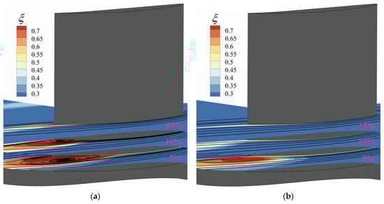
Figure 12.
Total pressure loss contour and streamlines of the mean flow field at different span height sections (). (a) Prototype cascade; (b) Case 3.
Considering that the total pressure loss contours can be utilized to show the location of high-entropy low-momentum fluid, the total pressure loss contours of the prototype cascade and Case 3 at the downstream 27% chord plane when are compared in Figure 13. The diagram shows that the intricate vortical flow present in the corner separation region leads to the highest total pressure loss. For the prototype cascade, the high-loss region is depicted in the range of , as shown in Figure 13a. After placing the herringbone riblets on the endwall, the high-loss region contour is reduced to below the 10% span height, and the high-loss core moves toward the blade suction side, as shown in Figure 13b. The most significant improvement in flow loss is observed within the range of , which is consistent with the results in Figure 11a.
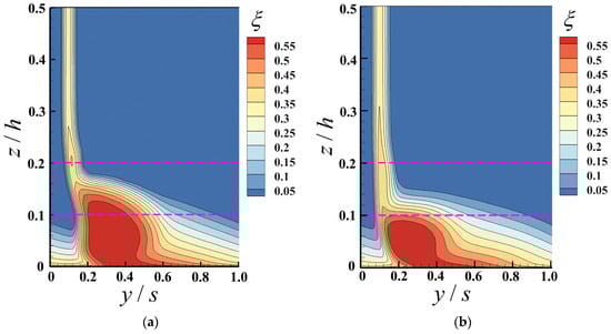
Figure 13.
Total pressure loss contour at the downstream 27% chord plane (). (a) Prototype cascade; (b) Case 3.
As shown in Figure 11, Figure 12 and Figure 13, the corner separation and the corresponding blockage are effectually suppressed by bionic herringbone riblets. To reveal the physical mechanism of the herringbone riblets controlling the corner separation of the cascade, the flow field and vorticity field in the herringbone riblets and cascade channel are further analyzed in the following sections.
4.4. Control Mechanism Analysis
To reveal the physical mechanism of the herringbone riblets controlling the corner separation of the cascade, the flow field and vortex field near the herringbone riblets in Case 3 under the condition are investigated. Figure 14 shows the three-dimensional streamlines in the herringbone riblet channels, upstream and downstream of the herringbone riblets, and the axial vorticity (X-vorticity) fields at the 5% section of the cascade channel and the section of riblet channels. The streamlines flowing through the herringbone riblets induce a large-scale axial-induced vortex near the suction surface of the downstream blade. The size of the induced vortex is approximately 0.5 percent of the cross-sectional area between the two blades. This induced vortex is close to the bottom of the boundary layer, and its vortex direction is opposite to that of the boundary layer. As shown in Figure 14, the herringbone riblets can be viewed as multiple ribbed micro-vortex generators arranged in parallel along a certain direction. When the fluid flows from the centerline into each riblet channel, small-scale spiral flows are formed in the riblet channels due to the pressure difference. Secondary flow motions revealed by the X-vorticity contour in the plane perpendicular to the riblet channels also confirm the existence of the small-scale induced vortices near the tip of the riblet channels, as shown in Figure 14. The small-scale induced vortices move along the riblet channels and eventually leave from the boundary line. These small-scale induced vortices leaving the riblet channels interact with the fluid outside the channels to form the upwash flow and eventually develop together into a large-scale induced vortex along the freestream direction via the accumulation effect. The large-scale induced vortex is likely to augment the process of mixing and facilitate the injection of kinetic energy into the low-energy fluid present in the boundary layer. This enables the boundary layer to withstand the reverse pressure gradient in the axial direction as well as the transverse pressure gradient.
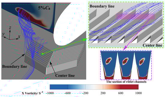
Figure 14.
Three-dimensional flow and vorticity fields around the herringbone riblets (Case 3, ).
The results of Lin et al. [17] show that traditional vortex generators lose the ability to control flow separation when the geometric height is less than 0.2 . However, the bionic herringbone riblets can effectively control the corner separation when the riblet height is only 0.08 . This is because the induced vortex ensures sufficient strength through the accumulation effect of the multiple micro-scale riblets. Furthermore, the smaller size of the herringbone riblets compared to traditional vortex generators allows the induced vortex to be closer to the wall. This proximity reduces the damage of the induced vortex to the mainstream and enhances its control over the bottom of the boundary layer, thus effectively reducing the additional losses.
Considering that the corner separation is not only related to the boundary layer of the endwall and suction surface but also affected by the secondary flow in the cascade channel, the vortex structures of the prototype cascade and Case 3 when are discussed in this section. Figure 15a,c show the X-vorticity contours at various cross-sections (0%, 10%, 20%, 30%, 40%, 60%, 80% and 100% ), illustrating the changes in the primary vortex structures. The corresponding total pressure loss is also compared and presented in Figure 15b,d. The vortex structures in the prototype cascade predominantly comprise the separating vortex (SV) and the corner vortex (CV) in the corner region. It is worth noting that the evolution of the vortex structures is intricately linked to the corresponding total pressure loss. The green three-dimensional isosurfaces are the region of , which represents the backflow regions.
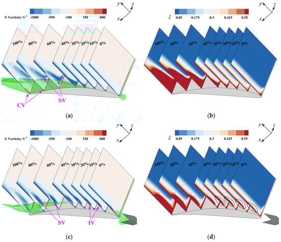
Figure 15.
The X-vorticity and corresponding flow loss of prototype cascade and Case 3 when . (a) X-vorticity of prototype cascade. (b) Total pressure loss coefficient of prototype cascade. (c) X-vorticity of Case 3. (d) Total pressure loss coefficient of Case 3.
For the prototype cascade, when subjected to a powerful transverse pressure gradient, the low-energy fluid that exists in the boundary layer of the endwall tends to accumulate at the intersection between the suction surface of the blade and the endwall. The low-energy fluid begins to take shape at the 30% section and eventually leads to a large-scale backflow in the corner region under the influence of the reverse pressure gradient. The low-energy fluid in the boundary layer rolls up and forms a separation vortex under the action of the backflow region. The separation vortex gradually develops along the span direction as it moves downstream, and the corner vortex is also observed at the blade’s trailing edge, as depicted in Figure 15a. Correspondingly, under the influence of the separation vortex, the extent of the high-loss region of the cascade channel increases rapidly along the axial direction from the 30% section, as shown in Figure 15b.
As the herringbone riblets are introduced in the cascade, the induced vortex (IV) is observed in the boundary layer of the endwall. The induced vortex enhances the mixing between the boundary layer and the mainstream, effectively inhibits the accumulation of low-energy fluid in the corner region, and thus dramatically reduces the extent of the backflow region, as illustrated in Figure 15c. Furthermore, the induced vortex delays the formation of the separation vortex, reduces its size, and inhibits its spanwise development. Additionally, no significant corner vortex is observed in the corner region of the blade’s trailing edge. Benefiting from this, in the range of 30% to 100% , the extent of the high-loss region in Case 3 is significantly reduced compared to the prototype cascade, as shown in Figure 15d. It is worth noting that in the range of 0% to 30% , the total pressure loss of the boundary layer at the endwall in Case 3 is higher than that of the boundary layer at the same position of the prototype cascade due to the mixing effect of the induced vortex. However, due to the small geometric height of the herringbone riblets, the induced vortex is close to the bottom of the boundary layer. As a result, the additional total pressure loss caused by the induced vortex is considered acceptable.
To visualize the affecting mechanism of the herringbone riblets on corner separation, the limiting streamlines at the endwall and suction surface of the prototype cascade and Case 3 when are depicted in Figure 16. For the prototype cascade, due to the influence of the transverse pressure gradient, the suction side branch of the horseshoe vortex is re-absorbed to the blade’s suction surface, thus forming the saddle point (N) at 30% , as shown in Figure 16a. The fluid passing through the saddle point is rolled up transversely and spanwise due to the blockage, and the low-energy fluid formed by mixing the rolled-up fluid with the boundary layer is separated at the endwall and the suction surface under the action of the reverse pressure gradient. The saddle point N is considered the initial point of corner separation and the extent of the three-dimensional corner separation region is delimited by the separation lines and . The low-energy fluid within the boundary layer of the endwall converges to the spiral focus and leaves the endwall. The separation vortex leaving the endwall is again connected to the spiral focus on the suction surface to form a vortex ring, resulting in significant blockage in the corner region.
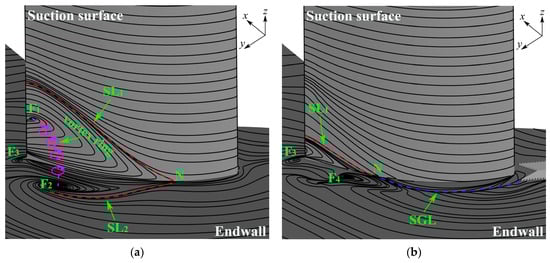
Figure 16.
Limiting streamlines at the endwall and suction surface of the blade (). (a) Prototype cascade; (b) Case 3.
After arranging the bionic herringbone riblets, the fluid within the boundary layer of the endwall forms a streamline gathering line (SGL) as it moves downstream under the influence of the strong vortex induced by the herringbone riblets, as shown in Figure 16b. The low-energy fluid regains energy through mixing and is forced to move downstream along the streamline gathering line, which causes a significant inclination in the transverse migration of the streamlines upstream of the 70% axial chord of the blade. The separation line starts to form from at 70% , while the separation line disappears. The saddle point N moves downstream noticeably, and the extent of corner separation is significantly reduced, resulting in improved flow in the corner region. The spiral focus at the endwall and the spiral focus on the suction surface both disappear, and instead, the spiral focus with an opposite rotation direction to is created by the strong induced vortex. As a result, the vortex ring near the trailing edge of the cascade disappears, and the blockage in the channel is improved.
The flow field and vorticity field show that the herringbone riblets can generate a low-additional-loss-induced vortex via the accumulation effect of the multiple micro-scale riblets. This induced vortex can enhance the mixing between the boundary layer and the mainstream, suppressing the transverse migration of low-energy fluid within the boundary layer, thereby controlling the corner separation. The results in Figure 9 and Figure 10 prove that the control effect of the herringbone riblets is affected by its geometric parameters and the incidence angle. Therefore, to further demonstrate the physical mechanism of different geometric parameters and incoming flow conditions affecting the control of corner separation, Figure 17 shows the X-vorticity fields of herringbone riblets with different geometry and incidence angles at the 30% plane.
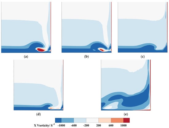
Figure 17.
Vorticity fields of herringbone riblets with different designs at the 30% plane. (a) Case 3, ; (b) Case 6, ; (c) Case 1, ; (d) Case 3, ; (e) Case 3, .
Figure 17a–c are compared to reveal the physical mechanism of different geometric parameters affecting the control of corner separation. When the incidence angle is maintained at , the greatest improvement in total pressure loss is obtained in Case 3, while the improvement in Case 6 and Case 1 is relatively small among all schemes. For Case 3, a strong vortex close to the endwall is observed at the 30% plane downstream of the cascade leading edge, as shown in Figure 17a. Therefore, the low-energy fluid in the corner region of the cascade is effectively controlled. When the yaw angle is reduced (Case 6) based on Case 3, the pressure difference between the two sides of each riblet will decrease due to the decrease in the velocity component in the vertical direction of the riblet, which further leads to a decrease in the strength of the induced vortex at the same plane, as shown in Figure 17b, and the corresponding improvement in corner separation decreases. When the riblet height is reduced (Case 1) based on Case 3, the pressure difference between the two sides of each riblet will also decrease due to the decrease in the absolute velocity, which further leads to a substantial reduction in the strength of the induced vortex at the same plane, as shown in Figure 17c, and the corresponding improvement in corner separation is also minimal. Therefore, the changes in riblet height and yaw angle essentially affect the control of corner separation by influencing the strength of the induced vortex downstream.
Figure 17a,d,e are compared to reveal the physical mechanism of different incidence angles affecting the control of corner separation. When the incident angle decreases from to , the axial reverse pressure gradient of the prototype cascade channel decreases significantly, and the corner separation almost disappears. In this condition, the artificially imposed induced vortex negatively affects the flow field, leading to unsatisfactory control effects of most passive control methods under negative incident angle conditions. The size of the herringbone riblets is smaller than that of traditional vortex generators, which allows the induced vortex to be closer to the wall, thus reducing additional losses. In addition, the change in the angle between the incoming flow and the riblet reduces the strength of the induced vortex, as shown in Figure 17d, which makes the negative gain caused by the induced vortex acceptable. When the incidence angle increases from to , the corner separation region increases significantly. The induced vortex generated by the herringbone riblets moves away from the suction surface, and its strength decreases due to the reduction in the angle between the incoming flow and the riblets, as shown in Figure 17e. Although this weakens the control effect of the herringbone riblets, a certain gain effect can still be obtained.
5. Conclusions
This paper conducts a detailed analysis of the impacts of bio-inspired herringbone riblets on corner separation in a linear cascade through numerical simulation. Additionally, the underlying control mechanism of the herringbone riblets is explored by analyzing the flow within the cascade channel. The primary results of this study are succinctly summarized as follows:
- (1)
- Except for the incidence angle, the bio-inspired herringbone riblets can effectively improve the flow in the corner region within the entire stable working range of the cascade. The riblet height and yaw angle are the two main parameters that affect the control effect of corner separation. Both the total pressure loss improvement and the static pressure coefficient improvement exhibit an initial increase followed by a decrease as the riblet height or yaw angle increases. Optimal results can be achieved when the riblet height is 0.08 and the yaw angle is . The maximum total pressure loss improvement can reach 9.89%, and the maximum static pressure coefficient improvement can reach 12.27% under this design condition.
- (2)
- The herringbone riblets can be viewed as multiple ribbed micro-vortex generators arranged in parallel along a certain direction. Due to the pressure difference between the two sides of each riblet, multiple small-scale induced vortices are formed in the channel of each riblet. These small-scale induced vortices leaving the riblet channels interact with the fluid outside the channels to form the upwash flow and eventually develop together into a large-scale induced vortex along the freestream direction via the accumulation effect. Since the size of the herringbone riblets is smaller than that of a traditional vortex generator, its induced vortex can be placed closer to the bottom of the boundary layer, which can reduce the damage of the induced vortex to the mainstream and enhance its control over the bottom of the boundary layer, thereby effectively reducing additional losses.
- (3)
- The induced vortex of the herringbone riblets enhances the mixing between the boundary layer and the mainstream, effectively inhibits the accumulation of low-energy fluid in the corner region, and makes the separation point move downstream, thus delaying the formation of the separation vortex, eliminating the vortex ring in the corner region, further suppressing the development of corner separation. The geometric parameters and incidence angle of the herringbone riblets further affect the control effect of corner separation by affecting the strength and position of the induced vortex.
As a novel passive control method, the effectiveness and mechanism of herringbone riblets to control corner separation are studied using numerical simulation in this paper. More in-depth and detailed experiments are needed in future work to further verify the effectiveness of herringbone riblets in controlling corner separation, and the other placement scheme of herringbone riblets also needs to be explored in future work.
Author Contributions
Conceptualization and writing—original draft preparation, P.Z. methodology, validation and writing—review and editing, R.C.; formal analysis, investigation and writing—review and editing, Y.L. All authors have read and agreed to the published version of the manuscript.
Funding
This research was supported by the National Natural Science Foundation of China (Youth Program No. 52306058), Natural Science Foundation of Tianjin Municipal Science and Technology Commission (Youth Program No. 22JCQNJC00050) and the Open Fund of Key Laboratory of Civil Aircraft Airworthiness Technology (No. SH2021111908).
Data Availability Statement
Data are contained within the article.
Conflicts of Interest
The authors declare no conflicts of interest.
Nomenclature
| camber angle | |
| pitch spacing | |
| blade span | |
| Reynolds number | |
| incidence angle | |
| total pressure loss coefficient | |
| mass-averaged total pressure loss coefficient | |
| maximum total pressure loss improvement | |
| average total pressure loss improvement | |
| static pressure coefficient | |
| mass-averaged static pressure coefficient | |
| maximum static pressure coefficient improvement | |
| average static pressure coefficient improvement | |
| chord length | |
| axial chord length | |
| local total pressure | |
| local static pressure | |
| static pressure of the incoming flow | |
| total pressure of the incoming flow | |
| mass flow rate | |
| velocity | |
| inflow velocity | |
| boundary layer thickness | |
| length of herringbone riblets | |
| distance between herringbone riblets trailing edge and blade leading edge | |
| wavelength | |
| yaw angle | |
| stagger angle | |
| riblet spacing | |
| riblet width | |
| riblet height | |
| the number of incidence angles involved in the evaluation | |
| deviation angle | |
| design upstream flow angle | |
| design downstream flow angle | |
| axial direction | |
| pitchwise direction | |
| spanwise direction |
References
- Slotnick, J.P.; Khodadoust, A.; Alonso, J.J.; Darmofal, D.L.; Gropp, W.D.; Lurie, E.A.; Mavriplis, D.J.; Venkatakrishnan, V. Enabling the environmentally clean air transportation of the future: A vision of computational fluid dynamics in 2030. Philos. Trans. R. Soc. A Math. Phys. Eng. Sci. 2014, 372, 20130317. [Google Scholar] [CrossRef]
- Yan, H.; Liu, Y.; Li, Q.; Lu, L. Turbulence characteristics in corner separation in a highly loaded linear compressor cascade. Aerosp. Sci. Technol. 2018, 75, 139–154. [Google Scholar] [CrossRef]
- Cao, Z.; Liu, B.; Zhang, T.; Yang, X.; Chen, P. Influence of coupled boundary layer suction and bowed blade on flow field and performance of a diffusion cascade. Chin. J. Aeronaut. 2017, 30, 249–263. [Google Scholar] [CrossRef]
- Liu, Y.; Sun, J.; Lu, L. Corner separation control by boundary layer suction applied to a highly loaded axial compressor cascade. Energies 2014, 7, 7994–8007. [Google Scholar] [CrossRef]
- Li, Y.; Wu, Y.; Zhou, M.; Su, C.; Zhang, X.; Zhu, J. Control of the corner separation in a compressor cascade by steady and unsteady plasma aerodynamic actuation. Exp. Fluids 2010, 48, 1015–1023. [Google Scholar] [CrossRef]
- Akcayoz, E.; Duc, V.H.; Mahallati, A. Controlling corner stall separation with plasma actuators in a compressor cascade. J. Turbomach. 2016, 138, 081008. [Google Scholar] [CrossRef]
- Staats, M.; Nitsche, W. Active control of the corner separation on a highly loaded compressor cascade with periodic nonsteady boundary conditions by means of fluidic actuators. J. Turbomach. 2016, 138, 031004. [Google Scholar] [CrossRef]
- De Giorgi, M.G.; De Luca, C.G.; Ficarella, A.; Marra, F. Comparison between synthetic jets and continuous jets for active flow control: Application on a NACA 0015 and a compressor stator cascade. Aerosp. Sci. Technol. 2015, 43, 256–280. [Google Scholar] [CrossRef]
- Meng, T.; Yang, G.; Zhou, L.; Ji, L. Full blended blade and endwall design of a compressor cascade. Chin. J. Aeronaut. 2021, 34, 79–93. [Google Scholar] [CrossRef]
- Chu, W.; Li, X.; Wu, Y.; Zhang, H. Reduction of end wall loss in axial compressor by using non-axisymmetric profiled end wall: A new design approach based on end wall velocity modification. Aerosp. Sci. Technol. 2016, 55, 76–91. [Google Scholar] [CrossRef]
- Fu, H.; Zhou, L.; Ji, L. Influence of sub boundary layer vortex generator height and attack angle on cross-flows in the hub region of compressors. Chin. J. Aeronaut. 2022, 35, 30–44. [Google Scholar] [CrossRef]
- Ma, S.; Chu, W.; Zhang, H.; Li, X.; Kuang, H. Effects of modified micro-vortex generators on aerodynamic performance in a high-load compressor cascade. Proc. Inst. Mech. Eng. Part A J. Power Energy 2019, 233, 309–323. [Google Scholar] [CrossRef]
- Ma, S.; Sun, X. Optimization study on the influence of little blades’ spatial position on a compressor cascade performance. Proc. Inst. Mech. Eng. Part G J. Aerosp. Eng. 2021, 236, 1799–1816. [Google Scholar] [CrossRef]
- Li, J.; Ji, L. Efficient design method for applying vortex generators in turbomachinery. J. Turbomach. 2019, 141, 081005. [Google Scholar] [CrossRef]
- Sun, J.; Ottavy, X.; Liu, Y.; Lu, L. Corner separation control by optimizing blade end slots in a linear compressor cascade. Aerosp. Sci. Technol. 2021, 114, 106737. [Google Scholar] [CrossRef]
- Tang, Y.; Liu, Y.; Lu, L.; Lu, H.; Wang, M. Passive separation control with blade-end slots in a highly loaded compressor cascade. AIAA J. 2020, 58, 85–97. [Google Scholar] [CrossRef]
- Lin, J.C.; Howard, F.G.; Bushnell, D.M.; Selby, G.V. Investigation of several passive and active methods for turbulent flow separation control. In Proceedings of the 21st Fluid Dynamics, Plasma Dynamics and Lasers Conference, Seattle, WA, USA, 18–20 June 1990; p. 1598. [Google Scholar]
- Chen, H.; Rao, F.; Zhang, D.; Shang, X. Drag Reduction Study about Bird Feather Herringbone Riblets. Appl. Mech. Mater. 2014, 461, 201–205. [Google Scholar] [CrossRef]
- Chen, H.; Rao, F.; Shang, X.; Zhang, D.; Hagiwara, I. Flow over bio-inspired 3D herringbone wall riblets. Exp. Fluids 2014, 55, 1698. [Google Scholar] [CrossRef]
- Quan, P.; Zhong, S.; Liu, Q.; Li, L. Attenuation of flow separation using herringbone riblets at M∞ = 5. AIAA J. 2019, 57, 142–152. [Google Scholar] [CrossRef]
- Liu, Q.; Zhong, S.; Li, L. Investigation of riblet geometry and start locations of herringbone riblets on pressure losses in a linear cascade at low Reynolds numbers. J. Turbomach. 2020, 142, 101010. [Google Scholar] [CrossRef]
- Benschop, H.O.G.; Breugem, W.P. Drag reduction by herringbone riblet texture in direct numerical simulations of turbulent channel flow. J. Turbul. 2017, 18, 717–759. [Google Scholar] [CrossRef]
- Nugroho, B.; Hutchins, N.; Monty, J.P. Large-scale spanwise periodicity in a turbulent boundary layer induced by highly ordered and directional surface roughness. Int. J. Heat Fluid Flow 2013, 41, 90–102. [Google Scholar] [CrossRef]
- Kevin, K.; Monty, J.P.; Bai, H.L.; Pathikonda, G.; Nugroho, B.; Barros, J.M.; Christensen, K.T.; Hutchins, N. Cross-stream stereoscopic particle image velocimetry of a modified turbulent boundary layer over directional surface pattern. J. Fluid Mech. 2017, 813, 412–435. [Google Scholar] [CrossRef]
- Xu, F.; Zhong, S.; Zhang, S. Vortical structures and development of laminar flow over convergent-divergent riblets. Phys. Fluids 2018, 30, 051901. [Google Scholar] [CrossRef]
- Guo, T.; Zhong, S.; Craft, T. Control of laminar flow separation over a backward-facing rounded ramp with C-D riblets—The effects of riblet height, spacing and yaw angle. Int. J. Heat Fluid Flow 2020, 85, 108629. [Google Scholar] [CrossRef]
- Liu, Q.; Zhong, S.; Li, L. Effects of bio-inspired micro-scale surface patterns on the profile losses in a linear cascade. J. Turbomach. 2019, 141, 121006. [Google Scholar] [CrossRef]
- Ma, W.; Ottavy, X.; Lu, L.; Leboeuf, F.; Gao, F. Experimental study of corner stall in a linear compressor cascade. Chin. J. Aeronaut. 2011, 24, 235–242. [Google Scholar] [CrossRef]
- Ma, W.; Xavier, O.; Lu, L.; Leboeuf, F. Intermittent corner separation in a linear compressor cascade. Exp. Fluids 2013, 54, 1546. [Google Scholar]
- Degroot, C.T.; Wang, C.; Floryan, J.M. Drag Reduction Due to Streamwise Grooves in Turbulent Channel Flow. J. Fluids Eng. 2016, 138, 121201-1–121201-10. [Google Scholar] [CrossRef]
- Lu, H.; Yang, Y.; Guo, S.; Pang, W.; Yang, F.; Zhong, J. Control of corner separation via dimpled surface for a highly loaded compressor cascade under different inlet Mach number. Aerosp. Sci. Technol. 2019, 85, 48–60. [Google Scholar] [CrossRef]
Disclaimer/Publisher’s Note: The statements, opinions and data contained in all publications are solely those of the individual author(s) and contributor(s) and not of MDPI and/or the editor(s). MDPI and/or the editor(s) disclaim responsibility for any injury to people or property resulting from any ideas, methods, instructions or products referred to in the content. |
© 2024 by the authors. Licensee MDPI, Basel, Switzerland. This article is an open access article distributed under the terms and conditions of the Creative Commons Attribution (CC BY) license (https://creativecommons.org/licenses/by/4.0/).