Article

Evaluation of the Multiaxial Fatigue Life of Electro-Mechanical Actuator for Aircraft Blade Pitch Control Based on Certification Standards

1
School of Aerospace and Mechanical Engineering, Korea Aerospace University, Goyang-si 10540, Gyeonggi-do, Republic of Korea
2
Research Institute for Aerospace Engineering and Technology, Korea Aerospace University, Goyang-si 10540, Gyeonggi-do, Republic of Korea
*
Author to whom correspondence should be addressed.
Aerospace 2024, 11(1), 91; https://doi.org/10.3390/aerospace11010091
Submission received: 12 December 2023 / Revised: 11 January 2024 / Accepted: 15 January 2024 / Published: 18 January 2024

Abstract

:
To achieve the commercialization of electric vertical takeoff and landing (eVTOL) aircrafts, which have recently garnered attention as the next-generation means of transportation, objective certification based on rigorous procedures is essential. With the advancement of structural analysis technology, aircraft airworthiness standards recommend a combination of testing and analytical methods to demonstrate structural integrity. In this study, we propose analytical techniques for demonstrating the structural integrity of components for eVTOL aircrafts in accordance with airworthiness standards. We evaluated the static structural integrity and fatigue safety of an electro-mechanical actuator. Multibody dynamics analysis was performed to calculate the loads for application in finite element analysis. Subsequently, static analysis and fatigue analysis based on finite element analysis were conducted to calculate the safety margin and fatigue life of all key components. Therefore, we have confirmed the feasibility of utilizing analytical methods for the structural integrity assessment of aircraft components. We propose the utilization of the technique introduced in this study as one of the approaches for demonstrating compliance with airworthiness standards for eVTOL aircrafts through the application of analytical methods.

1. Introduction

In recent years, there has been a global effort to develop environmentally friendly transportation alternatives that can replace internal combustion engines to reduce carbon emissions [1,2]. Among them, electric vertical takeoff and landing (eVTOL) aircrafts are gaining attention as the next-generation transportation means suitable for urban operations, emphasizing environmental friendliness, lightweight design, compactness, low noise, and high safety. Particularly, tiltrotor eVTOL, by adjusting the tilt angle of the rotors according to the flight situation, can control the thrust direction. It is suitable not only for urban mission flights but also for long-distance mission flights [3].
These aircraft, designed for urban missions as their primary objective, require precise attitude control and low-noise performance. The asymmetrical and cyclical aerodynamic forces generated by the blades of the rotor system cause aerodynamic noise and vibration loads on the rotor hub. Therefore, individual blade control (IBC) technology, inducing asymmetric aerodynamic forces to reduce noise and vibration, has been proposed [4,5].
The electro-mechanical actuator (EMA) is suitable for application in IBC technology, as it offers advantages such as low power requirements, ease of maintenance, and high design flexibility [6,7]. EMA is already widely utilized in the aviation field for aircraft control surfaces, steering control devices, and landing braking systems, and various studies related to these applications have been conducted.
Kim et al. [8] designed a virtual flap structure incorporating EMA and calculated the loads applied to the EMA during flap actuation through multibody dynamics analysis (MBD). The calculated loads were then applied to a structural analysis based on the finite element method (FEM) to assess the static structural safety of the aircraft flap control EMA. Kim et al. [9,10] designed a testing system for the static load testing of an EMA, which included a plate spring-based system for the load test and a test system for performance testing of flap structures with an EMA. Additionally, the structural integrity and performance of these components were evaluated using the FEM. Li et al. [11] conducted a FEM-based static load analysis on the drive system of an EMA using a planetary roller screw mechanism. Through this analysis, they predicted the contact stress between threads and assessed the structural integrity.
Meanwhile, for the commercialization of innovative aircraft concepts such as eVTOL, airworthiness certification obtained through an objective verification process is required. In order to obtain an airworthiness certificate, it is imperative to showcase a safety level surpassing specific standards established by the aviation authority.
In the United States, the Federal Aviation Administration (FAA) has only temporarily provided guidelines for vertiport design for vertical takeoff operations through Engineering Brief No. 105, without separately specifying technical standards and certification procedures for eVTOL aircrafts [12]. Therefore, depending on whether eVTOL aircrafts have wings or not, it is primarily classified under Part 23 (for fixed-wing aircrafts) and Part 27 (for rotary-wing aircrafts) regulations [13]. In contrast, the European Union Aviation Safety Agency (EASA) has determined that it is challenging to classify eVTOL aircrafts as either fixed-wing or rotary-wing aircrafts. Consequently, they have established the airworthiness standards MOC-2 SC-VTOL to demonstrate the provisional airworthiness certification criteria (SC-VTOL-01) [14]. In MOC-2 SC-VTOL, items significantly affecting safety are categorized into damage-tolerant design and fail-safe design. The EMA for blade control, directly related to the controllability of the aircraft, is classified as equipment requiring integrity from a failure safety perspective (MOC VTOL. 2240).
The usage history of EMAs in eVTOL is short, and there is a lack of sufficient accumulated data for reliable fault prediction. However, integrating unvalidated EMAs for performance testing in eVTOL involves many risk factors and requires clear acceptance criteria.
Therefore, in this study, we aim to present numerical techniques for static analysis and fatigue evaluation for individual blade pitch control EMAs in eVTOL. As part of this, MBD analysis was performed, and the load history of the actuator was calculated as a function of its stroke. Based on the calculated load, static analysis based on finite element analysis (FEA) was conducted for key components of the EMA. The margin of safety (MS) for each component was determined to evaluate the static structural integrity. Subsequently, fatigue analysis was performed using stress and strain data calculated through static analysis to evaluate fatigue safety.
Through these approaches, we propose that the structural analysis techniques suggested in this study be considered to demonstrate compliance with eVTOL airworthiness criteria (design and formal proof).

2. Fatigue Theory

Uniaxial fatigue tests are commonly used to assess the fatigue properties of materials under a single, constant direction of loading. In actual structures, however, multiaxial stresses occur due to loads acting in various directions and the complex geometries of the structures, rather than uniaxial stress [15]. Until now, many researchers have proposed methods for assessing fatigue life under multiaxial loading [16,17,18]. Among them, Brown and Miller proposed a critical plane method to predict the fatigue life under multiaxial stresses, where the magnitude and direction of the principal stress vary over time [19]. The critical plane method is used in fatigue analysis to predict the initiation of fatigue cracks and calculate the fatigue life based on the fatigue crack growth [20]. This method assumes that fatigue cracks initiate at the critical plane, where the maximum shear stress occurs, and propagate due to the tensile stress acting on that plane, as shown in Figure 1 [21]. Figure 2 shows the procedure for determining the critical plane.
In the Figure 2, , θ , and γ a represent the angles from the Z-axis to the X–Y plane, from the X-axis to the Y-axis direction, and the shear strain on the critical plane. Firstly, the stress and strain distribution of the critical region are derived using FEA, the candidate planes are rotated by at the critical section, and the shear and normal strains of each section are calculated, as shown in Figure 3. We select an arbitrary interval through 10° as an interval to perform a cyclic search and perform stress and strain analysis on each plane to find the critical plane. After, the stress-strain history of the critical plane over time is derived, and the fatigue life is calculated based on the accumulated fatigue damage on the critical plane.

3. Methodology

In this study, we conducted fatigue analysis of the EMA for eVTOL blade pitch control. Figure 4 shows the fatigue analysis procedure.
For a fatigue life assessment, we have generated a probabilistic stress–life curve (P-S-N curve) considering the probability of failure for the material. We derived the load history to be applied in fatigue analysis through MBD analysis. The constructed load spectrum was transformed into individual profiles using the rainflow counting method. Subsequently, we calculated the stress and strain distribution of the EMA component using FEA-based static analysis and constructed stress and strain profiles. These profiles were then applied to the Brown–Miller equation to derive individual damage levels. In accordance with the linear cumulative damage rule, individual damage values were summed to calculate the fatigue life of the EMA.

3.1. Mechanical Properties for Calculation

In this study, a literature review was conducted to obtain the mechanical properties and fatigue properties of key components of the EMA. The fatigue life of the structure exhibits variations due to various sources of uncertainty, including material heterogeneity, types of loads, surface conditions, temperature, notches, etc. Therefore, for conservative fatigue analysis, a P-S-N curve corresponding to a failure probability (P) of 1% was established. First, a Basquin equation for the elastic region (104~107 cycles) was derived and an S-N curve corresponding to a failure probability of 50% was calculated through Equation (1) [22].
Σ a = σ f N f b
where the Basquin fatigue strength coefficient ( σ f ) and exponent ( b ) are calculated by using stress amplitude ( σ a ) and fatigue life ( N f ) data for the stress ratio of −1. The power-law form of the Basquin equation can be expressed as an algebraic equation in logarithmic form by taking the logarithm of both sides.
log N f = log σ f log σ a b .
Furthermore, the algebraic equation for the P-S-N curve corresponding to a failure probability of 1% is calculated through Equation (3).
log N f = log σ f log σ a b 2.33 σ log N f
where σ ( logN f ) is the standard deviation of the fatigue life and 2.33 represents the standard value for the cumulative distribution function of the normal distribution table corresponding to a probability of 0.01 [23]. Therefore, the P-S-N curve corresponding to a failure probability of 1% is parallel-shifted by 2.33 σ ( logN f ) from the S-N curve for a failure probability of 50%, as shown in Figure 5. The static and fatigue properties of the materials are presented in Table 1, and for security reasons, the specific material names are not provided.

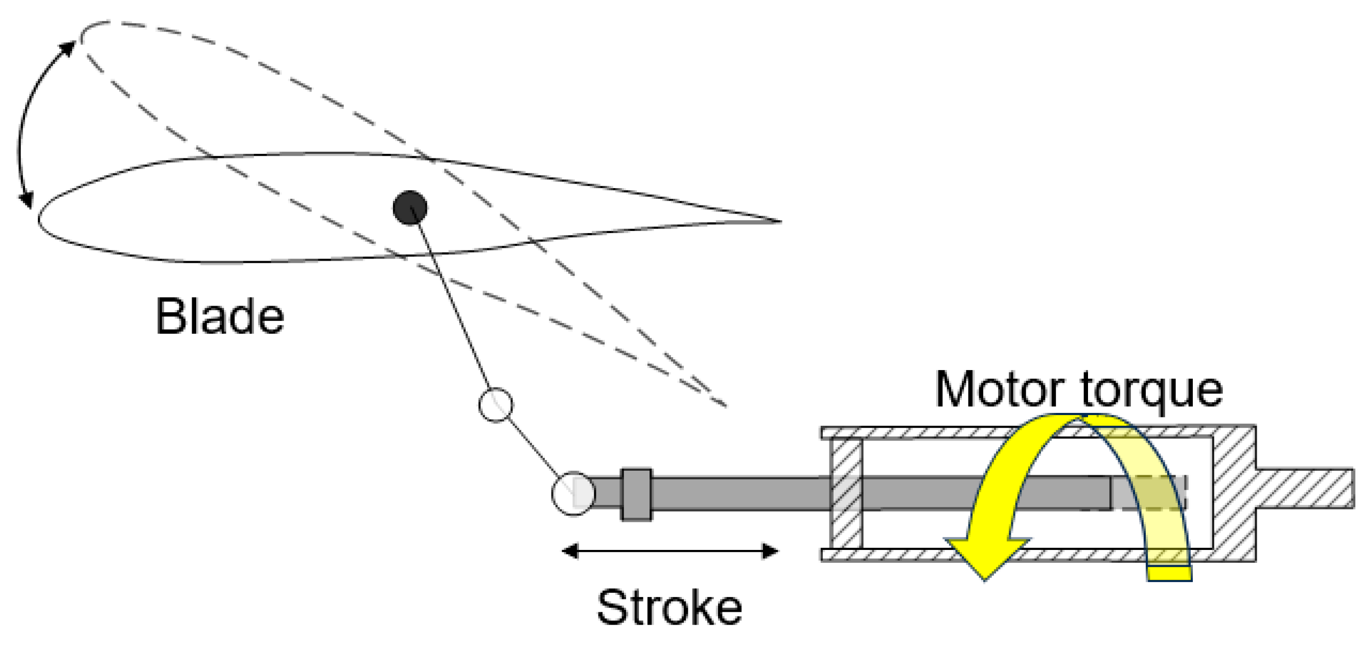
3.2. Multibody Dynamics

Figure 6 and Figure 7 show the operating mechanism of the planetary roller screw and the pitch adjustment system [24]. The EMA for individual blade control controls the linear motion of the screw by rotating the nut and roller, driven by the torque generated from the motor. Additionally, the screw, which undergoes straight reciprocating motion, is designed to adjust the blade pitch angle.
The EMA consists of a housing assembly which protects the internal powertrain system and a roller screw assembly which transmits power generated by the motor to the outside. The housing assembly divided into front, mid, and rear sections is assembled by rods (four EA), and bushings for lateral fixation of the screw are attached to the front of the housing using bolts (six EA). The roller screw assembly consists of a screw, nut, mount, rollers (nine EA) making cloud contact between the screw and nut, and a carrier that maintains their relative positions. Additionally, the axial movement of the roller screw assembly is fixed by bearings (two EA) and retainers.
In addition, there is a permanent magnet synchronous motor (PMSM) that supplies power and a resolver that measures the speed and position of the drive shaft. Figure 8 shows the MBD model composed of joints and force boundary conditions provided by the dynamics analysis program. For external housing assembly shown in Figure 8a, the connectors (four EA), housings (front, mid, and rear), and rod were merged into a single entity, and the front part of the housing was constrained with 6 degrees of freedom based on the mounting conditions. Figure 8b shows the calculation model of roller screw assembly. The linear motion of the screw was simulated with a translational joint, and the bolt-fastened mount and nut were merged under the merge condition shown in Figure 8b.
The acceleration history was applied to the screw to simulate the screw’s stroke, and the motor’s torque over time was replaced with the rotational axial force shown in Figure 9. Meanwhile, Figure 10 shows the roller screw kinematic relation diagram.
Defining the motion of the powertrain through contact conditions involves a significant amount of time and may lead to errors. Therefore, when assuming all components are rigid bodies and that no slipping occurs between the screws, the relative motion between powertrain components can be simulated using a coupler joint. The scale factor for the coupler joint is calculated through Equation (4).
c 1 × v 1 + c 2 × v 2 = 0
where c 1 and v 1 represent the scale factor and velocity of the base element, while c2 and v2 are the scale factor and velocity of the action element. Here, the scale factor of the action element (c2) is assumed to be 1, relative to the base element’s scale factor ( c 1 ) and is calculated based on the relative velocity between the base and action elements. The motion velocities of the nut, rollers, and screw were calculated using Equations (5)–(8) [25].
v p = 1 4 d n ω n = 1 2 d p ω p = 1 2 d s + d p Ω p
x = k θ n
x ˙ = v s = k ω n
k = k ¯ / 2 π
where ω n , ω p , Ω p , and θ n represent the angular velocity of the nut, rotational angular velocity of the roller, revolution angular velocity of the roller, and angular displacement of the nut. Displacement ( x ) and translational speed ( x ˙ ) of the screw indicated in Figure 10 are calculated based on the effective diameters ( d n , d p , and d s ) of the nut, roller, and screw, the lead ( k ¯ ), and screw displacement/angular velocity of the nut ratio ( k ). Table 2 shows the structural parameters of the planetary roller screw. Therefore, the scale factor of the action element (c2) calculated from Equations (5)–(8) between the nut and roller and the roller and screw, as well as the joint conditions for each component, are listed in Table 3. As a result, the orbital and spin speeds of the nut for 1 rev/s are 1.60 rev/s and 0.25 rev/s, respectively, and the reciprocating speed of the driving load is 4.71 mm/s.

3.3. Static Analysis

According to the airworthiness standards for small aircrafts published by the Federal Aviation Administration (FAA) under FAR Part 23 and Part 27, loads are divided into design limit loads (DLLs) and ultimate loads (ULs) from the perspective of evaluating static strength [26,27].
DLLs represent the maximum loads expected during operation, while ULs indicate the value obtained by multiplying the limit loads by the safety factor specified in regulations, considering various uncertainties in the design. In most cases, a factor of 1.5 is applied.
Therefore, in this study, static analysis of the obtained UL conditions from the MBD analysis was conducted. To perform a detailed analysis of the power transmission screw of the EMA, the entire EMA model (model#1) and a reduced model of the roller screw thread (model#2) were distinguished. Figure 11 shows the finite element model and boundary conditions for model#1. For the housing assembly shown in Figure 11a, surface-to-surface conditions were applied to the junctions of the external housing (front, mid, and rear) and the rods, and the ABAQUS Bolt pretension condition was used for the rod axis to fasten the housing. The pretension load for the collar bolt was based on the design bolt load for M 5 specified in the KS B 0233 (ISO 898-1) standard, and a standard bolt tension of 8.12 kN was applied, considering a 10% additional increase for loosening [28].
For the power transmission system of model#1 shown in Figure 11b, the threads of the nut, roller, and screw were removed, and the connecting parts of each component were tied together with tie conditions to constrain the axial fixation. Figure 11c shows the boundary conditions of the EMA. Considering the mounting conditions of the EMA, the front of the housing was fixed with 6 degrees of freedom, and an axial load (UL) was applied to the screw where the blade pitch link is connected. The housing (front, mid, and rear) including the rods was applied to the mechanical properties of aluminum. The material for the roller screw assembly (nut, roller, and screw) is steel#1, and the remaining components were applied to the mechanical properties of steel#2. For purchased items such as bearings and bolts, assuming structural safety based on the specifications from the supplier, rigid elements (R3D4) were used, while other components were applied to hexahedral (C3D8R) and tetrahedral (C3D10) elements typically used in static analysis.
Figure 12 shows the finite element model of model#2. The elements of the reduced model of the roller screw thread were composed of C3D8R, and the area of the screw thread where high equivalent stress was predicted was modeled more densely. Surface-to-surface contact was applied to the threaded contact surfaces of each component, and the outer surface of the nut was fixed with 6 degrees of freedom. Additionally, all degrees of freedom except for movement along the X-axis of the roller and screw were constrained, and a load was applied to the axis of the screw. Assuming that the load is evenly distributed among the rollers (nine EA), the axial load of 586.3 N shown in Figure 12 is calculated by dividing the UL (5276.6 N) by the number of rollers (nine EA). The materials and the number of elements and nodes used in the structural analysis are listed in Table 4.

3.4. Fatigue Analysis

In this study, fatigue analysis was performed using the stress data obtained from the static analysis and the material’s P-S-N curve. According to the fatigue evaluation items specified in the airworthiness standards (FAR Part 23.572), from the perspective of fatigue safety strength, structural failure should not occur for fatigue loads obtained by multiplying the load history for operational conditions by a factor of 1.15. The fatigue load history of model#1 is calculated by multiplying the factor with the load history derived from multibody dynamics analysis.
Additionally, for a conservative fatigue analysis of the power transmission system (model#2) that requires high reliability, a sinusoidal waveform with the maximum fatigue load as its amplitude was selected as the load history, as shown in Figure 13.
In Figure 13, the axial force is applied at the same point where the UL is applied in Figure 12. Additionally, the amplitude shown in Figure 13 is calculated by dividing the drive load of the maximum load (3517.7 N) by the number of rollers (nine EA) and multiplying the result by 1.15.
Meanwhile, the fatigue analysis model is subjected to a multiaxial stress state due to complex component shapes and boundary conditions. Therefore, the Brown–Miller and Morrow algorithms, which are multiaxial fatigue life prediction methods based on the critical plane approach, are employed to calculate the fatigue life [29]. The fatigue life for repeated loads is calculated using Equations (9)–(11) [19,30].
Δ γ m a x 2 + Δ ϵ i 2 = C e N f b + C p N f c
Δ γ m a x 2 = ϵ 1 ϵ 3 2
ϵ i = ϵ 1 + ϵ 3 2
where γ max represents the maximum shear strain, and ε i (i = 1, 3) is the normal strain on each respective interface. Moreover, C e and b are the elastic coefficient and fatigue strength exponent, while C p and c represent the plastic coefficient and fatigue strain exponent. According to the crack initiation approach proposed by Baumel and Seeger, the prediction of the strain–life curve requires only the tensile strength of the material, without the need for considerations such as section contraction or fatigue ductility. The fatigue life of for low-alloy and carbon steels ( BS F ) is calculated through Equations (12)–(16).
Δ γ m a x 2 + Δ ϵ i 2 = C e B S F N f b + C p B S F N f 0.58
C e B S F = 1.412 σ t E
C p B S F = 0.395 φ
where σ t and E represent ultimate tensile strength and young’s modulus.
σ t E 0.003 ,   φ = 1  
σ t E > 0.003 ,   φ = 1.375 125.0 σ t E  
Also, the fatigue life of non-ferrous alloys ( BS n ) is calculated through Equations (17) and (18).
Δ γ m a x 2 + Δ ϵ i 2 = C e B S n N f b + 0.217 N f 0.69
C e B S n = 1.564 σ t E
The fatigue strength exponent ( b ) of Equations (12) and (17) were determined using the values specified in Table 1 for each material. Meanwhile, following Brown–Miller’s critical plane method, the critical angle was increased by 10-degree increments to determine the critical plane where the maximum shear stress occurs. Subsequently, the maximum and minimum principal strains obtained through static analysis were used to calculate the maximum shear strain and normal strain on the critical plane. Based on this theory, the fatigue life of the EMA was calculated.

4. Results

4.1. Multibody Dynamics

Figure 14 shows the results of the MBD analysis and the profile datasheets obtained from the subjective organization. As a result, regular movements similar to sine waves were observed, repeating a total of 8.5 cycles with intervals of 0.13 s. The results of the multibody dynamics analysis were very similar to the profile datasheets. The maximum rotational and revolution speeds of the roller were calculated to be 579.07 and 144.76 rad/s, as shown in Figure 14a,b. The screw goes up and down at a constant period reaching a maximum stroke of 7.8 mm, as shown in Figure 14d. Figure 15 shows the axial reaction force of the linear actuator under the operating condition. The maximum load of 3517.7 N occurred at 1.1 s, and compared with the profile datasheets, there was an approximately 16.4 N difference at the point of maximum load. This is attributed to the inertial load due to the axial acceleration during the reciprocation of the driving load. Therefore, the dynamic behavior of the EMA was analyzed, and the maximum reaction force and load history under operating conditions were employed into FEA.

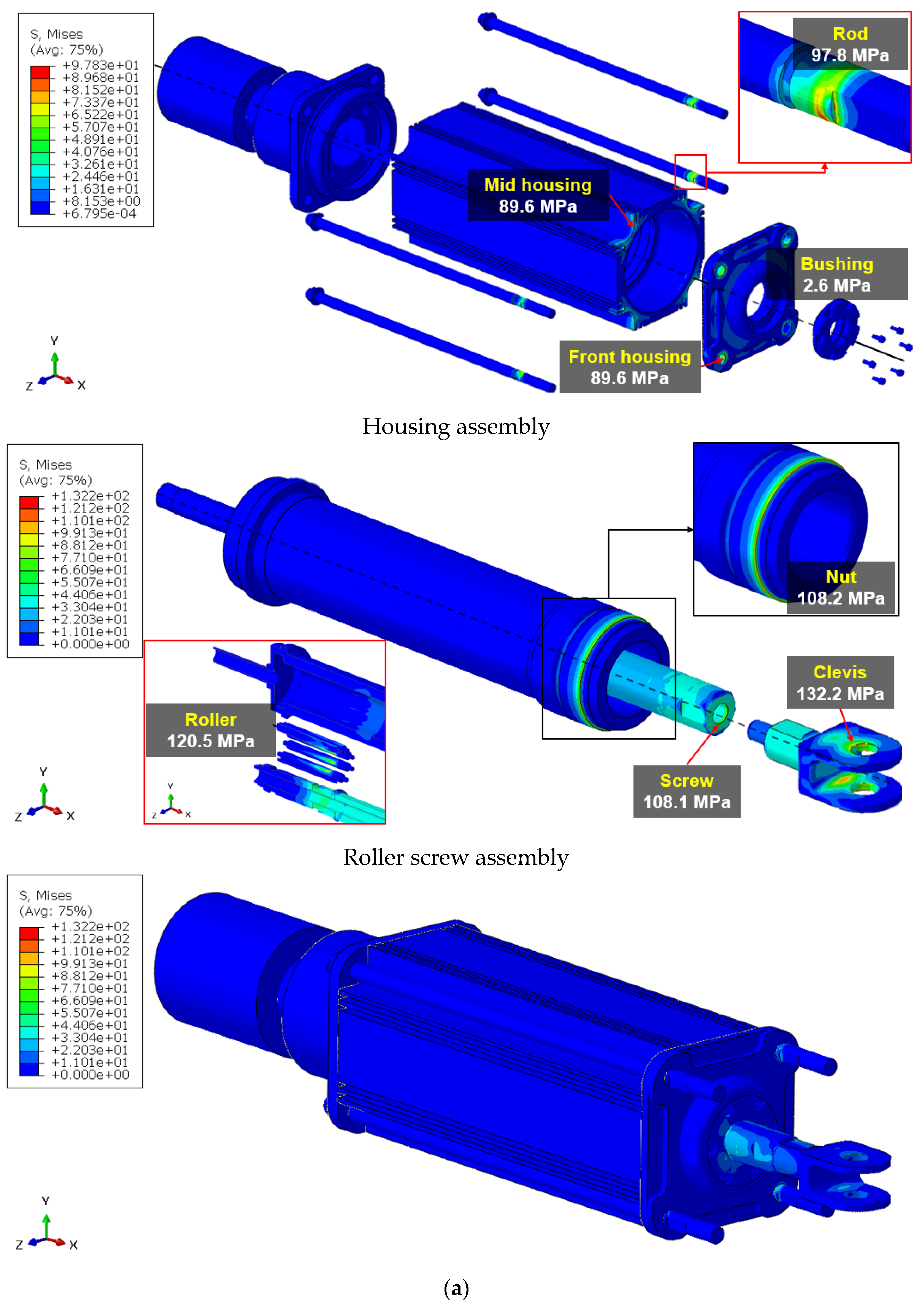
4.2. Static Analysis

Figure 16 shows the von Mises stress distribution under the UL condition derived from the static analysis. Aeronautical technical standards specify that the structure must be capable of supporting the prescribed loads without experiencing detrimental permanent deformation (yield) in terms of strength and deformation (FAR Part 23.305). Therefore, in this study, structural safety was evaluated by calculating the MS based on the von Mises stress under the UL condition, which considered DLLs, a safety factor, and the mechanical properties of the materials. The MS was calculated using Equation (19) [31].
M S = S y σ v 1
where S y and σ v represent the yield strength of the material and the von Mises stress under the UL condition. If the value of the MS is smaller than zero (MS < 0), the design needs to be improved because structural design requirements are not satisfied. Figure 16a shows the von Mises stress distribution of model#1calculated through the static analysis. The calculated maximum von Mises stress of the model#1 (132.2 MPa) occurred at the clevis. Because stress concentration occurred due to the abrupt change in shape and it was at 34% of the yield strength of the applied material (aluminum), therefore resulting in an MS value of 1.9. Furthermore, for the rod and front housing, the maximum von Mises stress values under the UL condition were found to be 97.8 (25%) and 89.6 (56%) MPa, respectively, and the maximum stress occurred in the area where the rod and front housing were in contact with each other. The corresponding MS values were calculated to be 2.9 and 3.3, respectively. Additionally, Figure 16b shows the static analysis results of model #2. the maximum von Mises stress values for the nut, roller, and screw were calculated as 132.8, 114.8, and 168.6 MPa in the regions where each thread contact occurs, as shown in Figure 16b. Additionally, the MS values were found to be 11.8, 13.8, and 9.1. For other components, equivalent stresses were found to be below 30 MPa, confirming structural safety.

4.3. Fatigue Analysis

Figure 17 shows the fatigue life distribution of the EMA under operational conditions as determined through fatigue analysis. According to the criteria provided in FAR, it must be demonstrated that fatigue failure will not occur within the established replacement time for structural components that could be critical in the event of damage, such as the rotor drive system between the engine and rotor hub, the control system, the airframe, landing gear, etc. (FAR Part 23.572).
In this study, a fatigue life of 107 cycles or more, specified as the requirements, was considered as infinite life. For a conservative analysis, a load history of the actuator completing 7.5 reciprocating cycles was defined as 1 cycle. Nonetheless, in the case of the model#1, the fatigue life of all key components was calculated as 107 cycles as shown in Figure 17a, confirming structural safety compared to the typically required fatigue life for aircraft components (106 cycles) [32,33,34,35]. Figure 17b shows the fatigue analysis results for model#2. Specifically, the clevis which showed higher von Mises stress compared to other components in the static analysis, and the conservatively analyzed model#2, both calculated a fatigue life of over 107 cycles, affirming structural integrity under fatigue loads. Therefore, the MS and fatigue life resulting from the structural analysis of the EMA are listed in Table 5. As presented in Table 5, an MS of 1.9 or higher was calculated, Additionally, a fatigue life of 107 cycles was determined. Accordingly, all key components of the EMA were found to be structurally safe against ULs and repeated loads (MoS ≥ 0).

5. Conclusions

In this study, static structural and fatigue safety were evaluated for the EMA for eVTOL. To conduct a conservative fatigue life assessment, a P-S-N curve considering a 1% probability of failure for the applied material was derived. Subsequently, MBD analysis was performed to analyze the structural behavior and derive load data for structural analysis. Based on the calculated forces (reaction force and contact force), the FE-based static analysis was conducted, and static structural safety was evaluated by deriving the margin of safety (MS). Additionally, fatigue safety was evaluated by conducting FEA based on the stress data calculated by the static analysis and the operating profile of the EMA.
As a result, an MS of 0 or higher was calculated for all key components of the EMA, confirming a fatigue life of 107 cycles or more and ensuring both static and fatigue safety. This study thus demonstrates the feasibility of evaluating the structural safety of aircraft components using analytical methods. It is suggested that the structural analysis techniques proposed in this study be considered for future application to substantiate the certification criteria for the structural safety of eVTOL aircraft components using analytical methods.

Author Contributions

Methodology, S.-W.K.; Software, Y.-C.K. and D.-H.K.; Formal analysis, Y.-C.K.; Data curation, D.-H.K.; Writing—original draft, Y.-C.K. and D.-H.K.; Writing—review & editing, S.-W.K.; Supervision, S.-W.K.; Project administration, S.-W.K.; Funding acquisition, S.-W.K. All authors have read and agreed to the published version of the manuscript.

Funding

This research was supported by the Basic Science Research Program through the National Research Foundation of Korea (NRF), funded by the Ministry of Education (No. 2022R1A6A1A03056784), and this work was also supported by the National Research Foundation of Korea (NRF) grant funded by the Korea government (MSIT) (No. 2022R1F1A1069025). This work was supported by the Technology Innovation Program (No.20015907, High reliability electro mechanical actuator development for next generation air mobility), funded by the Ministry of Trade, Industry, and Energy (MOTIE, Korea).

Data Availability Statement

The data presented in this study are available on request from the corresponding author.

Conflicts of Interest

The authors declare no conflict of interest.

References

  1. Schlabe, D.; Lienig, J. Energy management of aircraft electrical systems—state of the art and further directions. In Proceedings of the 2012 Electrical Systems for Aircraft, Railway and Ship Propulsion, Bologna, Italy, 16–18 October 2012; pp. 1–6. [Google Scholar]
  2. Schefer, H.; Fauth, L.; Kopp, T.H.; Mallwitz, R.; Friebe, J.; Kurrat, M. Discussion on Electric Power Supply Systems for All Electric Aircraft. IEEE Access 2020, 8, 84188–84216. [Google Scholar] [CrossRef]
  3. Yokota, K.; Fujimoto, H.; Kobayashi, H. Observer-based Angle of Attack Estimation for Tilt-Wing eVTOL Aircraft. In Proceedings of the 2021 IEEE International Conference on Mechatronics (ICM), Chiba, Japan, 7–9 March 2021; pp. 1–6. [Google Scholar]
  4. Ngo, T.D.; Sultan, C.; VanZwieten, J.H.; Xiros, N.I. Constrained Control of Moored Ocean Current Turbines with Cyclic Blade Pitch Variations. IEEE J. Ocean. Eng. 2021, 46, 594–610. [Google Scholar] [CrossRef]
  5. Chou, T.; Ying, Q.; Qian, Y.; Zhuge, W.; Zhang, Y. Study on Overall Design of a Vertical Take-Off and Landing Unmanned Aerial Vehicle Powered by Electric Ducted Fans. In Proceedings of the ASME 2021 Fluids Engineering Division Summer Meeting. Volume 2: Fluid Applications and Systems; Fluid Measurement and Instrumentation, Online, 10–12 August 2021; Volume 2, pp. 10–12. [Google Scholar]
  6. Giangrande, P.; Madonna, V.; Sala, G.; Kladas, A.; Gerada, C.; Galea, M. Design and Testing of PMSM for Aerospace EMA Applications. In Proceedings of the IECON 2018—44th Annual Conference of the IEEE Industrial Electronics Society, Washington, DC, USA, 21–23 October 2018; pp. 2038–2043. [Google Scholar]
  7. Qiao, G.; Liu, G.; Shi, Z.; Wang, Y.; Ma, S.; Lim, T.C. A review of electromechanical actuators for More/All Electric aircraft systems. Proc. Inst. Mech. Eng. Part C J. Mech. Eng. Sci. 2018, 232, 4128–4151. [Google Scholar] [CrossRef]
  8. Kim, D.H.; Kim, S.W. Evaluation of structural safety of linear actuator for flap control of aircraft. J. Aerosp. Syst. Eng. 2019, 13, 66–73. [Google Scholar]
  9. Kim, D.H.; Kim, S.W. Evaluation of Structural Safety of Critical Design Model of Linear Actuator for Flap Control of Aircraft and Test Rig. Int. J. Aeronaut. Space Sci. 2020, 44, 115–116. [Google Scholar]
  10. Kim, D.H.; Kim, M.G.; Kim, S.W. Structural Behavior of Linear Actuator for Control of Aircraft Flap in Critical Design Phase. Trans. Korean Soc. Mech. Eng. A 2020, 44, 733–744. [Google Scholar] [CrossRef]
  11. Li, X.; Liu, G.; Fu, X.; Ma, S. Review on motion and load-bearing characteristics of the planetary roller screw mechanism. Machines 2022, 10, 317. [Google Scholar]
  12. Lim, D.J.; Yee, K.J. A Study on the Certification System for eVTOL Aircraft. J. Aerosp. Syst. Eng. 2021, 15, 20–29. [Google Scholar]
  13. Choi, J.W.; Hwang, C.J. Status and Approach on Certification Basis of eVTOL for Urban Air Mobility. In Proceedings of the Korean Society for Aeronautical and Space Sciences Fall Conference, Jeju, Republic of Korea, 20–23 November 2019; pp. 621–622. [Google Scholar]
  14. Johnson, W.; Silva, C. NASA concept vehicles and the engineering of advanced air mobility aircraft. Aeronaut. J. 2022, 126, 59–91. [Google Scholar] [CrossRef]
  15. Fatemi, A.; Shamsaei, N. Multiaxial fatigue: An overview and some approximation models for life estimation. Int. J. Fatigue 2011, 33, 948–958. [Google Scholar] [CrossRef]
  16. Wang, C.H.; Brown, M.W. A path-independent parameter for fatigue under proportional and non-proportional loading. Fatigue Fract. Eng. Mater. Struct. 1993, 16, 1285–1297. [Google Scholar]
  17. Fatemi, A.; Socie, D.F. A critical plane approach to multiaxial fatigue damage including out-of-phase loading. Fatigue Fract. Eng. Mater. Struct. 1988, 11, 149–165. [Google Scholar]
  18. Smith, K.N.; Watson, P.; Topper, T.H. A stress-strain function for the fatigue of metals. J. Mater. 1970, 5, 767–778. [Google Scholar]
  19. Miller, K.J.; Brown, M.W. Multiaxial fatigue: A brief review. Fracture 1984, 84, 31–56. [Google Scholar]
  20. Xue, L.; Shang, D.G.; Li, D.H.; Li, L.J.; Liu, X.D.; Chen, H. Equivalent energy-based critical plane fatigue damage parameter for multiaxial LCF under variable amplitude loading. Int. J. Fatigue 2020, 131, 105350. [Google Scholar] [CrossRef]
  21. Huang, H.Z.; Liu, D.; Li, Y.F.; Bai, S. Multiaxial fatigue life prediction of an aero-engine turbine shaft with a modified critical plane-based model. In Proceedings of the 12th International Conference on Quality, Reliability, Risk, Maintenance, and Safety Engineering, Sichuan, China, 27–30 July 2022; pp. 1807–1811. [Google Scholar]
  22. Kwofie, S. An exponential stress function for predicting fatigue strength and life due to mean stresses. Int. J. Fatigue 2001, 23, 829–836. [Google Scholar] [CrossRef]
  23. Choi, J.H.; Koo, J.M.; Seok, C.S.; Song, W.K. Evaluation of Fatigue Life Characteristic of a Real Waterwork Pipe Using the Probability Density Function. Trans. Korean Soc. Mech. Eng. A 2008, 32, 707–712. [Google Scholar] [CrossRef]
  24. Jones, M.H.; Velinsky, S.A.; Lasky, T.A. Dynamics of the planetary roller screw mechanism. J. Mech. Robot. 2016, 8, 014503. [Google Scholar] [CrossRef]
  25. Jin, J.H. Dynamic Models of Blade Pitch Control System Driven by Electro-Mechanical Actuator. J. Aerosp. Syst. Eng. 2022, 50, 111–118. [Google Scholar]
  26. FAA Federal Aviation Administration. Part 23—Airworthiness Standards: Normal Category Airplanes—Amendment 1-49; FAA Federal Aviation Administration: Washington, DC, USA, 1996.
  27. FAA Federal Aviation Administration. Part 27—Airworthiness Standards: Normal Category Rotorcraft—Amendment 1-37; FAA Federal Aviation Administration: Washington, DC, USA, 1999.
  28. ISO 898-1; Mechanical Properties of Fasteners Made of Carbon Steel and Alloy Steel-Part 1: Bolts, Screws and Studs with Specified Property Classes-Coarse Thread and Fine Pitch Thread. International Organization for Standardization: London, UK, 2013.
  29. Brown, M.W.; Miller, K.J. A theory for fatigue failure under multiaxial stress-strain conditions. Proc. Inst. Mech. Eng. 1973, 187, 745–755. [Google Scholar] [CrossRef]
  30. Fonseca Junior, T.M.I.; Magnabosco, R. Evaluation of methods for estimating fatigue properties applied to stainless steels and aluminum alloys. Tecnol. Em Metal. Mater. Mineração 2013, 9, 284–293. [Google Scholar] [CrossRef]
  31. Kim, D.H.; Kim, Y.C.; Kim, S.W. Numerical Evaluation of Structural Safety of Linear Actuator for Flap Control of Aircraft Based on Airworthiness Standard. Aerospace 2021, 8, 104. [Google Scholar] [CrossRef]
  32. Thawre, M.M.; Verma, K.K.; Jagannathan, N.; Peshwe, D.R.; Paretkar, R.K.; Manjunatha, C.M. Effect of ply-drop on fatigue life of a carbon fiber composite under a fighter aircraft spectrum load sequence. Compos. Part B Eng. 2016, 86, 120–125. [Google Scholar] [CrossRef]
  33. Abdelhafeez, A.M.; Soo, S.L.; Aspinwall, D.K.; Dowson, A.; Arnold, D. The influence of burr formation and feed rate on the fatigue life of drilled titanium and aluminium alloys used in aircraft manufacture. CIRP Ann. 2018, 67, 103–108. [Google Scholar] [CrossRef]
  34. Al-Bahkali, E.A.; Elkenani, H.; Souli, M. Failure and fatigue life due to random vibration in aircraft applications. In Multiphysics Simulations in Automotive and Aerospace Applications; Academic Press: Cambridge, MA, USA, 2021; pp. 131–154. [Google Scholar]
  35. Nicholas, T. Critical issues in high cycle fatigue. Int. J. Fatigue 1999, 21, 221–231. [Google Scholar] [CrossRef]
Figure 1. Fatigue fracture mechanisms.
Aerospace 11 00091 g001
Figure 2. Procedure for critical plane-based multiaxial fatigue analysis.
Aerospace 11 00091 g002
Figure 3. Rotation of the principal plane.
Aerospace 11 00091 g003
Figure 4. Procedure of fatigue analysis.
Aerospace 11 00091 g004
Figure 5. P-S-N curves: (a) aluminum; (b) steel#1; (c) steel#2.
Aerospace 11 00091 g005
Figure 6. Configuration of planetary roller screw mechanism.
Aerospace 11 00091 g006
Figure 7. Working principle of individual blade control.
Aerospace 11 00091 g007
Figure 8. Multibody dynamics model and boundary conditions of EMA.
Aerospace 11 00091 g008
Figure 9. The operating profile of the EMA.
Aerospace 11 00091 g009
Figure 10. Roller screw kinematic relation diagram.
Aerospace 11 00091 g010
Figure 11. The calculation model and the boundary conditions of model#1 used in finite element analysis.
Aerospace 11 00091 g011
Figure 12. The calculation model and the boundary conditions of model#2 used in finite element analysis.
Aerospace 11 00091 g012
Figure 13. The load history of roller screw assembly.
Aerospace 11 00091 g013
Figure 14. Results of multibody dynamics analysis: (a) rotational angular velocity of the roller; (b) revolution angular velocity of the roller; (c) angular velocity of the nut; (d) stroke of the screw.
Aerospace 11 00091 g014
Figure 15. The reaction forces of the actuation rod over time.
Aerospace 11 00091 g015
Figure 16. The von Mises stress distribution of the components of the linear actuator obtained from the static analysis.
Aerospace 11 00091 g016aAerospace 11 00091 g016b
Figure 17. The fatigue life (logarithmic scale) of the components of the linear actuator obtained from the fatigue analysis.
Aerospace 11 00091 g017aAerospace 11 00091 g017b
Table 1. Mechanical and fatigue properties of materials used in EMA.
PropertiesMaterials
AluminumSteel#1Steel#2
Elastic modulus (GPa)69.8193210
Poisson’s ratio0.330.290.30
Yield strength (MPa)275.8215.01700
Tensile strength (MPa)310.3505.02300
Fatigue strength coefficient, σ f 872.1 (P = 50%)
815.2 (P = 1%)
326.7 (P = 50%)
277.0 (P = 1%)
701.3 (P = 50%)
689.9 (P = 1%)
Fatigue strength exponent, b −0.145−0.063−0.054
Fatigue strength
(107 cycles, MPa)
84.5 (P = 50%)
79.0 (P = 1%)
118.3 (P = 50%)
100.3 (P = 1%)
295.9 (P = 50%)
291.1 (P = 1%)
Table 2. Structural parameters of planetary roller screw.
Parameter NameSymbolValueUnit
Effective diameter of screw d s 21mm
Effective diameter of roller d p 7mm
Effective diameter of nut d n 35mm
Pitchpz3.333mm
Number of rollers-9-
Table 3. Boundary conditions used in the multibody dynamics analysis.
TypeBase ElementsAction ElementsBoundary ConditionsRemark
MergeHousingRod (4EA)--
MergeHousingConnector (4EA)--
MergeNutMount--
RevoluteHousingNutX-axis rotation-
RevoluteHousingCarrierX-axis rotation-
RevoluteCarrierRollersX-axis rotation-
TranslateHousingScrewX-axis translation-
CouplerRevolute
(nut)
Revolute
(carrier)
Scale
c2 = 1.6
ω n : Ω p = 1.60:1
CouplerRevolute
(carrier)
Revolute
(roller)
Scale
c2 = 0.25
Ω p : ω p = 0.25:1
CouplerRevolute
(roller)
Translate
(screw)
Scale
c2 = 4.71
ω p : x ˙ = 4.71:1
Table 4. The materials and the number of elements and nodes used in the structural analysis.
Parameter NameComponentsMaterialsThe Number of
Elements and Nodes
Model#1HousingsAluminum975,204/1,336,435
Clevis79,544/115,990
Rod119,474/169,646
BushingSteel#1108,601/160,171
Screw130,280/180,784
Rollers73,120/79,507
Nut97,334/116,358
RetainerSteel#25686/13,372
Carrier3240/4761
Model#2ScrewSteel#1283,611/405,910
Rollers432,119/604,546
Nut606,813/858,098
Table 5. The margin of safety and fatigue life for components of EMA.
ComponentsStatic AnalysisFatigue Analysis
MS
(von Mises Stress)
Fatigue Life
(Cycles)
Model#1Housings3.3
(89.6 MPa)
107
Clevis1.9
(132.2 MPa)
Rod2.9
(97.8 MPa)
Bushing645.3
(2.6 MPa)
Screw14.7
(108.1 MPa)
Rollers13.1
(120.5 MPa)
Nut14.7
(108.2 MPa)
Retainer338.3
(1.4 MPa)
Carrier1806.6
(0.3 MPa)
Model#2Screw9.1
(168.6 MPa)
107
Rollers13.8
(114.8 MPa)
Nut11.8
(132.8 MPa)
Disclaimer/Publisher’s Note: The statements, opinions and data contained in all publications are solely those of the individual author(s) and contributor(s) and not of MDPI and/or the editor(s). MDPI and/or the editor(s) disclaim responsibility for any injury to people or property resulting from any ideas, methods, instructions or products referred to in the content.

