Next Article in Journal
Research on Engine Thrust and Load Factor Prediction by Novel Flight Maneuver Recognition Based on Flight Test Data
Next Article in Special Issue
Performance Analysis of Inter-Satellite and Satellite-Ground Communication: A Report on Flight Data for a Low Earth Orbit CubeSat
Previous Article in Journal
Autonomous Optimal Absolute Orbit Keeping through Formation Flying Techniques
Previous Article in Special Issue
A High-Resolution Mass Spectrometer for the Experimental Study of the Gas Composition in Planetary Environments: First Laboratory Results
 
 
aerospace-logo
Article Menu

Article Menu

Article

Data Downloaded via Parachute from a NASA Super-Pressure Balloon

by
Ellen L. Sirks
1,2,*,†,
Richard Massey
1,*,†,
Ajay S. Gill
3,
Jason Anderson
1,
Steven J. Benton
4,
Anthony M. Brown
1,
Paul Clark
1,
Joshua English
1,
Spencer W. Everett
5,
Aurelien A. Fraisse
4,
Hugo Franco
6,
John W. Hartley
7,
David Harvey
8,
Bradley Holder
9,
Andrew Hunter
1,
Eric M. Huff
5,
Andrew Hynous
10,
Mathilde Jauzac
1,
William C. Jones
4,
Nikky Joyce
1,
Duncan Kennedy
1,
David Lagattuta
1,
Jason S.-Y. Leung
3,
Lun Li
4,7,
Stephen Lishman
1,
Thuy Vy T. Luu
4,
Jacqueline E. McCleary
11,
Johanna M. Nagy
12,
C. Barth Netterfield
3,13,
Emaad Paracha
13,
Robert Purcaru
14,
Susan F. Redmond
4,
Jason D. Rhodes
5,
Andrew Robertson
5,
L. Javier Romualdez
7,
Sarah Roth
10,
Robert Salter
6,
Jürgen Schmoll
1,
Mohamed M. Shaaban
13,15,
Roger Smith
16,
Russell Smith
5,
Sut Ieng Tam
17 and
Georgios N. Vassilakis
11
add Show full author list remove Hide full author list
1
Department of Physics, Durham University, South Road, Durham DH1 3LE, UK
2
School of Physics, The University of Sydney and ARC Centre of Excellence for Dark Matter Particle Physics, Sydney, NSW 2006, Australia
3
Dunlap Institute for Astronomy and Astrophysics, University of Toronto, 50 St. George Street, Toronto, ON M5S 3H4, Canada
4
Department of Physics, Princeton University, Jadwin Hall, Princeton, NJ 08544, USA
5
Jet Propulsion Laboratory, California Institute of Technology, 4800 Oak Grove Drive, Pasadena, CA 91011, USA
6
Columbia Scientific Balloon Facility, 1510 Farm Road 3224, Palestine, TX 75803, USA
7
StarSpec Technologies Inc., Unit C-5, 1600 Industrial Road, Cambridge, ON N3H 4W5, Canada
8
Laboratoire d’Astrophysique, EPFL, Observatoire de Sauverny, 1290 Versoix, Switzerland
9
University of Toronto Institute for Aerospace Studies (UTIAS), 4925 Dufferin Street, Toronto, ON M3H 5T6, Canada
10
NASA Wallops Flight Facility, Balloon Program Office, 34200 Fulton St., Wallops Island, VA 23337, USA
11
Department of Physics, Northeastern University, 360 Huntington Ave., Boston, MA 02115, USA
12
Department of Physics, Washington University in St. Louis, 1 Brookings Drive, St. Louis, MO 63130, USA
13
Department of Physics, University of Toronto, 60 St. George Street, Toronto, ON M5S 1A7, Canada
14
Division of Engineering Science, 40 St. George Street, Room 2110, Toronto, ON M5S 2E4, Canada
15
Palantir Technologies, 1875 Lawrence St., Denver, CO 80202, USA
16
California Institute of Technology, 1200 E. California Blvd., Pasadena, CA 91125, USA
17
Academia Sinica Institute of Astronomy & Astrophysics, No. 1, Sec. 4, Roosevelt Road, Taipei 10617, Taiwan
*
Authors to whom correspondence should be addressed.
These authors contributed equally to this work.
Aerospace 2023, 10(11), 960; https://doi.org/10.3390/aerospace10110960
Submission received: 28 September 2023 / Revised: 27 October 2023 / Accepted: 30 October 2023 / Published: 14 November 2023
(This article belongs to the Special Issue Space Telescopes & Payloads)

Abstract

:
In April 2023, the superBIT telescope was lifted to the Earth’s stratosphere by a helium-filled super-pressure balloon to acquire astronomical imaging from above (99.5% of) the Earth’s atmosphere. It was launched from New Zealand and then, for 40 days, circumnavigated the globe five times at a latitude 40 to 50 degrees south. Attached to the telescope were four “drs” (Data Recovery System) capsules containing 5 TB solid state data storage, plus a gnss receiver, Iridium transmitter, and parachute. Data from the telescope were copied to these, and two were dropped over Argentina. They drifted 61 km horizontally while they descended 32 km, but we predicted their descent vectors within 2.4 km: in this location, the discrepancy appears irreducible below ∼2 km because of high speed, gusty winds and local topography. The capsules then reported their own locations within a few metres. We recovered the capsules and successfully retrieved all of superBIT’s data despite the telescope itself being later destroyed on landing.

1. Introduction

The Super-pressure Balloon-borne Imaging Telescope [1] (superBIT) was raised to ∼33 km altitude by nasa’s 18.8 million cubic foot super-pressure balloon 728NT (https://www.csbf.nasa.gov/map/balloon10/flight728NT.htm). It was launched on 16 April 2023 from Wanaka, New Zealand, was carried east by seasonal polar vortex winds [2], circumnavigated the Earth ∼5.5 times, then landed in Argentina on 25 May 2023. During this flight, the telescope acquired deep optical and near-UV imaging of galaxy clusters and other astronomical objects [3]. Early in the mission, data were transmitted to ground stations via Starlink and tdrss satellite communication links. However, the Starlink connection was lost on 1 May 2023, and tdrss became unstable on 24 May 2023. The root cause for each failure remains under investigation. All of the data was stored on board, as well as on redundant sets of solid-state drives within drop packages. Several copies of the full dataset were released via parachute prior to the termination of the flight and were safely recovered. The superBIT payload was entirely destroyed upon landing, and although, in this case, the data were eventually recovered from the remains of the onboard drives, the use of parachutes to ensure the safe recovery of the data proved invaluable.
Four Data Recovery System (drs) capsules were attached to the telescope before launch. As well as a parachute, each included 5 TB solid state data storage, a Global Navigation Satellite System (gnss) receiver so it could work out its location, and an Iridium Short-Burst Data (sbd) transceiver, so it could report its location to the recovery team [4] (and receive commands to, e.g., turn on or off a beeper). Two drss were released, and both were successfully recovered with data intact.
In this article, we describe upgrades (since the first test of a drs during a superBIT engineering flight in 2019) to their release mechanism, communications with the telescope, and thermal control. We describe the performance of that hardware during operations and the performance of software that we use to predict their decent trajectory. Accurate predictions of the descent vector are essential in choosing a safe landing zone. Neither the trajectory of the main telescope payload nor the parachute is actively controlled, but the timing of the release can be chosen so that the drs lands in an area that is unpopulated for safety but near a road to facilitate recovery.
Our hardware design (https://github.com/PaulZC/Data_Recovery_System) and software (https://github.com/EllenSirks/pyBalloon) are both open-source. Their success inspired nasa’s ‘floating dragon’ Balloon Challenge (https://floatingdragon.nianet.org/). Following this programme, a similar capability to download data or small physical samples will be made available by nasa to all future super-pressure balloon teams to insure against the loss of communications, loss of payload, or destruction of payload upon landing. Our experience suggests that teams should take the offer.

2. Upgraded Hardware Design

Each drs capsule comprised a Raspberry Pi 3B attached to a custom 300 mm × 125 mm printed circuit board (pcb; see Figure 1). The capsules were powered by switchable 24 V DC from the main payload while they were attached, then by two internal 9 V lithium batteries after release. These batteries were the only components of the drs that could be considered potentially hazardous. However, they were compliant with safety test criteria T1–T8 defined in Section 38.3 of [5]. The drs used a geared pincer mechanism to hold on to a loop of nylon cable tie underneath the main payload. After coordination with local air traffic control, we issued a sequence of three commands (to prevent errors and fault propagation) that used a servo inside the drs to open the pincer, allowing the drs to drop away.
Each drs was enclosed in a 3D-printed cpe hard plastic case and a closed-cell foam shell (see Figure 2). One case was printed in pla, which also works fine but is harder to handle because it is brittle. The foam shell could absorb impacts and add a degree of waterproofing, which proved useful when one drs landed in snow. It was manufactured by pouring liquid PU expanding foam mix into a pill-shaped mould a few millimetres less than 6” in diameter, lined with a chicken roasting bag to create a waterproof outer surface on which contact details can be written [6]. The total mass including the parachute was 1.28 kg.

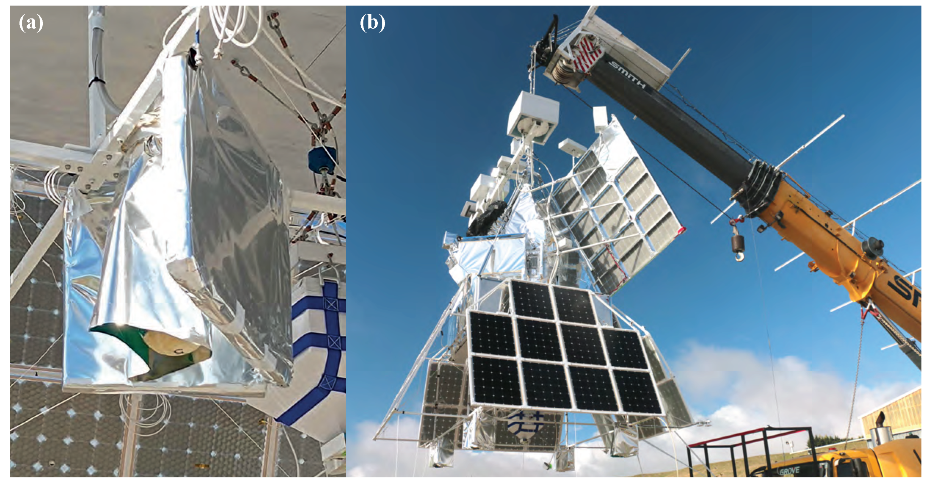
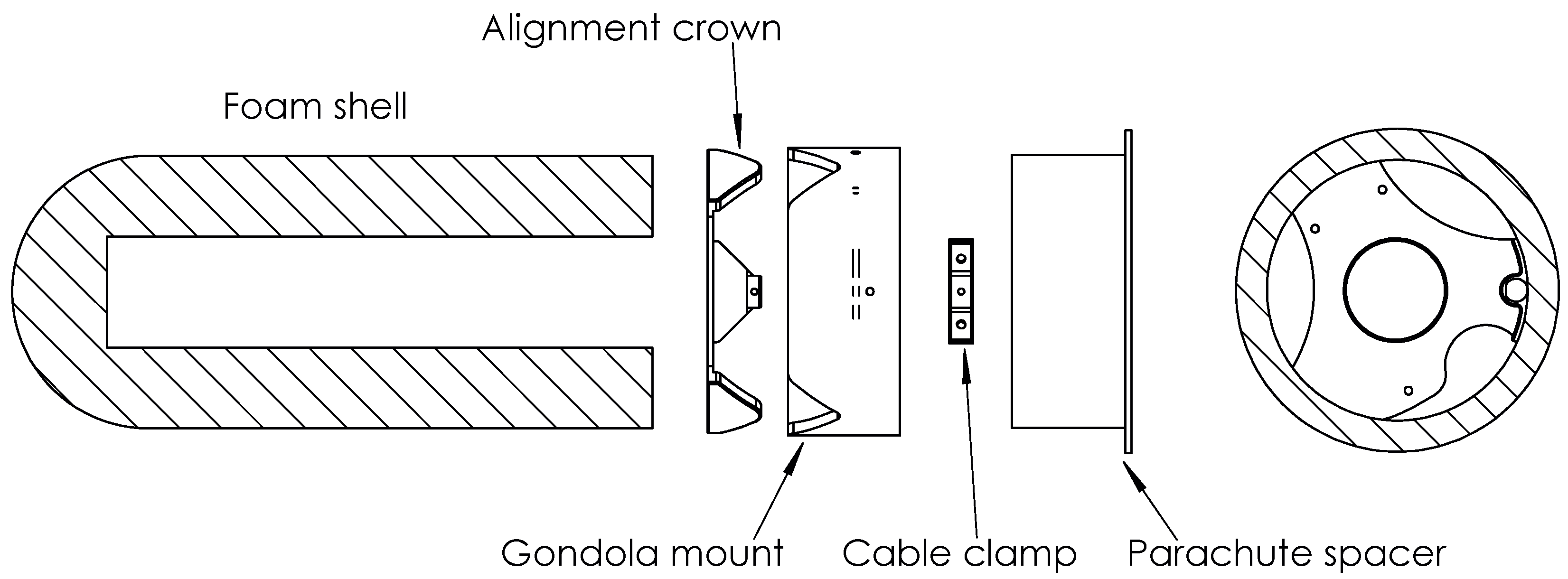
2.1. Alignment and Attachment to the Main Payload

To prevent the drs from swinging while hanging under the payload during the 2019 test flight, it was sheathed inside a section of 6” plastic drainpipe. This worked flawlessly at altitude when two drs capsules were successfully released. However, during subsequent testing in a thermal vacuum chamber, the foam sometimes expanded and became wedged inside the pipe to drop only when surrounding air pressure increased. To mitigate the risk of a drs becoming wedged at altitude, we remove the pipe and attached a 3D-printed petg ‘crown’ to the top of the drs (see Figure 2). This fit into an inverted crown that was fixed to the main gondola. The crowns were kept together, and the drs was held secure by pulling the cable tie taut.
A second pincer mechanism held a 4 foot parachute folded inside a spacer above the drs. This size parachute yields a terminal velocity ∼4 m s 1 . This was fast enough to reduce the downrange travel distance (hence, uncertainty in the predicted landing spot, which allowed us to avoid populated areas) while keeping kinetic energy comfortably below a 15 J safety requirement to note cause serious injury or damage.

2.2. Hardwired Ethernet to the Main Payload

It was possible for the drs to communicate with the main payload via the Raspberry Pi’s built-in WiFi. This worked successfully throughout the 2019 test flight. However, the launch of that flight was delayed because of radio interference. After much investigation, it turned out that the interference had nothing to do with WiFi, but it took time to rule out that possibility and to then look for the real source. To militate against future risk of delays and to enable operation on payloads that require radio silence for scientific measurements [7] (e.g., SPIDER;), we use hardwired Ethernet for the 2023 science flight. Inside the drs, this involved a standard Ethernet cable plugged into the Pi’s Ethernet socket. Outside the drs, two twisted cable pairs were routed to a switch on superBIT, which acted as a dns server.
The six wires (four for Ethernet and two for power) joined at zero-extraction force connectors (Smiths Interconnect Hypertac® connectors, part numbers D02PB906FSTAH and D02PB906MSTH) that would separate easily when the drs was released. Two-pin versions of these connectors worked well during the test flight, but we found that versions with more pins did not sit well and occasionally became disconnected during testing. We, therefore, used grub screws to fix half of the solid connector inside the crown and half in the gondola mount so they would be held together until release.

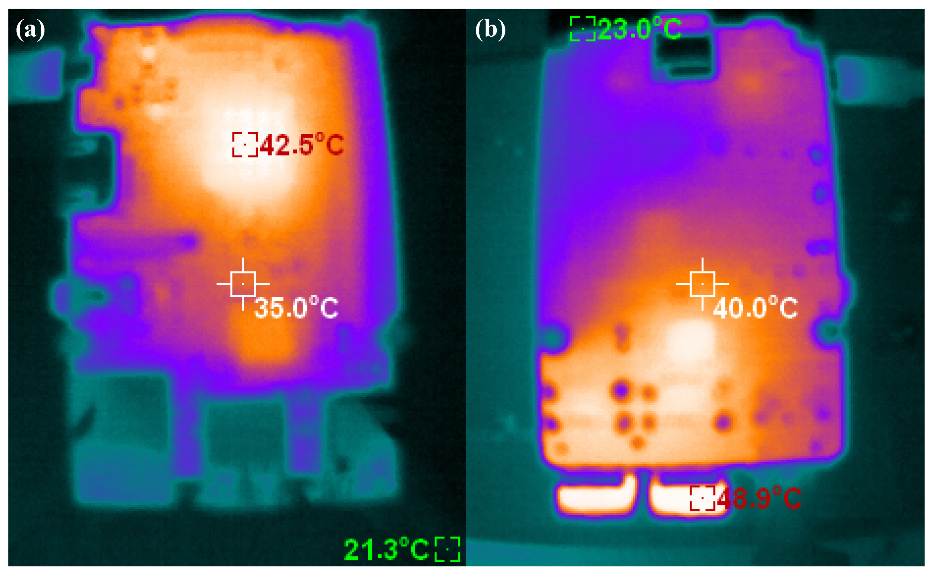
2.3. Thermal Management
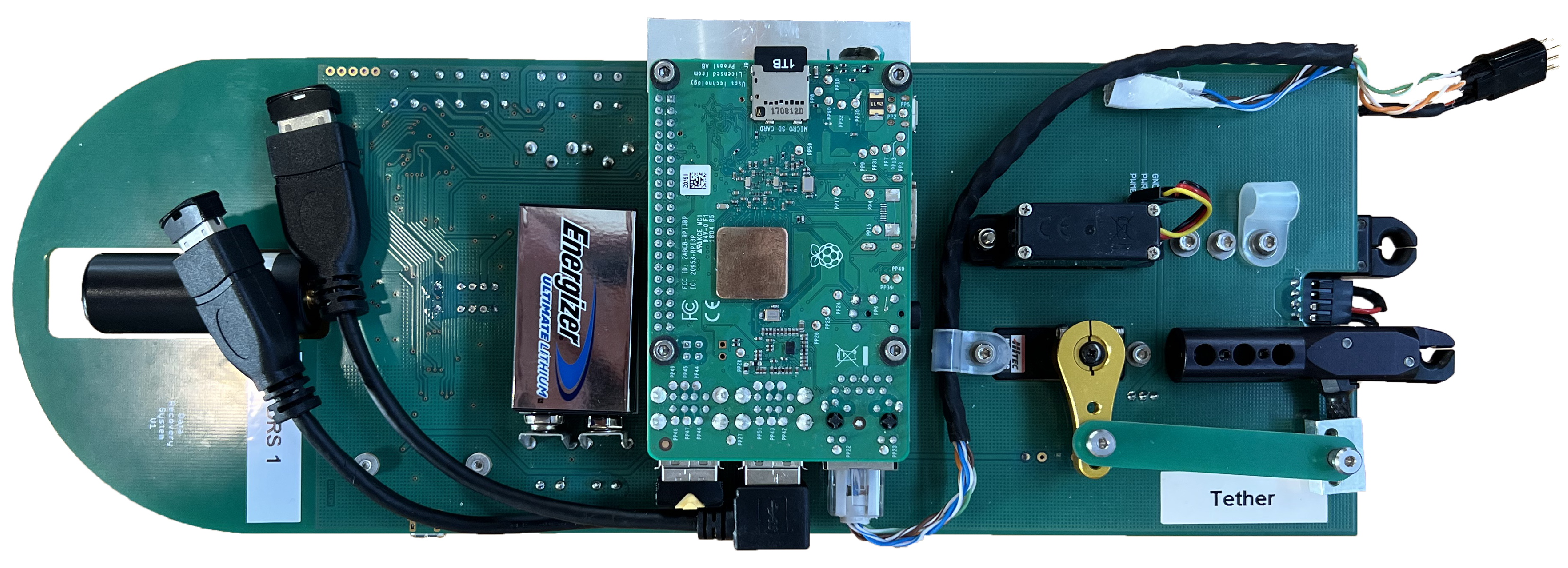
During the 2019 engineering flight, each drs worked for only ∼15 min at a time before overheating and shutting down until it naturally cooled. Subsequent testing in a room temperature lab showed two main hot spots (see Figure 3). Assuming a thermal emissivity coefficient e = 0.95 , the main cpu would reach 42.5  C while executing a simple Python script (the Raspberry Pi itself was reporting a cpu temperature of 49.4  C), and the usb sockets would reach 48.9  C when a 5 GB file was written to an sd card in a small sd card reader. Achieving robust operation during the 2023 science flight required mitigations for both.
To cool the main cpu, we milled a 53 g aluminium heat sink/radiator that sits between the Raspberry Pi and the pcb. It was held against the cpu by a spring glued to the pcb, and contact was ensured with thermal paste. The aluminium block extended through a 56 mm × 14 mm hole in the plastic case, ending flush with that, and was covered with Mylar tape to increase its infrared emissivity. The heat was radiated to space through a hole in the foam shell that was cut by hand (using an indentation in the mould to align it). The ambient temperature in the stratosphere is 40 C [8]. For what it is worth, we also stuck a thin, off-the-shelf copper radiator to the ram chip on the back.
To reduce heat production at the usb sockets, we used two 6” usb extension cables to relocate two sd card readers (they ended up sitting roughly behind the microcontroller).
We also operated each drs on a 5 min on–20 min off rota: powering up each in turn, copying data, then powering down. During a typical cycle during the night (day), the cpu temperature would increase by 3.0 ± 0.3  C (3.7 ± 1.0  C) in 5 min (see Figure 4). On one occasion during night 13, drs1 was powered for two cycles, and its temperature rose 14.7  C (from 11.6 C to 3.1  C) in 30 min. It continued operating throughout this time and cooled half-way back to the same temperature as the others in approximately 2 h. We do not know why drs1 ran at 8.2 ± 8.6 C ( 4.7 ± 11.2 C) during the night (day), consistently a few degrees warmer than drs2 at 11.4 ± 8.1 C ( 1.0 ± 10.7 C) and drs5 at 11.9 ± 7.4 C ( 1.2 ± 10.6 C).
Before launch, four drs capsules were mounted underneath the rest of the payload (see Figure 5). They were oriented with their radiators towards the front of the telescope (which was never allowed to point towards the Sun) and enclosed by a loose skirt of Mylar, the inside of which was aluminised except for a ∼45 pleat near the radiator. On two sides, an additional sunshield of foam wrapped in aluminised Mylar also protected the drss from incidental knocks. drs1 was at the back left, drs2 at the back right, drs3 at the front right, and drs5 at the front left (drs4 was our flight spare). Power and Ethernet cables were routed from each drs up to superBIT.

2.4. Data Storage

Each drs was fitted with 5 × 1  TB MicroSDXC cards: one in the internal slot that includes the operating system and four in usb card readers. We set these up as independent drives (rather than raid to further reduce thermal load) and copy data to one of the sd cards at a time, beginning with those mounted in a usb socket. An rsync script was not sufficient because the sd cards were independent. Instead, whenever the Pi booted, a custom script compared files on the payload with those on the drs (matching name and size because some files, such as instrument timestreams, continually grow) and copied new data to an sd card with sufficient space. superBIT’s rate of data acquisition was sufficiently slow that we could have duplicated all the data to second sd cards on every drs but, with so many backups already, we chose not to.
We tested MicroSDXC cards from several manufacturers before the flight. Resilience is more important than speed in this context, and we found considerable variation in cards’ abilities to withstand a harsh environment. SanDisk Ultra (A1 UHS-I Class 10 U1) and SanDisk Extreme (A2 UHS-I Class 10 U3 V30) cards worked reliably throughout our tests and the flight. Two different Integral (A2 UHS-I Class 10 U3 V30) cards showed intermittent faults during testing: when used to house the operating system, the Pi would occasionally require power cycling to boot. After a few early problems, this was not reproducible, so we flew two drss with SanDisk Ultra sd cards and two with Integral sd cards. All our Lexar (LMSPLAY001T-BNNAG) cards failed during testing, so these were discarded.

2.5. One Failure on Launch

One drs onboard superBIT stopped responding immediately after launch. It is now impossible to determine why, but we suspect that the zero-extraction force connection became misaligned by the launch shock. It was one of the capsules using an Integral sd card that may have also caused problems, but we power cycled it many times without response. All three other drs capsules worked reliably for the entire flight or until they were released.

3. Descent and Recovery

We initially intended to release one drs capsule around mission day 40, 60, 80, and 100, whenever superBIT passed over land, to mitigate the risk of the payload and all its onboard data being lost at sea. superBIT did indeed pass over Chile and Argentina on mission day 40 (25 May 2023). However, in the early hours of the morning, it became apparent that the main payload would need to descend later that day because of reduced communications bandwidth and a weather forecast indicating a southerly trajectory away from further land crossings. After finishing the night’s observations and coordinating with local air traffic control, we released (not one but) two drs capsules over Santa Cruz Province, Argentina. This strategy ensured that independent, redundant sets of data would be available both on board and separated from the main payload.

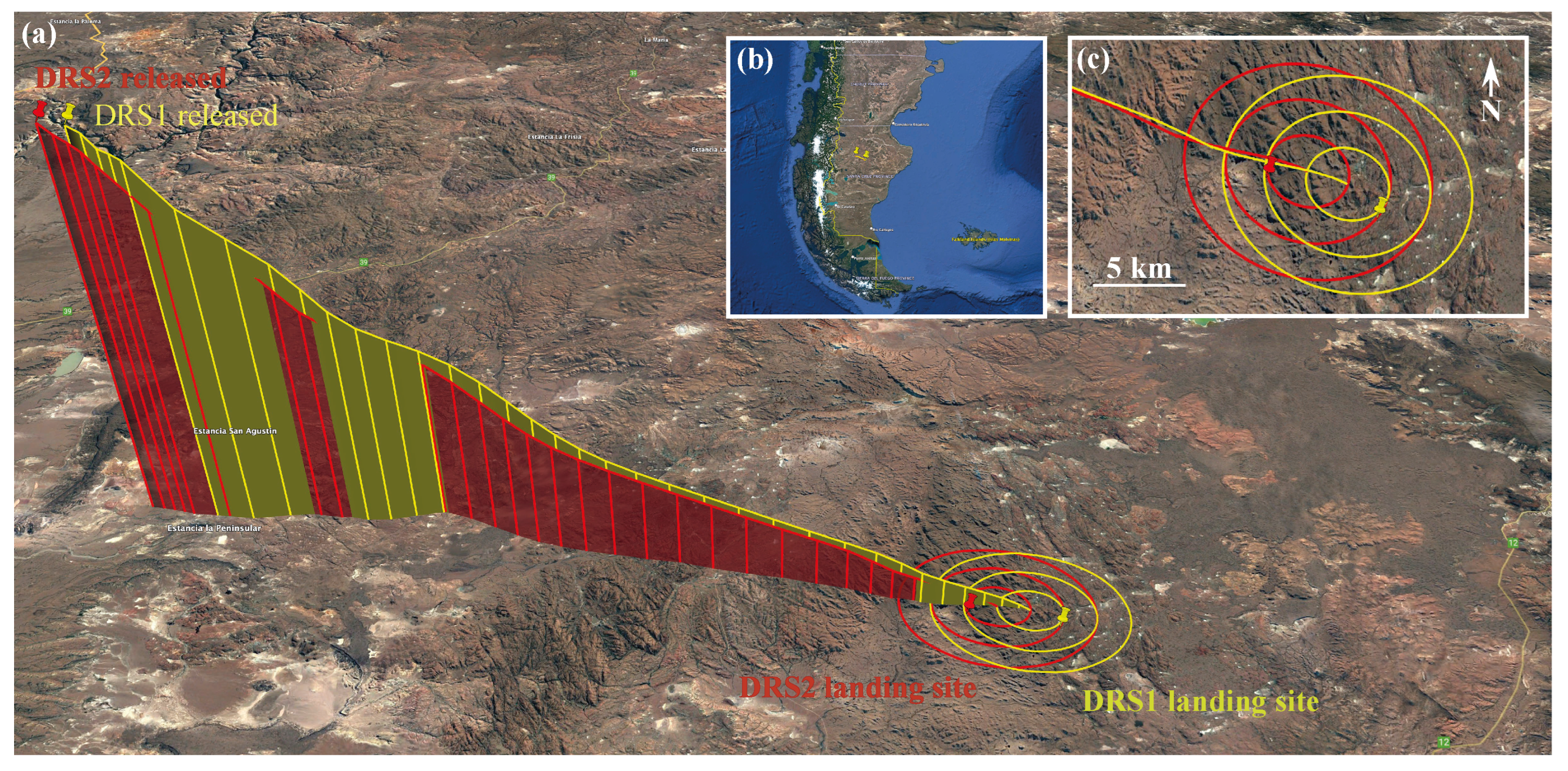
3.1. Release Time and Location

We attempted to release two drs capsules nearly simultaneously so they would land close to each other to simplify recovery. Low-latency communications with the payload had been lost, so we were forced to send release commands via Iridium sbd. We transmitted the two commands on independent channels. However, commands are queued and arrive after an unpredictable delay.
Contemporaneous logs recorded on superBIT show that the release commands were received at 12:30:58 and 12:31:25 UT. Taking into account an intentional 30 s delay for the Pi to shut down gracefully, we infer that drs2 and drs1 were released at 12:31:28 and 12:31:55 UT, respectively.
The super-pressure balloon (spb) host logged gnss locations approximately once per minute. We interpolated between these to infer the location of superBIT at the moments when drs capsules were released (see Table 1). During the 27 s between release events, superBIT travelled 1.79 km on heading 101 .

3.2. Predicted Descent Trajectories

We predict the drs descent trajectories and landing sites with PyBalloon software [6] that integrates a path followed by a test particle through winds described by Global Forecast System (gfs) weather models. When we did this live, we predicted descent vectors ∼61.3 km on heading 107 and a flight time of ∼32 min. However, the fast ground speed and high-latency communications meant that our uncertainty in the landing site was dominated by the unpredictable timing of release (2 min uncertainty extended our error ellipses by 8 km). We, therefore, aimed for a large region of open, uninhabited land west of main road 12. These specific circumstances are unusual and unlikely to be repeated.
Knowing with hindsight the precise times of release, we predicted landing sites for drs1 at 47 . 8594 , 69 . 6307 (altitude 878 m), and drs2 at 47 . 8557 , 69 . 6559 (altitude 920 m), with 68% confidence limits of σ = 2.1 km in the main direction of motion and σ = 1.9 km perpendicular to that. With even more hindsight, we were able to interpolate between gfs model wind speeds issued before and after the drs release. These lengthened the model descent vectors by ∼1.1 km, to predicted landing sites for drs1 at 47 . 8655 , 69.6153 (altitude 863 m) and drs2 at 47 . 8600 , 69 . 6444 (altitude 850 m), with 68% confidence limits σ = 2.3 km and σ = 1.9 km (see Figure 6). Even in the absence of any additional information, the open terrain would have made it possible (albeit time-consuming) to search for bright orange parachutes in an area this size.

3.3. Reported Landing Sites

Unfortunately, neither drs reported or recorded its location during descent as they were supposed to (and as they did during the 2019 test flight). It is, therefore, impossible to reconstruct their true trajectories. drs1 spontaneously started reporting back at 14:13:46 UT, after having reached the ground, and drs2 started reporting back at 14:31:15 UT (intermittently at first and intermittently again overnight). Both drs capsules reported lines of sight to many gnss satellites. However, their initial reports included measurements of low battery voltages, and we later found that drs2 was lying in a patch of snow. We infer that, although the temperature of the Raspberry Pis was successfully managed in space for 40 days (see Section 2.3), the adjacent batteries, which were used only after release, got very cold. We have previously used them in the stratosphere, but not for such extended periods.
Self-reported gnss coordinates after landing placed drs1 at 47 . 88167 , 69 . 59300 (altitude 786 m) and drs2 at 47 . 86368 , 69 . 67452 (altitude 806 m), after averaging over several readings to provide ∼2 m precision. These locations are 66.5 km and 58.3 km horizontally from their release points, respectively, 3.8 km and 1.6 km from the pre-release predicted locations or 2.4 km and 2.3 km from our best-estimate calculations that include weather data available afterwards. The true trajectories appear to have deviated approximately 950 m sideways from the predictions, with one landing 2.2 km earlier than expected and the other travelling 2.1 km farther, both within predicted precision.
Our model for both the descent vector and its uncertainty thus appears accurate. The absolute uncertainty on our predictions is larger than previous drops because the high wind speed meant that capsules travelled farther downrange. Indeed, we had to extrapolate uncertainties from most of the test drops used to calibrate our model [6]. But, even in this regime, compared to our predicted landing sites, three of the four coordinate offsets are inside the predicted 68% confidence interval, with one just outside. Compared to our best-guess landing sites, all four offsets are just inside. Furthermore, the two near-simultaneous trajectories neatly illustrate the irreducible component of uncertainty caused by small-scale spatial and temporal variations in wind velocity (gusts), as well as local topography, when the predicted trajectory at low altitude is only 21 below the horizontal. The two capsules started only 1.8 km (and 27 s) apart but ended up separated by 6.4 km.

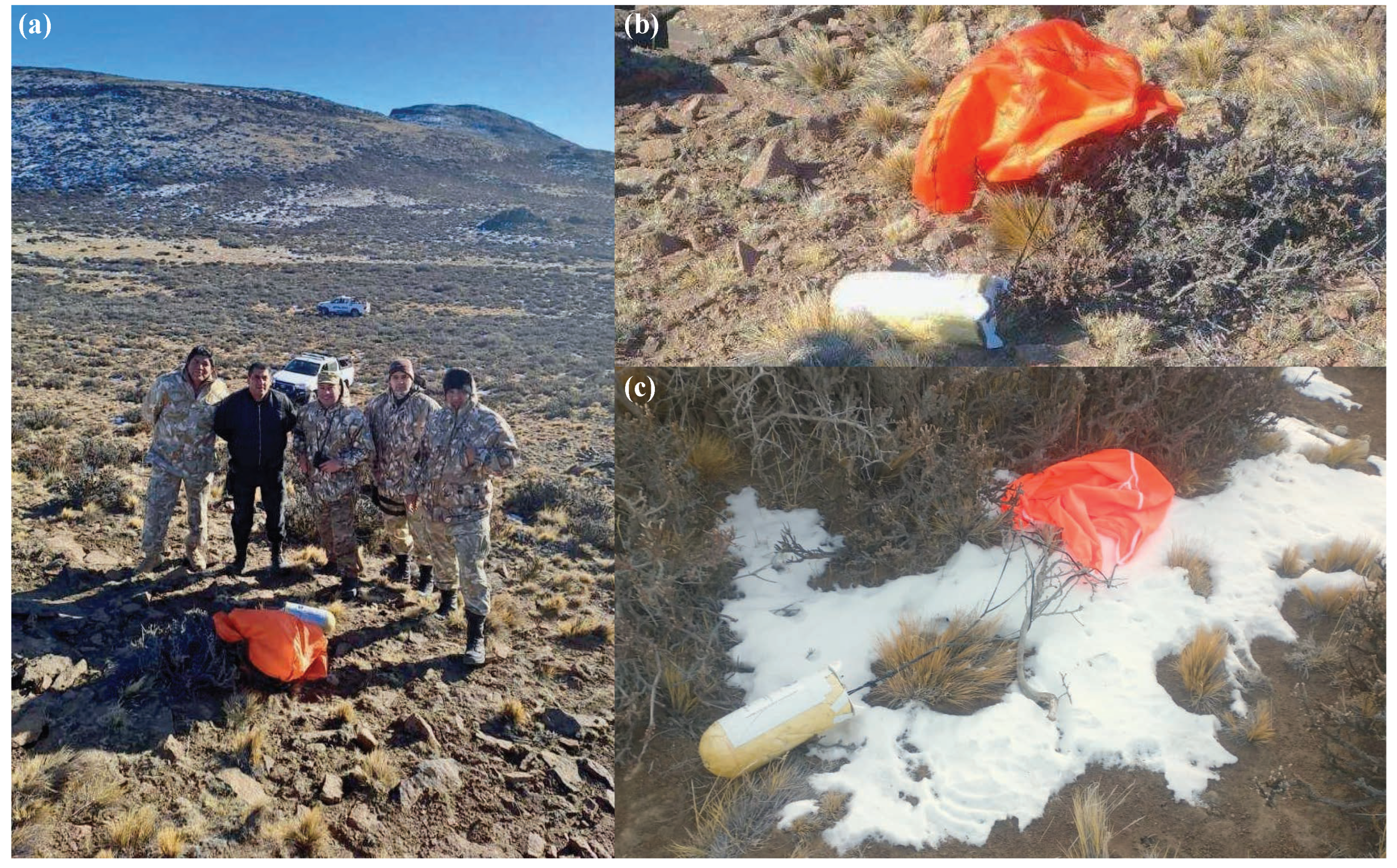
3.4. Successful Recovery

Both drs capsules were found at their reported locations in rolling hills (see Figure 7) by the search and rescue team for the governor’s office of Santa Cruz Province. The bright orange parachutes were visible from a distance, and the beeping was audible. drs1 was found exactly at its reported location, a few hundred metres from a track and ∼24 km from main road 12. drs2 was found a few metres from its reported location, with evidence of cougar prints in the snow. We surmise that foam and parachute nylon are intriguing but not tasty.
We recovered identical copies of all the data from both released drs capsules and later from the unreleased drs and the main data store on superBIT (which also had slightly more telemetry data). However, superBIT had been completely destroyed upon landing, when its parachute failed to detach (perhaps because of similar thermal issues as the drs capsules; analysis is ongoing), and it was dragged for 3 km through similar terrain, leaving a trail of debris. It is, therefore, remarkable luck that superBIT’s solid-state hard drive was later discovered intact. We did not need it because data had already been retrieved from the released drs capsules, but having the original copy enabled us to verify that no data on the sd cards were corrupted.

4. Results

The drs system comprised both hardware and software. Hardware worked reliably throughout the mission in three of the four capsules. They were power cycled every 15 min for 40 days and booted successfully every time. Data were gradually copied to every drs as they were acquired and later (after a mean delay of 20 days at altitude plus two days exposed in Argentina) recovered with no bit errors in 219 GB of files. Curiously, one of the 5920 files accumulated 10 bit errors when being copied from the telescope’s camera data store to the central data store, but none was further corrupted on either the central data store or the drs capsules.
The internal batteries in the drs capsules became very cold at altitude and provided insufficient voltage to power the Iridium transceiver until they warmed up after landing. This meant the true descent trajectories were not recorded, which would have been interesting to compare to our model trajectories. However, the batteries did warm up and worked successfully, even from an exposed, high altitude location on Earth, while covered in snow. The capsules reported their location and were found.
One of the four drs capsules failed to respond after launch. Following the destruction of the telescope to which it remained attached, it is impossible to determine the cause. We speculate that a cable or connector might have been dislodged by the launch shock, but we also note that the drs in question used a brand of sd card that had displayed erratic behaviour during testing. Either way, only 75% hardware reliability calls for additional testing before future use to reduce or improve single points of failure.
The software we developed to predict the trajectory of a drs descending through the Earth’s atmosphere worked very well, with accurate predictions and estimates of uncertainty. This was essential to drop the drs to a safe but accessible landing site. It would also work as backup information to find a drs that failed to respond after release (although the reliability of our hardware other than during launch meant that this was not needed).
Analysis of the astronomical data collected by superBIT and the drs capsules will be presented in forthcoming papers.

5. Discussion

The first use of the drs capsules during a live science mission was a huge success. For a relatively small cost, we insured the scientific returns of superBIT against a loss event that came true: high bandwidth communication links failed, then the telescope was destroyed upon landing. We recommend that future balloon missions consider using this or similar systems. Our hardware design and software are open-source and freely available. Further development is continuing at nasa, with plans to offer a facility-class drs system.
Possible improvements to drs hardware include (a better way to secure) a low-friction connector so it does not become disconnected during launch. The jerk when a drs falls away is sufficient that the right amount of rigidity may be provided by a standard Ethernet socket and plug with the retaining lug removed. Power over Ethernet can remove the need for any separate power cables. A related aspect of this is that securing a drs to the gondola mount currently requires fiddly routing of cables and cable ties inside a cramped case and pulling the ties taut (see Figure 2). More convenient assembly/disassembly will make it easier to perform many more test drops in situ than we achieved.
Thermal management has greatly improved since our test flight in 2019 [6], with the Raspberry Pi operating reliably on demand throughout the mission. The internal batteries got cold, and a (throttled) thermal link from the Pi would have helped them stay ready to work immediately after release. Although our batteries eventually warmed up and worked fine after 40 days cold, we have not tested whether they would also recover as quickly after 100 days cold. It would also have been interesting if the drs stored gnss data (at high frequency) during descent, even though it was too cold to power the Iridium transmitter, so the trajectory could be compared to our prediction. This is not possible in the current design concept, which intentionally has only a low-power microcontroller chip and no flash memory available after release, to maximise battery life in case searching for the drs takes a long time.

Author Contributions

Conceptualization, E.L.S., R.M., L.L., J.D.R., R.S. (Roger Smith) and R.S. (Russell Smith); methodology, A.S.G., A.M.B., P.C., J.E. and R.P.; investigation (drs hardware), J.A., A.H. (Andrew Hunter), N.J., D.K. and S.L.; investigation (superBIT interface), S.J.B., S.W.E., A.A.F., J.W.H., D.H., B.H., E.M.H., M.J., W.C.J., D.L., J.S.-Y.L., T.V.T.L., J.E.M., J.M.N., C.B.N., E.P., S.F.R., A.R., L.J.R., J.S., M.M.S., S.I.T. and G.N.V.; investigation (spb interface), H.F., A.H. (Andrew Hynous), S.R. and R.S. (Robert Salter); funding acquisition, R.M.; supervision, R.M., W.C.J. and C.B.N.; writing, E.L.S. and R.M.; software, E.L.S. and P.C. All authors have read and agreed to the published version of the manuscript.

Funding

This research was funded by the Royal Society (grant RGF/EA/180026), the UK Science and Technology Facilities Council (grant ST/V005766/1), and an Impact Acceleration Award to Durham University. Launch and operational support for the 2023 superBIT flight from Wanaka, New Zealand, was provided by nasa. Funding for the development of superBIT was provided by nasa (grant apra NNX16AF65G), the Canadian Institute for Advanced Research (cifar), the Canadian Natural Science and Engineering Research Council (nserc), and Durham University’s astronomy survey fund. This work was done in part at jpl, run under a contract for nasa by Caltech.

Institutional Review Board Statement

Not applicable.

Informed Consent Statement

Not applicable.

Data Availability Statement

Descent trajectories are available from https://github.com/EllenSirks/pyBalloon. Full instructions to build a drs are available from https://github.com/PaulZC/Data_Recovery_System.

Acknowledgments

We thank the Ministerio de Seguridad de la Provincia Santa Cruz, Argentina, for deploying their search and rescue team to recover the drs capsules. The search was organised by Ministro de Seguridad Sr. Luca Pratti and Subsecretario de Protección Civil, Sr. Diego Farias. Thank you to Juan Perez, German Alejandro Reynoso, Marcelo Alejandro Pemini. and Alan Gabriel Arbe for going into the field—and, sorry for keeping you awake when we accidentally left one drs beeping overnight.

Conflicts of Interest

The authors declare no conflict of interest. The funders had no role in the design of the study; in the collection, analyses, or interpretation of data; in the writing of the manuscript; or in the decision to publish the results.

Abbreviations

The following abbreviations are used in this manuscript:
cpeCo-polyester, a branched version of petg
drsData Recovery System
gfsGlobal Forecast System (weather model)
gnssGlobal Navigation Satellite System, of which gps is a subset
gpsGlobal positioning system
pcbPrinted circuit board
petgGlycol-modified polyethylene terephthalate hard plastic
plaPolylactic acid hard plastic
sbdShort Burst Data (Iridium satellite message)
spbSuper-pressure (closed, helium-filled) balloon
superBITSuper-pressure Balloon-borne Imaging Telescope
tdrssTracking and Data Relay Satellite System

References

  1. Romualdez, L.J.; Benton, S.J.; Clark, P.; Damaren, C.J.; Eifler, T.; Fraisse, A.A.; Galloway, M.N.; Hartley, J.W.; Jones, W.C.; Li, L.; et al. The design and development of a high-resolution visible-to-near-UV telescope for balloon-borne astronomy: SuperBIT. arXiv 2016, arXiv:1608.02502. [Google Scholar]
  2. Karoly, D. (Ed.) Meteorology of the Southern Hemisphere; American Meteorological Society: Boston, MA, USA, 2015. [Google Scholar]
  3. Shaaban, M.M.; Gill, A.S.; McCleary, J.; Massey, R.J.; Benton, S.J.; Brown, A.M.; Damaren, C.J.; Eifler, T.; Fraisse, A.A.; Everett, S.; et al. Weak Lensing in the Blue: A Counter-intuitive Strategy for Stratospheric Observations. AJ 2022, 164, 245. [Google Scholar] [CrossRef]
  4. Clark, P.; Funk, M.; Funk, B.; Funk, T.; Meadows, R.; Brown, A.; Li, L.; Massey, R.; Netterfield, C. An open source toolkit for the tracking, termination and recovery of high altitude balloon flights and payloads. J. Instrum. 2019, 14, P04003. [Google Scholar] [CrossRef]
  5. UN. Committee of Experts on the Transport of Dangerous Goods. Recommendations on the Transport of Dangerous Goods. Manual of Tests and Criteria. Technical Report, United Nations, Geneva. 2019. Available online: https://digitallibrary.un.org/record/3846833 (accessed on 29 October 2023).
  6. Sirks, E.L.; Clark, P.; Massey, R.J.; Benton, S.J.; Brown, A.M.; Damaren, C.J.; Eifler, T.; Fraisse, A.A.; Frenk, C.; Funk, M.; et al. Download by parachute: Retrieval of assets from high altitude balloons. J. Instrum. 2020, 15, P05014. [Google Scholar] [CrossRef]
  7. Gualtieri, R.; Filippini, J.P.; Ade, P.A.R.; Amiri, M.; Benton, S.J.; Bergman, A.S.; Bihary, R.; Bock, J.J.; Bond, J.R.; Bryan, S.A.; et al. SPIDER: CMB Polarimetry from the Edge of Space. J. Low Temp. Phys. 2018, 193, 1112–1121. [Google Scholar] [CrossRef]
  8. Oliver, J.E. Standard atmosphere. In Climatology; Springer US: Boston, MA, USA, 1987; pp. 801–803. [Google Scholar] [CrossRef]
Figure 1. The drs is based around this custom pcb with a Raspberry Pi in the middle. An Ethernet cable is plugged into the bottom right of the Pi and attaches to a zero-extraction force connector at the top right corner of the pcb. Two sd card readers are plugged directly into the Pi, and two are attached to usb extension cables to reduce heat production at the sockets. Servo-operated pincer mechanisms can be seen on the right, with the pincer on the front holding on to the main gondola and the release at the back holding the parachute.
Aerospace 10 00960 g001
Figure 2. The drs capsules hang underneath the payload (here, down is shown to the left). They are prevented from swinging or rotating by a 3D-printed ‘alignment crown’ fixed to their top, which fits inside a mount on the gondola that has an inverted shape.
Aerospace 10 00960 g002
Figure 3. Thermal imaging of the top and bottom of a Raspberry Pi, during testing in a room temperature laboratory. Thermal emission is interpreted as temperature (red, white, green numbers), assuming emissivity e = 0.95 . (a) The main cpu is the hottest component while executing a simple Python script. Nothing is attached to the usb sockets in this image. (b) The underside of a Pi attached to a drs, oriented as in Figure 1. The heat sink and sd card containing the operating system are now cold at the top, but the usb sockets become hot during file transfer to sd cards in small readers mounted in the usb sockets.
Aerospace 10 00960 g003
Figure 4. Self-reported cpu temperature of the Raspberry Pi on each drs during the superBIT mission for drs1 (red), drs2 (blue), and drs5 (green). Temperature principally varied with the 45 diurnal cycles in 40 days (superBIT crossed the international date line 5 times), the length and extent of which varied with superBIT’s speed and latitude. The histogram on the right splits times by positive or negative solar elevation. Insets show temperature variations with increased temporal resolution, including, for illustration, the one occasion when drs1 was left powered on for 30 min. Temperature measurements were only available when a drs was powered on, and horizontal lines merely show the last reported temperature.
Aerospace 10 00960 g004
Figure 5. (a) Close-up of a drs in flight configuration. The closed-cell foam shell surrounding the drs can be seen poking out below a skirt of aluminised Mylar. It is further protected on two sides by sheets of foam insulation also covered by aluminised Mylar. Cables are routed upwards on the mounting frame. (b) superBIT suspended on the launch crane. Four drs capsules can be seen at the bottom, each attached to a corner of the frame holding the solar panels. The blue and white object hanging between them is a ballast hopper. Throughout its mission, the telescope keeps its back (on the right in these photos) oriented towards the Sun.
Aerospace 10 00960 g005
Figure 6. Descent trajectories of drs1 (yellow) and drs2 (red) capsules, which were released over southern Argentina on 25 May 2023. Pins mark the known release and landing positions; everything else was modelled using the pyBalloon software [6]. (a) View from altitude, looking north. Predicted descent trajectories, spanning 62 km horizontally and 32 km vertically. are shown, with vertical lines every 15 s for the first minute, then every 1 min. (b) Location of trajectory within Argentina. (c) Zoomed-in map view, comparing the true landing sites to the predicted 1 σ , 2 σ , and 3 σ uncertainty ellipses. The background image was created with Google Earth, using data from SIO, NOAA, U.S. Navy, NGA, GEBCO, and imagery from Landsat/Copernicus.
Aerospace 10 00960 g006
Figure 7. Landing sites of the drs capsules in Argentina. (a) General terrain and the search and rescue team from the governor’s office of Santa Cruz Province. The bright-orange parachutes of drs1 (b) and drs2 (c) were visible from a distance. The white foam shell and release crown were finally also visible; the foam helped to insulate and waterproof drs2 when it landed on snow.
Aerospace 10 00960 g007
Table 1. Contemporaneous logs from onboard superBIT around the time when two drs capsules were released. Times are UT on 25 May 2023. spb logs #1–4 recorded accurate GPS locations at known times, which we interpolated to the moments of release for drs2 and drs1.
EventTime (UT)Latitude [deg]Longitude [deg]Altitude [m]
spb log #112:29:33 47.685 70.518 32,585
spb log #212:30:37 47.692 70.475 32,488
Release of drs212:31:28 47.696 70.444 32,439
spb log #312:31:40 47.697 70.437 32,428
Release of drs112:31:55 47.699 70.421 32,323
spb log #412:32:44 47.707 70.367 31,981
Disclaimer/Publisher’s Note: The statements, opinions and data contained in all publications are solely those of the individual author(s) and contributor(s) and not of MDPI and/or the editor(s). MDPI and/or the editor(s) disclaim responsibility for any injury to people or property resulting from any ideas, methods, instructions or products referred to in the content.

