Abstract
When a large-scale disaster occurs, each evacuee should move to an appropriate refuge in a speedy and safe manner. Most of the existing studies on the refuge assignment consider the speediness of evacuation and refuge capacity while the safety of evacuation is not taken into account. In this paper, we propose a refuge assignment scheme that considers both the speediness and safety of evacuation under the refuge capacity constraint. We first formulate the refuge assignment problem as a two-step integer linear program (ILP). Since the two-step ILP requires route candidates between evacuees and their possible refuges, we further propose a speedy and reliable route selection scheme as an extension of the existing route selection scheme. Through numerical results using the actual data of Arako district of Nagoya city in Japan, we show that the proposed scheme can improve the average route reliability among evacuees by 13.6% while suppressing the increase of the average route length among evacuees by 7.3%, compared with the distance-based route selection and refuge assignment. In addition, we also reveal that the current refuge capacity is not enough to support speedy and reliable evacuation for the residents.
1. Introduction
When a large-scale disaster, e.g., an earthquake, occurs, each evacuee should move to an appropriate refuge in a speedy and safe manner. Such speedy and reliable evacuation can be achieved by both pre-disaster and post-disaster approaches. The pre-disaster approaches include establishment of refuges [1,2,3,4,5,6], refuge assignment [7,8,9], evacuation planning [10,11,12], and geographical risk analysis [13,14,15,16,17]. From the viewpoint of the refuge assignment, most of the existing studies basically consider the evacuation time and refuge capacity while the safety evacuation is also important.
The pre-disaster approaches can provide us with a global picture of evacuation under predefined assumptions (e.g., refuge locations, geographical population distribution, and road network risk). Since it is difficult to consider all possible disaster situations, the post-disaster approaches are also important to compensate for the mismatch between the assumptions and actual situations.
The post-disaster approaches include evacuation guiding [18,19,20] and signage systems [21,22,23]. In comparison with the pre-disaster approaches, the post-disaster ones can flexibly deal with dynamic environmental changes due to the disaster for supporting the evacuees’ decision making under their high-stressed situation. However, most of the post-disaster approaches implicitly assume that each evacuee selects the nearest refuge for evacuation, which might guide the evacuee to a less reliable route and/or to a filled refuge. In recent years, we can obtain the safety-related information (e.g., geographical risk information) in addition to the capacity-related information (e.g., population distribution and refuge locations and capacities) from governments and some municipalities [13,14,15].
In this paper, we consider the earthquake case study and propose a refuge assignment scheme to achieve speedy and safety evacuations under the refuge capacity constraint. This is a kind of the multi-objective optimization problems, i.e., minimization of route length and maximization of route reliability.
We first formulate the refuge assignment problem as a two-step integer linear program (ILP) under the input of route candidates between evacuees and their possible refuges, which can be solved by the existing solver, CPLEX [24]. As for the route candidates, we also propose a speedy and reliable path selection scheme, which is an extended version of the existing path selection scheme [20] to improve the route reliability.
The proposed scheme can be viewed as either pre-disaster approach or post-disaster one, depending on the knowledge about the locations of evacuees. If the proposed scheme uses the geographical distribution of residents as their initial locations, it can be viewed as pre-disaster refuge assignment for evacuation planning. On the other hand, if it can obtain the actual locations of evacuees under the disaster situations through information and communication technologies (e.g., mobile devices, global positioning systems, and communication networks), it can also achieve post-disaster refuge assignment, which is responsive to the environmental changes.
In this paper, we mainly focus on the pre-disaster refuge assignment under the earthquake case study using actual geographical data (i.e., road blockage probabilities, map of Nagoya city, locations and capacities of refuges, and the distribution of residents), which are provided by the Japanese government and municipality [13,25,26,27].
Through numerical results using the actual data of Arako district of Nagoya city, in Japan, we will show the effectiveness of the proposed refuge assignment scheme in terms of speediness and safety of evacuation under the refuge capacity constraints.
2. Related Work
2.1. Geographical Risk Analysis and Path Selection
In case of evacuation guiding, the simple shortest path may not be enough for the speedy and safety evacuation. Several studies focused on various metrics for the speedy and reliable path selection: traffic congestion [28,29], obstructions related to the presence of debris [30,31], and road vulnerability [13,15,17,32,33]. From the viewpoint of the evacuation speediness, the selfish behavior of evacuees (i.e., trying to move to their refuges as speedy as possible) may cause heavy congestion. To grasp such congestion caused by the selfish behavior, several studies provide pedestrian flow models [28,29]. In [34], Bernardini analyzed the video recording the real earthquake evacuations and proposed a database for earthquake pedestrian evacuation models, which includes the step-by-step evacuation behavior as well as motion quantities (i.e., speed, acceleration, and distance from obstacles). In [35], Liu et al. proposed a path selection method based on the artificial bee colony algorithm to avoid the congestion during the evacuation in building. Kasai et al. proposed a congestion-aware route selection using collected evacuees’ locations through the device to device communication [36]. For simplicity, we focus on the path length as the metric of speediness, but the proposed approach can also be applied to other speediness metrics if applicable.
From the viewpoint of the evacuation safety, Coutinho-Rodrigues et al. proposed a multi-objective location-routing problem using two kinds of paths (i.e., a main path and a backup one), which aims to minimize the distance and risk during evacuations [2]. In this case study, they conducted a case study analysis under the fire-risk assumption where Fire-Risk Index Method [15] is used as a tool for assessing the fire safety in buildings. The fire-risk index is a weighted sum of multiple risk parameters and ranges from 0.0 to 5.0. The high (resp. low) risk index represents the high (resp. low) level of the fire safety. There are several studies on earthquake emergencies in Italy and Japan [20,32,37]. Bernardini et al., considered multiple safety factors for evacuees (e.g., street vulnerability, street blockages probability, and crowding conditions along paths) and proposed a dynamic guidance tool based on Dijkstra’s algorithm with the integrated safety index [37]. Santrelli et al. developed vulnerability indices for a road network under an earthquake [32]. These two studies assumed the possibility of road blockage caused by debris of collapsed buildings, which is evaluated by the road width, the height of buildings along the road, and the vulnerability of buildings [17].
In Japan, a certain municipality (e.g., Nagoya city) also provides the road blockage probability in a similar manner, which represents the probability that the corresponding road segment will be blocked after an occurrence of a certain magnitude of an earthquake. The detailed definition will be given in Appendix A. In [20], Hara et al. proposed a geographical risk analysis-based path selection scheme that provides a speedy and safe route for each evacuee with the help of the road blockage probability.
In this paper, we extend this path selection scheme to improve the path safety and use it to obtain route candidates between evacuees and their possible refuge candidates.
2.2. Evacuation Guiding and Human Interactions
There have been several studies on the indirect/direct evacuation guiding systems: indirect guiding based on signage systems [21,22,23] and direct evacuation guiding systems [18,19,20]. The signage system is one of the building attributions in emergencies as well as ordinary conditions, and provides evacuees with indirect suggestion about evacuation [21,23]. However, Galea et al. demonstrated that the effectiveness of signage systems for evacuation is limited and only 38% of evacuees use the information about evacuation from the signage system [21]. To tackle this problem, the impact of interactions between people and signages on the relationship among the perception, interpretation, and use has been investigated [22,23].
From viewpoint of the direct evacuation guiding, Fujihara and Miwa proposed an evacuation guiding scheme that can work even when the existing communication infrastructures were highly damaged [18]. In this scheme, evacuees manually register the state information of each road (e.g., passable and blocked) to their mobile devices and share it with others through a delay tolerant network [38], which is composed of the mobile devices. Since such manual operations may be difficult under the emergent situations, Komatsu et al. proposed a mobile-edge collaborative automatic evacuation guiding scheme where the evacuees’ mobile devices automatically estimate the road state information through information sharing with their evacuees [19].
In the field of psychology, it has been pointed out that a small number of leaders can lead many evacuees (e.g., follow-direction method and follow-me method) [39]. In [19], the implicit interactions among evacuees through information sharing can be regarded as a kind of such leader-follower communication. Since such post-disaster approaches implicitly build the cooperative relationship caused by human interactions, it can not only improve the evacuation speediness but also contribute to avoiding roads with high risks in an adaptive manner. However, most of studies on the evacuation guiding are the post-disaster approaches and basically adopted the shortest path selection.
To improve the evacuation safety, Hara et al. proposed a geographical risk analysis-based path selection for automatic evacuation guiding scheme, which provided each evacuee with a speedy and safe route by combining the pre-obtained risk information and the collected information during the evacuation [20]. This approach, however, implicitly assumes that each evacuee selects the nearest refuge, which may cause the overflow of the refuge and/or the selection of routes/refuges in high risk regions. In this paper, we propose a refuge assignment scheme that can consider the capacity limitation as well as the speediness and safety of evacuations.
2.3. Refuge Assignment
There have been several studies on the refuge assignment for speedy evacuation under large-scale disasters [7,8,9]. Ng et al. proposed a refuge assignment scheme that considers the balance between the global refuge assignment for minimizing the total evacuation time and the individual selfish refuge selection under emergent situations [7]. Saadatseresht et al. proposed a refuge assignment scheme considering the evacuation route length, population, and refuge capacity, with the help of the multi-objective evolutionary algorithms and the geographical information system [8]. Bayram proposed a refuge assignment scheme such that the route length of each evacuee does not exceed the length of the shortest route plus a certain threshold [9]. These existing studies focus on the speedy evacuation and the refuge capacity while the safety of the evacuation is not taken account. In terms of the evacuation safety, Coutinho-Rodrigues et al. proposed a multi-objective mixed integer linear programming model to minimize the distance and fire risk during evacuations [2,3]. In this paper, we consider the earthquake case study and address the refuge assignment for speedy and safety evacuation under the refuge capacity constraints.
2.4. Multi-Objective Mathematical Programming
As mentioned above, the appropriate refuge assignment must consider the various aspects (i.e., speediness, safety, and refuge capacity), which indicates it is a kind of the multi-objective optimization problem. There have also been several studies on multi-objective optimization, e.g., weighting method [40,41], -constraint method [40,41,42], and AUGMECON [43,44]. Their common goal is to derive the representative subset of the Pareto set, which is the set of Pareto optimal solutions (i.e., solutions that cannot improve one objective function without deteriorating the remaining objective functions). The weighting method transforms the original objective functions into a single objective function, i.e., the weighted sum of them [40,41]. It requires the careful design of the weighting parameters that can consider the relative importance of each objective. -constraint method optimizes the first objective functions under the constraints where each remaining k-th objective function is bounded by a certain threshold [42]. The vector of should be chosen carefully by considering the trade-off among the objectives. The augmented -constraint method (AUGMECON) provides us with the way to determine the range of [43].
In this paper, inspired by -constraint method and AUGMECON, we formulate the refuge assignment as a two-step ILP, where the first step ILP is used to determine the range of parameter and the second-step ILP is formulated based on -constraint method.
3. Capacitated Refuge Assignment for Speedy and Reliable Evacuation
Refuge assignment for evacuees is a kind of combinational optimization problems where we require consideration of multiple important features of evacuation (i.e., speediness, safety, and capacity constraint of refuges).
We first provide notations and criteria for evacuation route, i.e., speediness and reliability, in Section 3.1 and explain the overview of the proposed refuge assignment scheme in Section 3.2. Next, we formulate such refuge assignment as a two-step ILP in Section 3.3. We further propose an algorithm to calculate speedy and reliable route candidates between evacuees and their possible refuges in Section 3.4.
3.1. Preliminaries
Since the refuge assignment is part of the evacuation planning, we focus on the target area for the evacuation planning. In Japan, the unit of the target area is typically a school district and the mayor of municipality must determine designated emergency evacuation site for each disaster type (e.g., earthquake and flood) [45]. denotes the graph representing the internal structure of the target area, where is a set of vertices i.e., intersections or refuges, and is a set of edges i.e., roads. There are D refuges denoted by such that . Suppose that there are evacuees, denoted by , and each evacuee i is initially located at vertex in the target area.
To calculate the refuge assignment, we require the initial locations of the evacuees. The refuge assignment can be regarded as either pre-disaster approach or post-disaster one, according to the knowledge about the initial locations of the evacuees. From the viewpoint of the pre-disaster refuge assignment, the geographical distribution of residents [27] can be used as possible initial locations of evacuees (residents). We can also adopt the time-varying geographical population distribution (e.g., People Flow Data [14]) to consider the initial locations of evacuees under human life cycle (e.g., commuting period in the morning and returning period in the evening). On the other hand, from the viewpoint of the post-disaster refuge assignment, we can collect the actual locations of the evacuees through their mobile devices at the beginning of a disaster if the terrestrial communication infrastructure (e.g., cellular networks and Wi-Fi) is working.
If the terrestrial communication infrastructures are (partly) damaged and unavailable, we can also use device to device (D2D) communication through evacuees’ mobile devices [38,46] and devices with satellite connectivity [47]. Please note that such post-disaster information collection would be affected not only by communication environments but also by the penetration ratio of the proposed scheme as well as evacuees’ privacy settings for their location information. If the post-disaster refuge assignment cannot obtain the actual locations of evacuees, it can also adopt the above-mentioned statistical information as in the pre-disaster one. In what follows, we mainly focus on the pre-disaster refuge assignment where the geographical distribution of residents is used as the initial locations of the evacuees.
The map matching algorithm [48] can find the nearest vertex of the internal graph from a coordinate-based location. is a real-valued function that assigns road blockage probability in closed unit interval to each edge in the risk map. Road blockage probability is an estimated probability that road segment is blocked due to the collapse of building along a road under a certain earthquake [13]. The detailed definition of the road blockage probability is explained in Appendix A.
An evacuation route r can be represented by a vector of roads. We define the length of route r as the sum of the length of each road e in r:
where is the length of road e. In addition, we can also define the route reliability as follows [20]:
which is the probability that all the roads e along the route r are passable under the assumption that the road blockage probabilities along the routes are independent. The route reliability takes a value in the range of and a large (resp. small) value means high (resp. low) reliability. We can obtain the geographical information (e.g., the location of the refuge, the refuge capacity, and the distribution of residents) from the government and the municipalities before the disaster occurs [14,26,27]. Each refuge has a capacity of persons. denotes a set of refuge capacity.
Table 1 summarizes notations used in this paper.

Table 1.
Notation.
3.2. Overview of Proposed Refuge Assignment Scheme
In this subsection, we introduce the overview of the proposed refuge assignment scheme. Figure 1 illustrates the flow chart of conducting the refuge assignment and route candidate. We first calculate the initial locations of evacuees from the geographical distribution of residents [27].
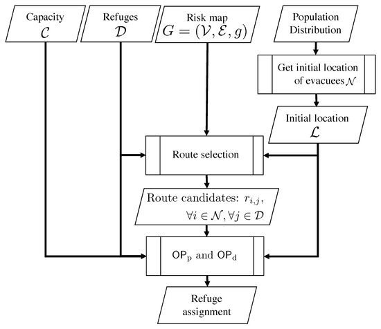
Figure 1.
Flow chart of calculating the refuge assignment and the route candidate.
Since the geographical distribution of residents gives us the number of persons in each sub-region q, , we uniformly allocate evacuees to the vertices in the sub-region q. Let denote the set of sub-regions, and thus .
Considering the fact that some of the residents may stay their home or workplace even under the emergency, we further assume that () ratio of all the residents act as evacuees, denoted by . In such cases, we can regard as .
Next, given risk map , set of refuges , set of refuge capacity , set of evacuees , and initial locations of evacuees , we obtain the route candidates between all evacuees and all refuges using Algorithm 2, which will be described in Section 3.4. Finally, the refuge assignment is obtained by solving ILPs, and/or , which will be described in Section 3.3.
3.3. Two-Step ILP Formulation for Refuge Assignment
As mentioned above, the refuge assignment must be carefully designed by considering the speediness and safety of evacuation under the refuge capacity constraint. This is a kind of multi-objective optimization problems, and thus we tackle this problem in the following two-step ILP.
3.3.1. First Step: Maximization of Average Route Reliability among Evacuees under Refuge Capacity Constraint
Given route candidates between evacuees and their possible refuges as the input data, which will be explained in Section 3.4, we first aim at maximizing the evacuation safety, i.e., the average route reliability among evacuees. This optimization problem can be represented by the following ILP .
The objective function (3) is the maximization of the average road reliability among evacuees, where is the route candidate between evacuee i and refuge j. The calculation of will be described in Section 3.4. is binary decision variable given by (4). If evacuee i is assigned to refuge j, . Otherwise, . The constraint of (5) guarantees that each evacuee i must be allocated to one refuge. Since the overflow evacuees will be required to move to other refuges [49], such overflow conditions are prohibited by (6), which indicates that the number of evacuees assigned to each refuge does not exceed the corresponding capacity.
Since the objective function and all the constraints are linear with the binary decision variables, is ILP, which can be solved by the existing solver, e.g., CPLEX.
3.3.2. Second Step: Minimization of Average Route Length among Evacuees under Refuge Capacity Constraint and Average Route Reliability
By solving the problem , we can obtain the optimal value of the average route reliability . The corresponding refuge assignment, however, may have some room to improve in terms of speedy evacuation. To tackle this trade-off between the speediness and reliability, we further propose a second-step optimization as an ILP , which can be formulated by modifying as follows.
First, the objective function (3) is replaced with
which is the minimization of the average route length among evacuees. In addition to the constraints of , i.e., (4)–(6), adds the following constraint:
The constraint of (8) guarantees a certain level of the average route availability by controlling a parameter , which describes the allowable decrease of average route reliability from the optimal value . If is small (resp. large), the refuge assignment is designed for reliable (speedy) evacuation.
The appropriate setting for will be discussed in Section 4.2. Since the objective function and all the constraints are linear with the binary variables, is also ILP.
3.4. Calculation of Speedy and Reliable Route Candidates between Evacuees and Their Possible Refuges
The solution, i.e., refuge assignment, of the two-step ILP depends on its input parameters, which are the route candidates between evacuees and their possible refuges, i.e., . We propose a speedy and reliable route selection scheme, which is an extended version of the existing route selection scheme [20].
Algorithm 1 presents a function that enumerates at most shortest route candidates between evacuee i and refuge j under the constraint on route length, , and route reliability, . Given road network , evacuee i, refuge j, parameters , and , it first initializes the set of route candidates, , to be empty and the shortest route length to be infinity (line 1). Next, it obtains at most shortest route candidates between evacuee i and refuge j, , by using k function based on Yen’s algorithm [50] (line 2). It also calculates the length of the shortest path in , (line 3). In the next loop of lines 4–8, it extracts speedy and reliable route candidates from . Please note that route candidates in are sorted in ascending order of route length. If the length of route r is longer than that of the shortest path, i.e., , at a certain level, , it stops the loop (lines 5–6). If the reliability of route r is equal or greater than a threshold , it adds r to (line 8). Please note that the existing scheme in [20] does not have this operation, and thus the road reliability is considered in the best effort manner. After the loop, it returns as the speedy and reliable route candidates.
| Algorithm 1: Enumeration of at most shortest route candidates between evacuee i and refuge j under constraint on route length, , and route reliability, . | |
| Require: | |
| Ensure: | |
| 1: , | ▹ Initialization |
| 2: ←k | ▹ Calculation of the -shortest routes |
| 3: | ▹ Calculation of the length of the shortest route |
| 4: for do | |
| 5: if then | ▹ Check on the route length condition |
| 6: break | |
| 7: if then | ▹ Check on the route reliability condition |
| 8: | |
| 9: return | |
The route candidates in change depending on the parameters , , and . and controls the diversity and speediness of route candidates [20]. can be as large as possible under the constraint on the computation overhead. can also be a moderate value by considering both the speedy evacuation and reliable route discovery. On the contrary, the setting of tends to be difficult because the feasible route reliability between evacuee i and refuge j can change depending on the pair of i and j.
Considering these features, we propose a function that calculates the speedy and reliable route candidate between evacuee i and refuge j (Algorithm 2). Given road network , evacuee i, refuge j, and parameters ,, it first initializes to be the maximum value, i.e., one, and to be an empty set (line 1). In the next loop of lines 2–6, it searches for the most reliable route candidate between evacuee i and refuge j under the constraint on and , by decreasing at a certain interval, , e.g., . If it succeeds in finding route candidates using (line 3), it selects the most reliable one as follows (line 5):
Otherwise, If is empty, it continues searching for the route candidates by setting (line 6). As a result, Algorithm 2 provides us with speedy and reliable route candidate between evacuee i and refuge j.
| Algorithm 2: Calculation of speedy and reliable route candidate between evacuee i and refuge j. | |
| Require: | |
| Ensure: | |
| 1: , | ▹ Initialization |
| 2: while do | |
| 3: | ▹ Calculation of the route candidates |
| 4: if then | |
| 5: return according to (9) | ▹ Calculation of the speedy and reliable route candidate |
| 6: | ▹ Update of |
4. Numerical Results
In this section, we evaluate the refuge assignment obtained by solving the two-step ILP, and , using the actual information.
4.1. Evaluation Model
For the evaluation, we select Nagoya city in Japan because it provides us with the risk map where each road is annotated by the road blockage probability [13]. There are 263 school districts, each of which is the unit of evacuation planning [25]. We select Arako district from them by considering the high average road blockage probability. The green area in Figure 2 shows the risk map of Arako district. This map’s internal graph structure is composed of 801 vertices and 1220 edges.
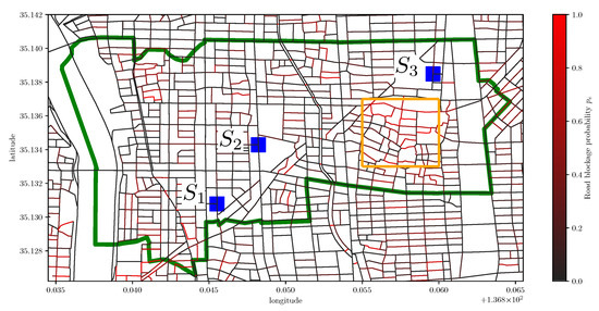
Figure 2.
The map of Arako district covered by the green polygon (), the road blockage probability, and refuges . The orange area contains the roads with high road blockage probabilities.
As for the disaster scenario, Nagoya city provides us with the information of the road blockage probabilities for several classes depending on the degree of damages. In this paper, we use the data of maximum class that consider Nankai megathrust earthquake. Each road in Figure 2 is colored according to the road blockage probability: red (resp. black) means high (resp. low) road blockage probability. The average road blockage probability among all roads is 0.151. The orange area in Figure 2 contains the roads with high road blockage probability, i.e., the average road blockage probability in this area is 0.278. We also show the three actual refuges as blue points in Figure 2, according to [26]. The capacity of each refuge is given as 11,500, 1964, and 8000.
There are 23,156 residents in Arako district [27] and the geographical distribution of residents is shown in Figure 3. We confirm that the three refuges cannot accommodate all the residents, i.e., 21,464 < 23,156.
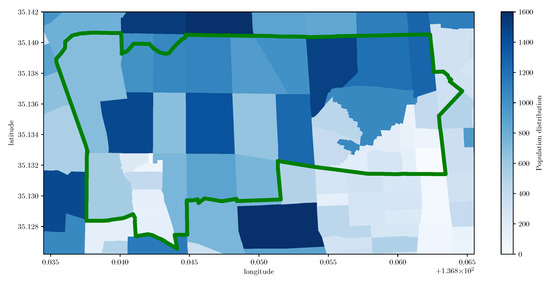
Figure 3.
Geographical distribution of residents [persons] in Arako district covered by the green polygon (2.7 [km] × 1.9 [km]).
In what follows, we set to be 0.7 as an example scenario where some of the residents stay their home or workplace even under the emergency.
For comparison purpose, we use the three schemes depending on the combination of the refuge assignment and the route selection, as shown in Table 2. The distance-based scheme only considers the minimization of the average route length among evacuees, which can be obtained by solving a modified version of ILP where constraint (8) is removed.
Table 2.
Schemes for evaluation.
We use two kinds of criteria. The first one is the average route length, , to evaluate the speediness of the evacuation, which corresponds to the objective function (7). The second one is the average route reliability, , which is related to the objective function (3).
In what follows, we show the average of ten independent numerical results, each of which has different initial locations of evacuees. Through preliminary experiments, we set the parameters for the route selection as follows: 5000, 300, and 0.1.
4.2. Analysis of Trade-Off between Speediness and Safety under Capacity Constraint
In this subsection, we show the performance of the proposed scheme compared with the distance-based scheme under the capacity constraint. Figure 4 illustrates how the allowable deterioration of average route reliability affects the average route length and average route reliability in case of relatively large evacuation demand, i.e., . We first focus on the performance of the proposed scheme. Since small (resp. large) places emphasis on the average route reliability (resp. average route length), we observe that and of the proposed scheme decrease with increase in . We observe that is one of the appropriate parameter settings in terms of both speedy and reliable evacuation. In particular, the proposed scheme can improve by 13.6% with 7.3% increase of , compared with the distance-based scheme. In what follows, we set to be 0.05. In actual cases, the value of may also be affected by other factors, e.g., political judgment.
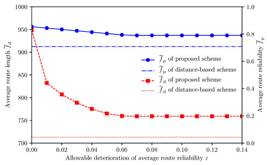
Figure 4.
Impact of on and .
Next, we focus on the obtained refuge assignment. Figure 5 and Figure 6 illustrate the refuge assignment of the distance-based scheme and that of the proposed scheme, respectively. Recall that the orange area in Figure 2 contains the roads with high road blockage probability, i.e., the average road blockage probability in this area is 0.278. In the orange area of Figure 5, some evacuees assigned to are forced to pass through the area with high road blockage probability. Comparing the orange areas in Figure 5 and Figure 6, we confirm that the proposed scheme can reduce such unsafe evacuation by assigning them to .
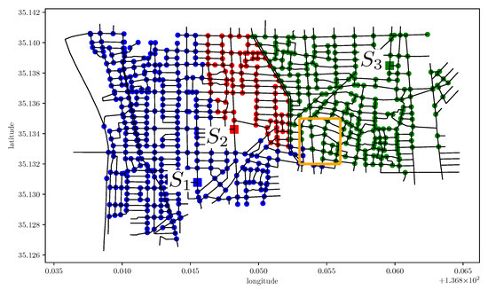
Figure 5.
Refuge assignment of distance-based scheme ().
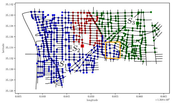
Figure 6.
Refuge assignment of proposed scheme ().
To deeply analyze the characteristics of the proposed scheme, we further show the detailed results per refuge. Figure 7, Figure 8 and Figure 9 illustrate how affects the number of allocated evacuees, , and , per refuge, respectively. We first focus on refuge . We observe that decreases with while keeping the number of allocated evacuees, due to the capacity limit (6). Specifically, we confirm that of can improve by 35.9%, i.e., 392.0 [], by comparing the result of with that of . This result means that evacuees near refuge are assigned to by the relaxation of the constraint (8). On the contrary, we observe that of increases with , which indicates that part of evacuees cannot be assigned to their appropriate refuges, due to the capacity limit (6) in case of . We will describe the details of this result in Section 4.3.
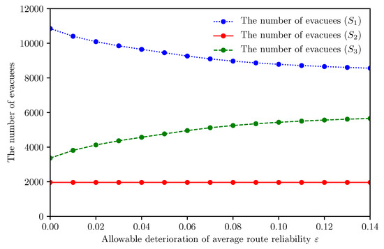
Figure 7.
Relationship between and the number of allocated evacuees per refuge ().
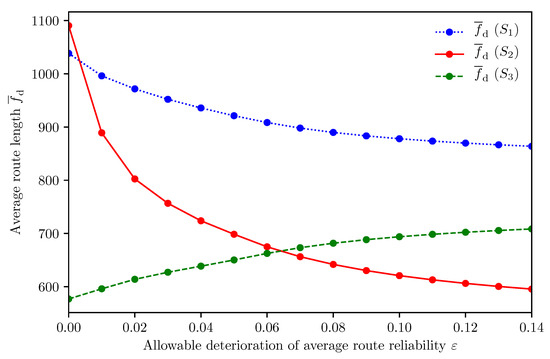
Figure 8.
Relationship between and per refuge ().
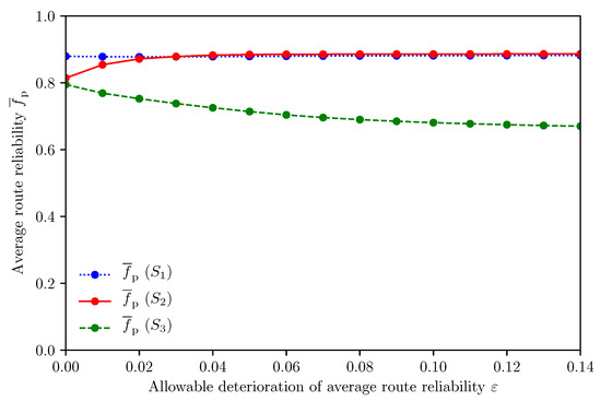
Figure 9.
Relationship between and per refuge ().
Finally, we focus on refuges and . We confirm that of and the number of allocated evacuees of decrease with . This phenomenon can be explained as follows. At first, evacuees distant from are assigned to in case of , to improve the average route reliability. By increasing , these evacuees can be assigned to nearer refuges, and , but most of them can only be assigned to the refuge , due to the limited capacity of . As a result, the number of evacuees allocated to increases with . This forces some of them to pass through the area with high road blockage probability, and thus of decreases with .
4.3. Impact of Capacity Limit on Speedy and Reliable Evacuation
In this subsection, we examine the appropriate design for the refuge capacity by comparing the proposed scheme and that without the capacity constraint, which can be regarded as an ideal case.
Figure 10 presents the refuge assignment of the proposed scheme without the capacity constraint when . Comparing Figure 6 with Figure 10, we first confirm that the proposed scheme without the capacity constraint assigns more evacuees to refuge . This result indicates that the demand for the refuge significantly exceeds the current refuge capacity .
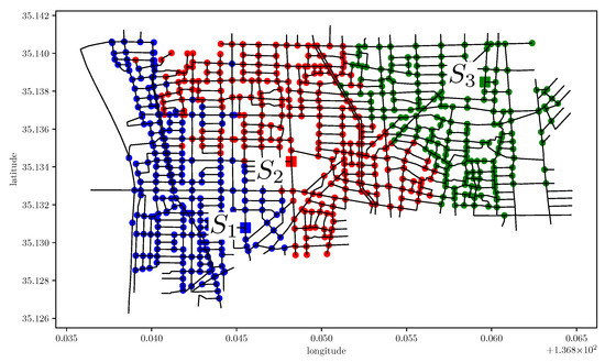
Figure 10.
Refuge assignment of proposed scheme without capacity constraint.
Figure 11 illustrates how the impact of on and changes between the proposed scheme and that without the capacity constraint. Figure 12 shows the corresponding result per refuge. We observe that the proposed scheme increases by 6.5% compared with the proposed scheme without (6) when . This is because the capacity of refuge lacks 4118 of the actual demand as shown in Figure 12. In the proposed scheme, the overflow evacuees tend to be assigned to , which has sufficient capacity and is located at relatively safe region. In Figure 11, we also confirm that the proposed scheme keeps regardless of , compared with the proposed scheme without the capacity constraint.
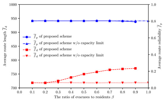
Figure 11.
Impact of on and (proposed scheme vs. proposed scheme without capacity limit).
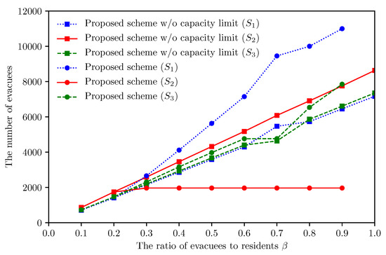
Figure 12.
Impact of on the number of allocated evacuees per refuge (proposed scheme vs. proposed scheme without capacity limit).
These results indicate that the current setting for refuge capacity should be reconsidered especially for refuge . In other words, the proposed scheme can be used to a tool to calculate the required capacity of each refuge for speedy and reliable evacuation.
4.4. Discussion
At the last of this section, we briefly discuss the limit of the proposed scheme from the viewpoint of implementation in real-world context. The refuge assignment based on the proposed scheme should be announced/advertised to evacuees before their evacuations. We expect that the cooperation with the mobile-cloud collaborative automatic evacuation guiding system [19] is one possible way. In this system, the mobile application of an evacuee can automatically estimate the actual road state (i.e., passable or blocked) during the evacuation, with the help of the implicit interactions with its owner. The estimated information will be shared with other mobile devices (evacuees) and cloud through the terrestrial communication networks (e.g., cellular networks and Wi-Fi) and/or D2D communication. These dynamically obtained information can be used to update the refuge assignment.
5. Conclusions
When a large-scale disaster occurs, each evacuee should move to an appropriate refuge in a speedy and safe manner. This can be achieved by the combination of both pre-disaster and post-disaster approaches. In this paper, we have considered an earthquake case study and proposed a refuge assignment scheme that can support speedy and reliable evacuation under the refuge capacity constraint. Given route candidates between evacuees and their possible refuges, we have first formulated the refuge assignment problem as the two-step ILP, which minimizes the average route length while guaranteeing a certain level of the average route reliability under the constraint on the refuge capacity. As for the route candidates, we have further proposed a speedy and reliable route selection scheme that generates the input of the two-step ILP, i.e., route candidates between evacuees and their possible refuges.
Through numerical results using the actual data of Arako district of Nagoya city in Japan, representative results have shown that (1) the proposed scheme can control the balance between the evacuation speediness and reliability under the refuge capacity constraint by adjusting a control parameter and (2) the proposed scheme with the appropriate parameter setting can improve the average route reliability by 13.6% while suppressing the increase of the average route length by 7.3%, compared with the distance-based scheme. In addition, we have also revealed that the proposed scheme can be used as a tool to reconsider the current settings for the refuge capacity. In particular, we have demonstrated that the capacity of a certain refuge lacks 4,118 of the actual demands, which increases the average route length by 6.5%.
In future work, we plan to conduct a comprehensive survey of the potential risks in other districts of Nagoya city.
Author Contributions
Conceptualization, Takanori Hara, Taiki Matsuda, and Masahiro Sasabe; methodology, Takanori Hara, Taiki Matsuda, and Masahiro Sasabe; software, Takanori Hara and Taiki Matsuda; validation, Takanori Hara, Taiki Matsuda, and Masahiro Sasabe; formal analysis, Takanori Hara, Taiki Matsuda, and Masahiro Sasabe; investigation, Takanori Hara, Taiki Matsuda, and Masahiro Sasabe; resources, Takanori Hara, Taiki Matsuda, and Masahiro Sasabe; data curation, Takanori Hara, Taiki Matsuda, and Masahiro Sasabe; writing—original draft preparation, Takanori Hara and Taiki Matsuda; writing—review and editing, Masahiro Sasabe and Shoji Kasahara; visualization, Takanori Hara and Taiki Matsuda; supervision, Shoji Kasahara; project administration, Masahiro Sasabe; funding acquisition, Masahiro Sasabe and Shoji Kasahara. All authors have read and agreed to the published version of the manuscript.
Funding
This research received no external funding.
Acknowledgments
This work was supported in part by JSPS KAKENHI (A) under Grant 19H01103, Japan. The data about road blockage probability were provided by Nagoya city in Japan.
Conflicts of Interest
The authors declare no conflict of interest.
Appendix A. Road Blockage Probability
Nagoya city in Japan has evaluated the regional risks just after the occurrence of a large-scale disaster (i.e., Nankai Trough Earthquake) as the road blockage probability of each road in the region [13]. The road blockage probability is calculated per road according to the three models (i.e., road model, roadside building collapse model, and road blockage model).
The road model consists of the road attributions (i.e., road length and road width) obtained from the city planning basic map. The roadside building collapse model first calculates the probability of total collapse of each building along a road according to the magnitude of an earthquake and building-related parameters (i.e., height, building year, and building type (i.e., wooden or non-wooden)). This model assumes the worst-case scenario where all the buildings on the both roadsides would collapse and the width of road blockage (debris) caused by the building collapse would be the height of the building.
In the road blockage model, the road is considered to be blocked if the difference between the road width and height of collapsed building (i.e., the available road width) is less than , which is the minimum space for walking evacuation. More correctly, this model first divides a road e between two intersections into sections per 20 , which corresponds to the width of the building site, and calculates the blockage probability for each section , , according to the relationship between the road width and the height of the buildings on the section s’s both roadsides (i.e., the height (resp. ) of building on one (resp. another) roadside 1 (resp. 2) of the section s). Without loss of generality, is defined under the assumption of :
where and denote the probability of total collapse of building on one roadside 1 and another roadside 2 of the section s, respectively. Note that and are calculated according to roadside building collapse model.
The road e is considered to be blocked when at least one section is blocked according to (A1). As a result, the road blockage probability can be expressed by
Note that the longer the length of road e, de is, the higher the road blockage probability pe tends to be.
References
- Kongsomsaksakul, S.; Yang, C.; Chen, A. Shelter Location-Allocation Model for Flood Evacuation Planning. J. East. Asia Soc. Transp. Stud. 2005, 6, 4237–4252. [Google Scholar]
- Coutinho-Rodrigues, J.; Tralhão, L.; Alçada-Almeida, L. Solving a Location-Routing Problem with a Multiobjective Approach: The Design of Urban Evacuation Plans. J. Transp. Geogr. 2012, 22, 206–218. [Google Scholar] [CrossRef]
- Coutinho-Rodrigues, J.; Sousa, N.; Natividade-Jesus, E. Design of Evacuation Plans for Densely Urbanised City Centres. In Proceedings of the Institution of Civil Engineers-Municipal Engineer; Thomas Telford Ltd.: London, UK, 2015; Volume 169, pp. 160–172. [Google Scholar]
- Bayram, V.; Tansel, B.Ç.; Yaman, H. Compromising System and User Interests in Shelter Location and Evacuation Planning. Transp. Res. Part B Methodol. 2015, 72, 146–163. [Google Scholar] [CrossRef]
- Kılcı, F.; Kara, B.Y.; Bozkaya, B. Locating Temporary Shelter Areas after an Earthquake: A Case for Turkey. Eur. J. Oper. Res. 2015, 243, 323–332. [Google Scholar] [CrossRef]
- Xu, J.; Yin, X.; Chen, D.; An, J.; Nie, G. Multi-Criteria Location Model of Earthquake Evacuation Shelters to Aid in Urban Planning. Int. J. Disaster Risk Reduct. 2016, 20, 51–62. [Google Scholar] [CrossRef]
- Ng, M.; Park, J.; Waller, S.T. A Hybrid Bilevel Model for the Optimal Shelter Assignment in Emergency Evacuations. Comput. Aided Civ. Infrastruct. Eng. 2010, 25, 547–556. [Google Scholar] [CrossRef]
- Saadatseresht, M.; Mansourian, A.; Taleai, M. Evacuation Planning Using Multiobjective Evolutionary Optimization Approach. Eur. J. Oper. Res. 2009, 198, 305–314. [Google Scholar] [CrossRef]
- Bayram, V. Optimization Models for Large Scale Network Evacuation Planning and Management: A Literature Review. Surv. Oper. Res. Manag. Sci. 2016, 21, 63–84. [Google Scholar] [CrossRef]
- Lu, Q.; George, B.; Shekhar, S. Capacity Constrained Routing Algorithms for Evacuation Planning: A Summary of Results. In International Symposium on Spatial and Temporal Databases; Lecture Notes in Computer Science; Springer: Berlin/Heidelberg, Germany, 2005; pp. 291–307. [Google Scholar]
- Yusoff, M.; Ariffin, J.; Mohamed, A. Optimization Approaches for Macroscopic Emergency Evacuation Planning: A Survey. In Proceedings of the 2008 International Symposium on Information Technology, Kuala Lumpur, Malaysia, 26–28 August 2008; Volume 3, pp. 1–7. [Google Scholar]
- Zheng, Y.J.; Chen, S.Y.; Ling, H.F. Evolutionary Optimization for Disaster Relief Operations: A Survey. Appl. Soft Comput. 2015, 27, 553–566. [Google Scholar] [CrossRef]
- City of Nagoya. Earthquake-Resistance City Development Policy. 2015. Available online: http://www.city.nagoya.jp/jutakutoshi/cmsfiles/contents/0000002/2717/honpen.pdf (accessed on 25 April 2019). (In Japanese).
- Sekimoto, Y.; Shibasaki, R.; Kanasugi, H.; Usui, T.; Shimazaki, Y. PFlow: Reconstructing People Flow Recycling Large-Scale Social Survey Data. IEEE Pervasive Comput. 2011, 10, 27–35. [Google Scholar] [CrossRef]
- Larsson, D. Developing the Structure of a Fire Risk Index Method for Timber-Frame Multistorey Apartment Buildings; Student Report; Lund University: Lund, Sweden, 2000. [Google Scholar]
- Sasabe, M.; Fujii, K.; Kasahara, S. Road Network Risk Analysis Considering People Flow Under Ordinary and Evacuation Situations. Environ. Plan. B Urban Anal. City Sci. 2018, 47, 1–16. [Google Scholar] [CrossRef]
- Italian Technical Commission for Seismic Micro-Zoning. Handbook of Analysis of Emergency Conditions in Urban Scenarios (Manuale per L’analisi della Condizione Limite Dell’emergenza Dell’insediamento Urbano (CLE)); CNR, Dipartimento Sistemi di Produzione: Rome, Italy, 2014. (In Italian)
- Fujihara, A.; Miwa, H. Disaster Evacuation Guidance Using Opportunistic Communication: The Potential for Opportunity-Based Service. In Big Data and Internet of Things: A Roadmap for Smart Environments; Bessis, N., Dobre, C., Eds.; Springer International Publishing: Cham, Switzerland, 2014; Volume 546, pp. 425–446. [Google Scholar]
- Komatsu, N.; Sasabe, M.; Kawahara, J.; Kasahara, S. Automatic Evacuation Guiding Scheme Based on Implicit Interactions between Evacuees and Their Mobile Nodes. GeoInformatica 2018, 22, 127–141. [Google Scholar] [CrossRef]
- Hara, T.; Sasabe, M.; Kasahara, S. Geographical Risk Analysis Based Path Selection for Automatic, Speedy, and Reliable Evacuation Guiding Using Evacuees’ Mobile Devices. J. Ambient. Intell. Humaniz. Comput. 2019, 10, 2291–2300. [Google Scholar] [CrossRef]
- Galea, E.R.; H, X.; Lawrence, P.J. Experimental and Survey Studies on the Effectiveness of Dynamic Signage Systems. Fire Saf. Sci. 2014, 11, 1129–1143. [Google Scholar] [CrossRef]
- Xie, H.; Filippidis, L.; Galea, E.R.; Blackshields, D.; Lawrence, P.J. Experimental Analysis of the Effectiveness of Emergency Signage and Its Implementation in Evacuation Simulation. Fire Mater. 2012, 36, 367–382. [Google Scholar] [CrossRef]
- Zhu, R.; Lin, J.; Becerik-Gerber, B.; Li, N. Human-Building-Emergency Interactions and Their Impact on Emergency Response Performance: A Review of the State of the Art. Saf. Sci. 2020, 127, 104691. [Google Scholar] [CrossRef]
- ILOG. IBM ILOG CPLEX Optimizer. 2019. Available online: https://www.ibm.com/products/ilog-cplex-optimization-studio (accessed on 25 April 2019).
- MILT of Japan. National Land Numerical Information Download Service: School District Data. 2010. Available online: http://nlftp.mlit.go.jp/ksj/gml/datalist/KsjTmplt-A27-v2_1.html (accessed on 25 April 2019). (In Japanese)
- Aichi Prefecture. Aichi Prefecture Regional Disaster Prevention Plan Annex. 2017. Available online: http://www.pref.aichi.jp/bousai/boukei/list-fuzoku.htm (accessed on 25 April 2019). (In Japanese).
- MIC of Japan. e-Stat Portal Site of Official Statistics of Japan. 2008. Available online: https://www.e-stat.go.jp/en (accessed on 25 April 2019).
- Fruin, J. Designing for Pedestrians: A Level of Service Concept; Polytechnic University of Brooklyn: Brooklyn, NY, USA, 1970. [Google Scholar]
- Seyfried, A.; Steffen, B.; Lippert, T. Basics of Modelling the Pedestrian Flow. Phys. A Stat. Mech. Appl. 2006, 368, 232–238. [Google Scholar] [CrossRef]
- Kwan, M.P.; Ransberger, D.M. LiDAR Assisted Emergency Response: Detection of Transport Network Obstructions Caused by Major Disasters. Comput. Environ. Urban Syst. 2010, 34, 179–188. [Google Scholar] [CrossRef]
- Santarelli, S.; Bernardini, G.; Quagliarini, E. Earthquake Building Debris Estimation in Historic City Centres: From Real World Data to Experimental-Based Criteria. Int. J. Disaster Risk Reduct. 2018, 31, 281–291. [Google Scholar] [CrossRef]
- Santarelli, S.; Bernardini, G.; Quagliarini, E.; D’Orazio, M. New Indices for the Existing City-Centers Streets Network Reliability and Availability Assessment in Earthquake Emergency. Int. J. Archit. Herit. 2018, 12, 153–168. [Google Scholar] [CrossRef]
- Quagliarini, E.; Bernardini, G.; Santarelli, S.; Lucesoli, M. Evacuation Paths in Historic City Centres: A Holistic Methodology for Assessing their Seismic Risk. Int. J. Disaster Risk Reduct. 2018, 31, 698–710. [Google Scholar] [CrossRef]
- Bernardini, G.; Quagliarini, E.; D’Orazio, M. Towards Creating a Combined Database for Earthquake Pedestrians’ Evacuation Models. Saf. Sci. 2016, 82, 77–94. [Google Scholar] [CrossRef]
- Liu, H.; Xu, B.; Lu, D.; Zhang, G. A Path Planning Approach for Crowd Evacuation in Buildings Based on Improved Artificial Bee Colony Algorithm. Appl. Soft Comput. 2018, 68, 360–376. [Google Scholar] [CrossRef]
- Kasai, Y.; Sasabe, M.; Kasahara, S. Congestion-Aware Route Selection in Automatic Evacuation Guiding based on Cooperation Between Evacuees and Their Mobile Nodes. EURASIP J. Wirel. Commun. Netw. 2017, 2017, 164. [Google Scholar] [CrossRef][Green Version]
- Bernardini, G.; Santarelli, S.; Quagliarini, E.; D’Orazio, M. Dynamic Guidance Tool for a Safer Earthquake Pedestrian Evacuation in Urban Systems. Comput. Environ. Urban Syst. 2017, 65, 150–161. [Google Scholar] [CrossRef]
- Fall, K. A Delay-Tolerant Network Architecture for Challenged Internets. In Proceedings of the 2003 Conference on Applications, Technologies, Architectures, and Protocols for Computer Communications, Karlsruhe, Germany, 25–29 August 2003; pp. 27–34. [Google Scholar]
- Sugiman, T.; Misumi, J. Development of a New Evacuation Method for Emergencies: Control of Collective Behavior by Emergent Small Groups. J. Appl. Psychol. 1988, 73, 3–10. [Google Scholar] [CrossRef]
- Ehrgott, M. Multicriteria Optimization; Springer Science & Business Media: Berlin, Germany, 2005; Volume 491. [Google Scholar]
- Chankong, V.; Haimes, Y.Y. Multiobjective Decision Making: Theory and Methodology; Courier Dover Publications: Mineola, NY, USA, 2008. [Google Scholar]
- YV, Y.H.; Lasdon, L.S.; Da Wismer, D.A. On a Bicriterion Formulation of the Problems of Integrated System Identification and System Optimization. IEEE Trans. Syst. Man Cybern. 1971, SMC-1, 296–297. [Google Scholar] [CrossRef]
- Mavrotas, G. Effective Implementation of the ε-constraint Method in Multi-Objective Mathematical Programming Problems. Appl. Math. Comput. 2009, 213, 455–465. [Google Scholar] [CrossRef]
- Mavrotas, G.; Florios, K. An Improved Version of the Augmented ε-constraint Method (AUGMECON2) for Finding the Exact Pareto Set in Multi-Objective Integer Programming Problems. Appl. Math. Comput. 2013, 219, 9652–9669. [Google Scholar] [CrossRef]
- The Government of Japan. Disaster Countermeasures Basic Act. 1961. Available online: http://www.japaneselawtranslation.go.jp/law/detail_main?re=02&vm=&id=3092 (accessed on 25 April 2019).
- Ansari, R.I.; Chrysostomou, C.; Hassan, S.A.; Guizani, M.; Mumtaz, S.; Rodriguez, J.; Rodrigues, J.J.P.C. 5G D2D Networks: Techniques, Challenges, and Future Prospects. IEEE Syst. J. 2018, 12, 3970–3984. [Google Scholar] [CrossRef]
- Santos, R.; Mosse, D.; Znati, T.; Comfort, L. Design and Implementation of a Witness Unit for Opportunistic Routing in Tsunami Alert Scenarios. Saf. Sci. 2016, 90, 75–83. [Google Scholar] [CrossRef]
- Quddus, M.A.; Ochieng, W.Y.; Zhao, L.; Noland, R.B. A General Map Matching Algorithm for Transport Telematics Applications. GPS Solut. 2003, 7, 157–167. [Google Scholar] [CrossRef]
- Usman, F.; Murakami, K.; Wicaksono, A.D.; Setiawan, E. Application of Agent-Based Model Simulation for Tsunami Evacuation in Pacitan, Indonesia. MATEC Web Conf. 2017, 97, 01064. [Google Scholar] [CrossRef]
- Yen, J.Y. Finding the K Shortest Loopless Paths in a Network. Manag. Sci. 1971, 17, 712–716. [Google Scholar] [CrossRef]
© 2020 by the authors. Licensee MDPI, Basel, Switzerland. This article is an open access article distributed under the terms and conditions of the Creative Commons Attribution (CC BY) license (http://creativecommons.org/licenses/by/4.0/).