Abstract
Because requirements for establishing spatial data for location-based services (LBS) have increased in demand together with an increase in the number of complex structures, especially in urban areas, research has revisited the limitations of data models in representing space. Though research and corresponding applications continue to explore indoor spaces, their complete and accurate representation remains a challenge. Indoor space presents a hierarchical structure, but, unlike their topological relationships, data models have overlooked this. As subspacing presents a method to express this hierarchy of space, we aimed to develop a subspacing framework for expressing topological and hierarchical relationships at various levels of indoor space. We accomplished this by investigating the hierarchy of indoor space structures and how this relates to implementing a multi-level Node-Relation Structure (NRS) representation of indoor space through subspacing. Furthermore, we formalized these concepts by extending the IndoorGML core model. Then, we demonstrated the potential of the proposed framework through an experiment on sample data by generating corresponding network representations at different levels of detail.
1. Introduction
The proliferation of location-based services (LBS) in the everyday lives of humans, especially in urban areas, has grown in tandem with the increased demand for information in these locations. These LBS applications rely on spatial data that abstract real-world spaces that contain human activities. However, the variety and complexity of spaces pose challenges for occupants, researchers, and application developers. Models representing these spaces have continually attempted to obtain semantic and geometric information as entirely and realistically as possible.
However, the applications of these LBS have increased in indoor spaces such as commercial applications, social networking, and path guidance for disabled individuals. As navigation services have become more crucial in indoor spaces [1], information on spatial relationships has proven to be necessary in the topological analysis of relevant situations. As opposed to earlier proposed models based on geometric primitives, the Node-Relation Structure (NRS) allows for the explicit expression of spaces and their topological relationships through a graph structure [2]. This model is the basis for IndoorGML [3]. It has contributed to the acceleration of studies related to indoor space and LBS, mainly associated with navigation and routing, especially for emergencies. The NRS is a network-based model, and research has proven it to be more efficient for spatial queries [4] due to its simple structure of nodes and edges.
The NRS can portray complex spaces and their corresponding relationships despite their simple form, and applications may implement this model depending on its specific needs. For example, for navigation across floor levels, the nodes may represent each floor level and linking edges may represent connectivity relationships within each building floor level. For more detailed navigation, such as among rooms within a floor level, the node representing a floor is decomposable to a subgraph that portrays the floor layout. Each node represents a room or corridor space. Essentially, this multi-level structure enables multi-scale representations of the internal form of an indoor space.
While the NRS has defined this concept, there are no specifications on developing subnetworks down a node hierarchy. Similarly, apart from defining connectivity between multiple layers of space, IndoorGML does not have a mechanism to represent hierarchical multi-level networks. Furthermore, there are no specifications regarding at which scales individual levels should be constructed and, correspondingly, which aspects and constraints of space must be considered at each.
Consider again the example of a node representing an entire floor in a building-level scale network. The nodes that comprise the network at the next hierarchical level must represent the subspaces within a floor level. Hence, a node at a higher level must be dividable into smaller nodes in a lower-level network. To accurately represent the connections of nodes through edges, one must consider the structure of subspaces. IndoorGML defines this decomposition process as subspacing [3]. It is therefore necessary to generate more detailed network abstractions of indoor space. Thus, the process of subspacing results in the generation of data that better represent spaces and hence reduce inefficiency in representing routes [5].
Furthermore, because various occupants of space have diverse needs and applicable constraints, accurate representations of space at various levels of granularity are essential. Portraying navigation paths using the NRS, while applicable and useable, is more suitable for pedestrian navigation. Figure 1 illustrates various agents that navigate indoor space, including persons who traverse with wheelchairs and self-driving robots.
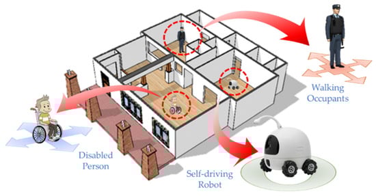
Figure 1.
Various navigating occupants of indoor space.
The NRS framework for modeling indoor navigation focuses on a single locomotion type since it has a single way to represent indoor space. This graph-based portrayal of space is lacking and not applicable to robots or flying objects such as unmanned aerial vehicles (UAVs) [6]. Furthermore, network data may be helpful in the localization of other indoor agents, such as environmental variables. For example, when tracking fire or smoke spread, a granular space subdivision is necessary to precisely pinpoint locations. This representation also allows for the full coverage of an area of interest [7], similar to cellular automata (CA) approaches and base data used in agent-based simulations. Therefore, the subspacing concept is essential in generating network data to fully describe the hierarchy of indoor spaces. More importantly, using multi-level networks can widen the applications for generated data.
The authors of this study aim to propose a subspacing framework for generating multi-level hierarchical topological data for indoor space. Accordingly, we define levels of space hierarchy within a building structure and appropriate network representations for each. We consider various constraints that the subspacing procedure must consider for each level. Through these concepts, we aim to illustrate the hierarchy of indoor spaces, how the subspacing process generates this hierarchy, and how network-based data consequently express these relationships. We formalize our hierarchical framework by presenting an extended IndoorGML core module and implementing sample data as illustrative examples.
Though we propose a framework for generating network data that express topological and hierarchical relationships, we do not focus on the precise geometric representation of indoor space. Using a network-based topology representation employs a cellular rather than Euclidean notion of space. As such, the positioning of the navigation agents, including reference systems and localization techniques, is not within our paper’s scope. Furthermore, rather than the accuracy of each method in generating detailed subspaces, we focus on which subspacing methods are appropriate to generate the desired network at a specific hierarchy level.
We organize the paper as follows. The next section reviews related studies to indoor space representation, topological models, hierarchical models, and subspacing. Then, we discuss the hierarchy of indoor space, how subspacing plays a role in generating data at each hierarchical level, and how the dataset expresses these relationships. In the same section, we propose a framework for generating network data for each hierarchical level and the IndoorGML extension to formalize the hierarchical relationships. Following this section, we demonstrate our proposed framework and hierarchical model using an experiment performed on sample data. The closing section summarizes the study and directions for further studies.
2. Related Literature
As the indoor spaces where human beings are present have become more complex, related studies and developments have accordingly expanded [8]. Location-based services (LBS) require problem-solving and decision-making tools rather than a mere data presentation platform. Hence, these systems must be capable of analysis. Furthermore, providing these services indoors is critical in natural and non-natural disasters [9].
Topological data are essential in performing spatial analysis. Especially in indoor spaces, these aspects are more vital than a user’s location [10]. The relationships between the features that these datasets represent make it possible to execute complex analyses. Hence, these relationships form the backbone of LBS applications, particularly in urban applications, navigation, and route guidance for humans, robots, and other agents [11,12].
Indoor topological data may be representable in several ways. Initial studies on space topology proposed boundary representations and geometric models as analogs for common two-dimensional (2D) topology data [13]. Through primitives, these models represent real-world objects just as they are perceivable by humans [14]. For instance, the 3D Formal Data Structure (FDS) assumes the complete partition of space into points, lines, surfaces, and bodies. These objects have 1:1 correspondences to real-world objects and thus have geometrical information analogous to topology [14]. Following this, further models have been proposed, e.g., the Tetrahedral Network (TEN) [15] and the Simplified Spatial Model (SSM) [16]. These models similarly support spatial queries and visualization through their topological representation. However, this method of expression computationally burdens applications, especially in large or complex indoor structures, due to its complexity. Topological relationships must be calculated from the primitives since they are not explicitly expressed [13,17]. Hence, it is challenging for these models to implement navigation applications [2].
As an alternative to boundary representations, network-based models utilize graphs that focus on the explicit expression of topological relations. The Combinatorial Data Model (CDM) is a network-based model capable of expressing topological relations in 3D. The process of Poincare duality transforms Euclidean space into dual space. In other words, the 3D spaces and their topological relationships are abstracted into nodes and edges, respectively, and they are collectively referred to as the NRS. This model has been the basis of further models that use network representations such as [18,19,20] and the international standard IndoorGML [3].
However, the NRS is a purely logical model that only describes adjacency, connectivity, and hierarchical relationships. Since there are no geometric properties, there is a limitation on the types of functional analysis for these data. Network-based problems such as detailed pathfinding and allocation analyses require a complimentary geometric network model, such as the 3D Geometric Network Model (GNM) [21]. Since geometry influences the layout and structure of an indoor space, it is also a factor in the hierarchical structure of the GNM. More detailed geometric information can effectively produce lower hierarchical network levels. Consider, for example, the floor-level CDM having a single node representing the corridor space: this node must be decomposed into multiple nodes in the GNM based on geometric information of the room arrangement in the corridor. Suppose we have to generate a much lower-level GNM. In that case, each room must be subspaced into smaller units to represent a more detailed network.
The process of subspacing is this subdivision of space into smaller units. This process uses geometric properties to portray precise paths for indoor space, especially in large areas. The detailed network allows for more accurate analysis, such as efficient routing and indoor localization [22]. Hence, a subspacing framework is essential in expressing the details of indoor space through a space decomposition process. Therefore, this process is also vital to completely transforming a Logical NRS such as CDM into a Geometric NRS such as the GNM. Furthermore, it also allows for the generation of much lower-level hierarchical structures that express indoor space in minute scales.
Space subdivision studies have two perspectives. In indoor positioning applications, sensors must be suitably deployed within indoor space, as this affects accuracy, cost, and service range. The use of Thiessen polygons or Voronoi diagrams [23] is a simple way to determine the arrangement of sensors [24], as is using equally sized grids based on sensor coverage [25]. The initial arrangement of these sensors based on the subdivided areas is adjustable based on sensor ranges, such as in the hexagonal divisions resulting from initial triangular lattices [26]. Obstacles within indoor space are also considered in similar methods [27]. These techniques emphasize the use of space subdivision to improve positioning accuracy, not by increasing the number of sensors but by positioning them efficiently. Cost-effective positioning depends on how the sensor positions divide the indoor space.
Research on establishing indoor paths has also used the determination of subspaces through various criteria. Partitions according to related semantic information for present resources and appropriate agents influence partitions of space, e.g., in defining which subspaces are navigable [28] and the classified function of an area to generate complex navigation networks [22]. Various agent types and their corresponding locomotion modes have also been considered, such as walking for pedestrians, wheelchairs for persons with disabilities, and flying for drones [6,29].
Indoor spaces are not isolated systems because space is fundamentally continuous despite being expressed separately across data and applications [30]. However, studies have demonstrated seamless indoor–outdoor navigation in different scenarios and different models of indoor–outdoor space integration [1,31,32]. However, as agents traverse from outdoor to indoor space, the navigation network is uniformly expressed across these demonstrations. Space is inherently hierarchical, especially indoors, meaning spaces can contain smaller spaces within, e.g., a floor-level containing rooms. Hence, networks across this hierarchy have different scales and can be representable at varying levels of detail.
Suppose we take the case of the experimental demonstration in Kwan and Lee (2005), where a route from a fire station until a disaster site up the 42nd floor of another building. The route starts from the outdoor street network to the building exit, then towards a stairwell to go up the floors, and within the destination floor towards the target room. Outdoor navigation occurs in a macro-spatial environment, and indoor navigation occurs at a micro-level. Consequently, in the same example, there are two distinct scale levels within indoor space. However, it is impractical to express all data in the same level of detail since only some parts are relevant for each section of the route.
Previous research on the topological representation of indoor space has considered hierarchical relationships to enrich the analysis. A topological hierarchical structure enables spatial and semantic queries on user paths resulting from the hierarchies formulated from locations and exits instead of distances [33].
Similarly, the hierarchical decomposition of a building allows for the expression of a structure through its floors and individual rooms based on partitions. Though this representation focuses on the bounding objects’ hierarchy and not the spaces themselves, it demonstrates that such structures are advantageous for representing indoor spaces, especially for rendering volumes. An extension of the Maptree [34], a 2D topological embedding of space, uses building information modelling (BIM) to portray similar hierarchical relationships between building components [35].
As part of the built environment, BIM is the standard for indoor space applications leaning towards the architecture, engineering, and construction domain. Especially with the recent initiatives of the Open Geospatial Consortium (OGC) in guiding the efficient management of cities through 3D open spatial data, BIM is an essential component of representing indoor environments [36]. The consortium also released a collaboration with buildingSMART International, the proponent of the BIM standard industry foundation classes (IFCs), to address the integration with other 3D standards such as CityGML and LandInfra [37]. This report acknowledges that hierarchical relationships provide an appropriate method of realistically representing the physical world. More importantly, the representation of hierarchy among components is shared among the standards and offers an opportunity for integration. A recent study confirmed this commonality, and along with the ArcGIS Indoors Information Model (AIIM), Apple’s Indoor Mapping Data Format (IMDF), and OmniClass, emphasized hierarchical relationships among indoor spatial components [38].
Studies have explored the generation of topological data from BIM data, such as IFC, representing indoor space, using its rich geometric and semantic information [39,40]. While it has precise information on the layout and size of the spaces, hierarchical relationships are still missing from the generated data. However, hierarchical information is still an important aspect when using BIM data in indoor navigation. Detailed information on attributes and application rules also aids the path planning of robots using hierarchical topological maps [41]. Hierarchical relationships in BIM features also have been beneficial in indoor localization approaches in the identification of beacon combinations and more specific signal origins [42]. Above all, the 3D nature of BIM is its advantage in overcoming the limitations of 2D geometric data in navigation applications, paving the way for a proposed BIM-oriented navigation model [43]. Still, these models rely on geometric representations of indoor space, and topology must be derived to obtain data to represent spatial relationships essential for indoor navigation. Furthermore, information on the hierarchical relationships between spaces is still missing, since only hierarchy among building components is present in BIM data.
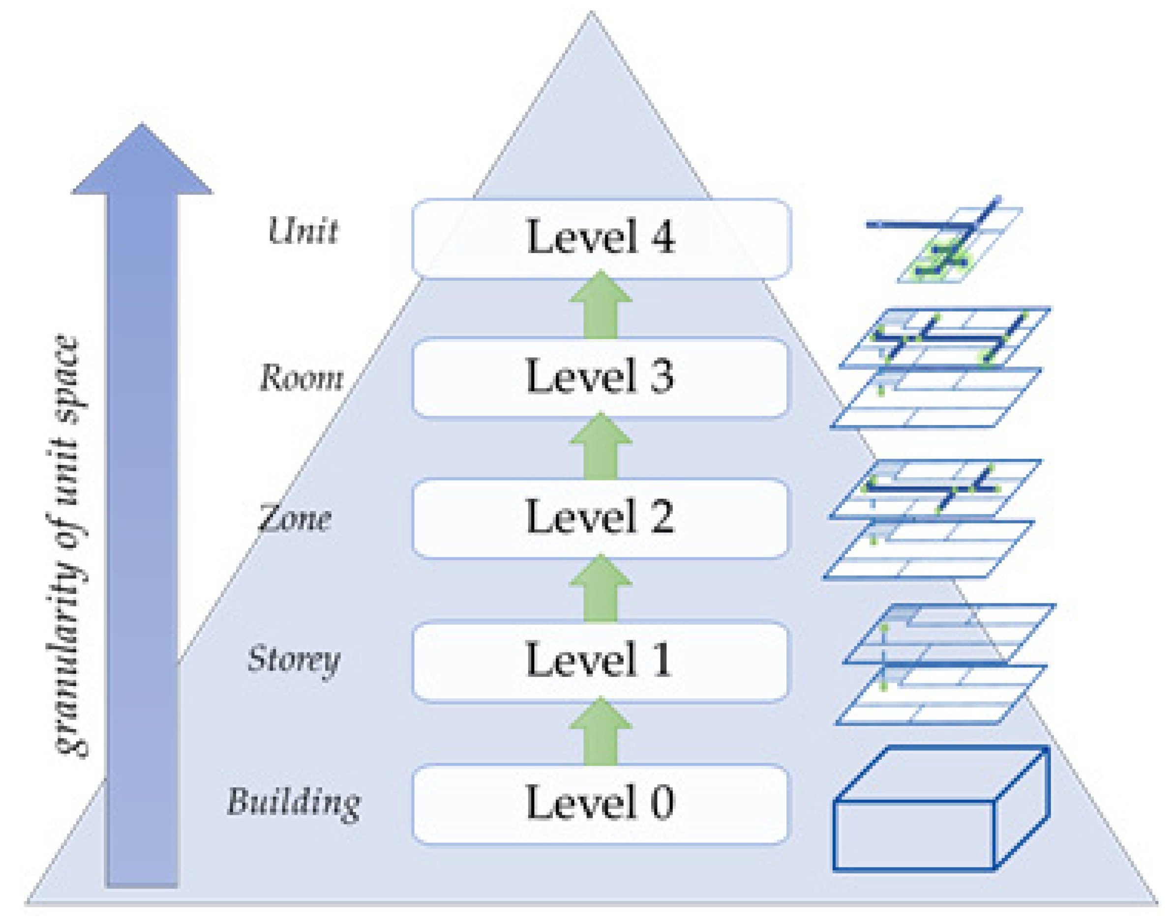
Hierarchically representing space would essentially cover multiple representations of the same space that varies along with the hierarchical levels. This paradigm is closely associated with the concept of the level of detail (LOD). The most well-known instance defined in CityGML [41] is the OGC standard for 3D City Models, which describes five levels with varying semantic information from footprints as LOD 0 up to interior architecture models at LOD 4. In the latest version, OGC dropped LOD 4 [44], and the levels focus more on spatial representations. Published studies have refined this concept to expand LOD 4′s definition in indoor space through BIM [45]. Furthermore, the literature has defined context-aware LODs that may be heterogeneous within a building [46] and sublevels for each of the original levels [47].
For indoor space, studies have also defined LODs based on geometric information, positional accuracy, level of generalization, and semantic content [48,49]. There are also published separate levels for each, such as positional accuracy LOD (PLOD), geometric LOD (GLOD), complete LOD (CLOD), and semantic LOD (SLOD) [50]. The levels’ classification is also present based on applicable service applications [51].
These LOD specifications, for both outdoor and indoor space, focus on geometric and semantic information and still lack definitions that relate to topology and its implications on corresponding navigation applications. Claridades et al. (2021) presented an LOD specification that categorizes indoor network data at increasing scale levels based on applicable space constraints; each level represents the indoor navigable space through a network representation based on the NRS.
3. Framework to Generate a Multi-Level Hierarchical Indoor Navigation Network
This section discusses essential concepts for formulating the framework for generating a multi-level hierarchical network for indoor navigation. First, we discuss the structure of indoor space from a hierarchical perspective to provide context for its relationship to indoor subspacing. Following this, we discuss how network data express these subspaces and their respective spatial relationships to portray topological relationships. Then, we discuss how the data model must express hierarchical relationships and integrate these concepts for a proposed indoor subspacing framework to generate the multi-level network. Finally, we formalize the concepts by extending the IndoorGML core model through a Unified Modeling Language (UML) class diagram.
3.1. Hierarchical Subspacing at Different Space Levels
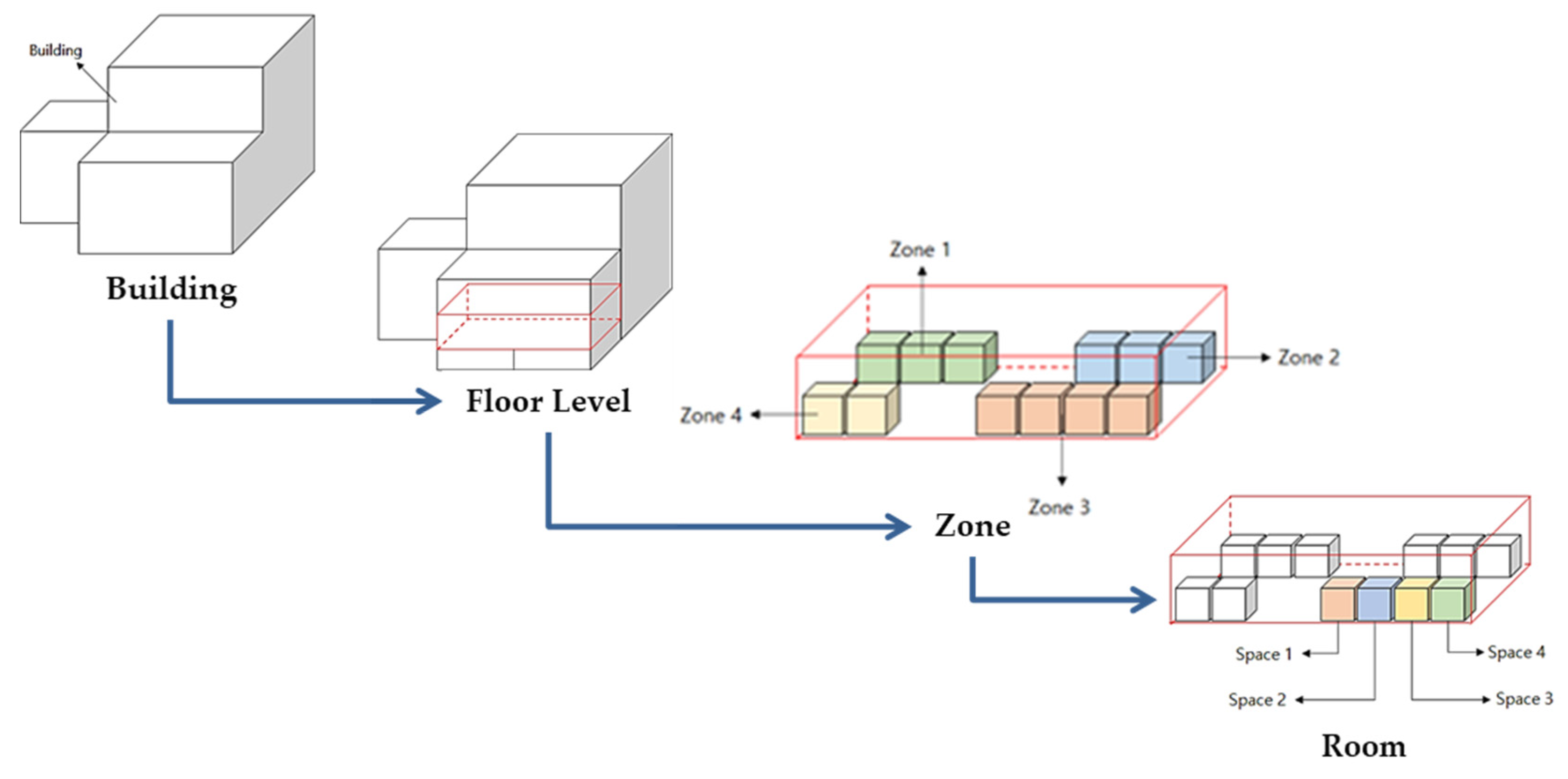
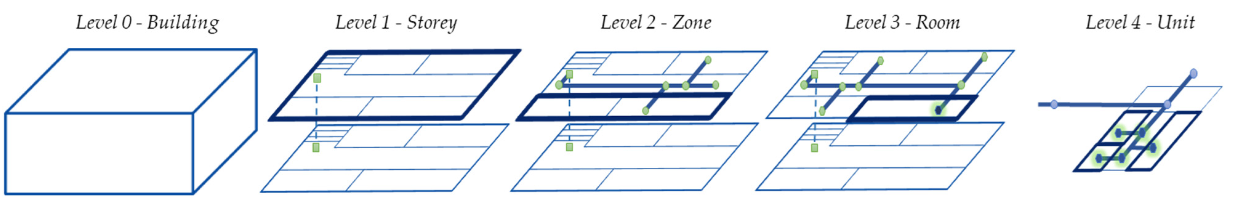
In most data models, such as IFC [52], buildings are logically and physically made up of smaller space components [38]. The subunits of a particular space intuitively describe the indoor space hierarchy, such as that shown in Figure 2. Network datasets representing navigable spaces in these structures are essential for performing location-based services, especially for indoor space. These network datasets represent topological relationships between spaces, such as the adjacency and connectivity of spaces in IndoorGML [3].
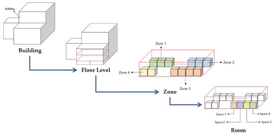
Figure 2.
Hierarchy indoor space levels within a building.
However, current data models lack the depiction of hierarchical relationships, which are essential in fully portraying the detail of spaces at various levels of indoor space. Such relationships allow users to provide more efficient and accurate services, especially in positioning and route guidance. Hence, subspacing is an essential stage in describing hierarchical relationships.
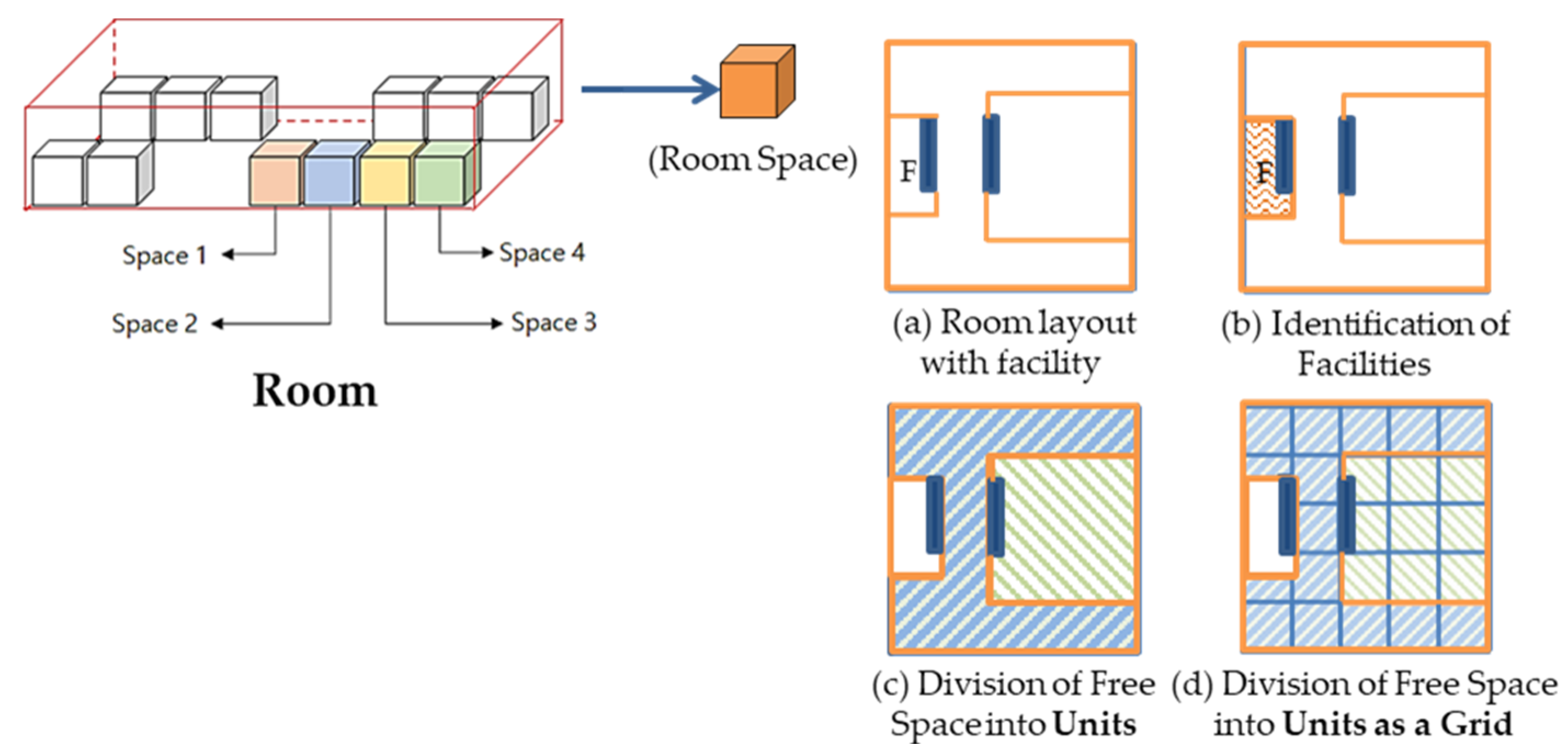
Unlike outdoor space models or indoor models that focus on building components such as BIM, indoor space models are concerned not with architectural components but rather the spaces themselves. Having a different modeling paradigm, indoor space models, such as IndoorGML, consider a cellular notion of space. Non-overlapping cells, not necessarily having the same geometric properties, are defined as the smallest unit of indoor space [3]. In most studies of indoor space, such as the subspacing approaches presented in [6,22,53,54], the rooms are considered the smallest cells or units. However, based on the subspacing framework presented in [55], and the subdivision approaches presented in [5,56], there are smaller elements of space within rooms. Considering a room’s different areas, such as that shown in Figure 3, allows for the room’s division into smaller units to obtain a much more granular subspace.
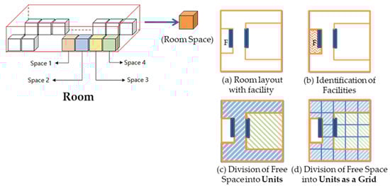
Figure 3.
Subdivision of a room into smaller units.
The need for representing these smaller elements arises in specific applications, especially when we consider obstacles in navigation. As illustrated in Figure 1, we can consider various navigation agents for different use cases when dividing an indoor space. For example, a self-driving robot must avoid obstacles while navigating inside a room. We can identify free spaces by removing the facilities that occupy spaces. Likewise, an agent traveling through a wheelchair faces the same obstacles but may have a different range of movement.
The manner of dividing a room into units may depend on the application. Figure 3c illustrates a logical division with differently-sized units, while Figure 3d shows a complete cellular division. These two examples are at the same hierarchy level, depicting smaller units within a room. Despite the difference in dimensions and subdivision method, each unit is considered an individual cell that shares a common but not overlapping boundary with neighboring cells.
3.2. Expressing Spatial Relationships of Subspaces through Network Data
Along with hierarchy levels, more constraints apply for a particular space, and there is a corresponding applicable space subdivision method. Each of these generates non-overlapping subspaces with sizes appropriate to a particular use case. It is important to note that, by definition, subspacing only generates the subunits of a specific space. A more granular subunit exists for a higher level, which expresses a higher resolution of space fragmentation, which is necessary to model an appropriately detailed navigation. However, these subunits alone are insufficient to facilitate navigation, which requires information on the spatial relationship of spaces within a level. These spatial relationships, such as connectivity, must be expressed as network data.
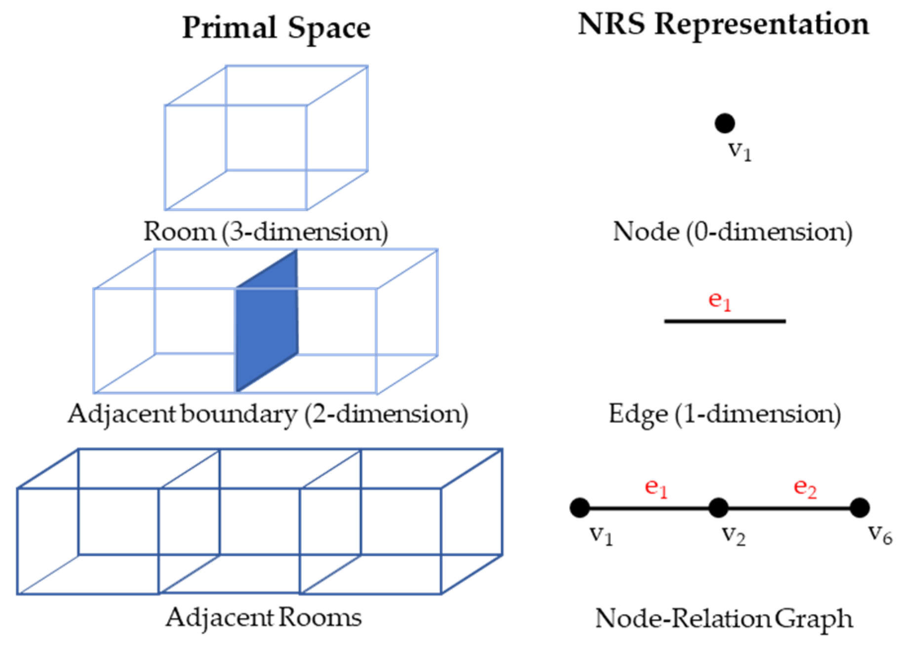
In order to facilitate navigation, the spatial data must express the topological relationships between subspaces. The NRS [2], as discussed in Section 2, is a network representation of indoor spaces composed of nodes that abstract the spaces and edges that portray the topological relationships. It uses the Poincare duality to transform the topological space into dual space to generate an explicit representation of topology in a straightforward manner. In the NRS, a three-dimensional object in the primal space is transformed to zero dimensions in the dual space, converting a 3D room into a node. Likewise, the concept defines a two-dimensional object as one dimension in dual space. Hence, an edge portrays a shared boundary. These objects comprise the node–edge structure of the graph, explicitly representing the topological relationships of the spaces, as shown in Figure 4.
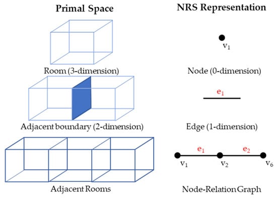
Figure 4.
NRS Representation of 3D indoor space.
While there are numerous ways for spatial data to express topology, the network structure is most suitable for indoor navigation. This advantage is because of its explicitness and simple structure, especially over boundary representation methods [4]. Therefore, one must generate NRS data representing the said relationships through a network structure because it is more appropriate for navigation and portrayal of constraints in indoor space. Figure 5 illustrates the levels of hierarchy representing indoor space at increasing spatial scales, modified from the LOD specification from [55] and adapted to the space hierarchy discussed in the previous section.
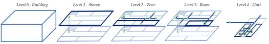
Figure 5.
Levels of detail for representing indoor navigation networks [55].
The levels of detail begin at the fundamental element of spatial hierarchy, specifically an entire un-subspaced building at Level 0. The next level is at Level 1, where each subunit represented as a node in the network varies by height value. Hence, this level contains subunits that each portray a floor level of a building, shown as master_node in the CDM [2]. This level is applicable to the most macro-level analyses of indoor spaces, such as navigation across floors in a building. Additionally shown in the CDM is each master_node, which inherits a subnetwork in Level 1, representing the navigation network across the subunits and hallways at an individual floor level. Level 2 represents a network with nodes representing the zones.
Level 3 contains the subnetworks within these subunits, such as further subdivisions inside rooms, halls, or lobbies. At Level 4, we consider the navigation network characterized by actual free spaces inside the rooms. Notably, together with the recommended constraints and space subdivision methods, Claridades et al. (2021) also suggested corresponding application use cases for each level [55].
Network generation is straightforward for the higher hierarchical levels since space decomposition already enables the connectivity of the generated subspaces. For instance, using the Straight Median Axis Transform (SMAT) in combination with semantic information to create a Level 3 network results in a graph resembling the NRS since the resulting axes are the results of bisecting the original shapes’ edges.
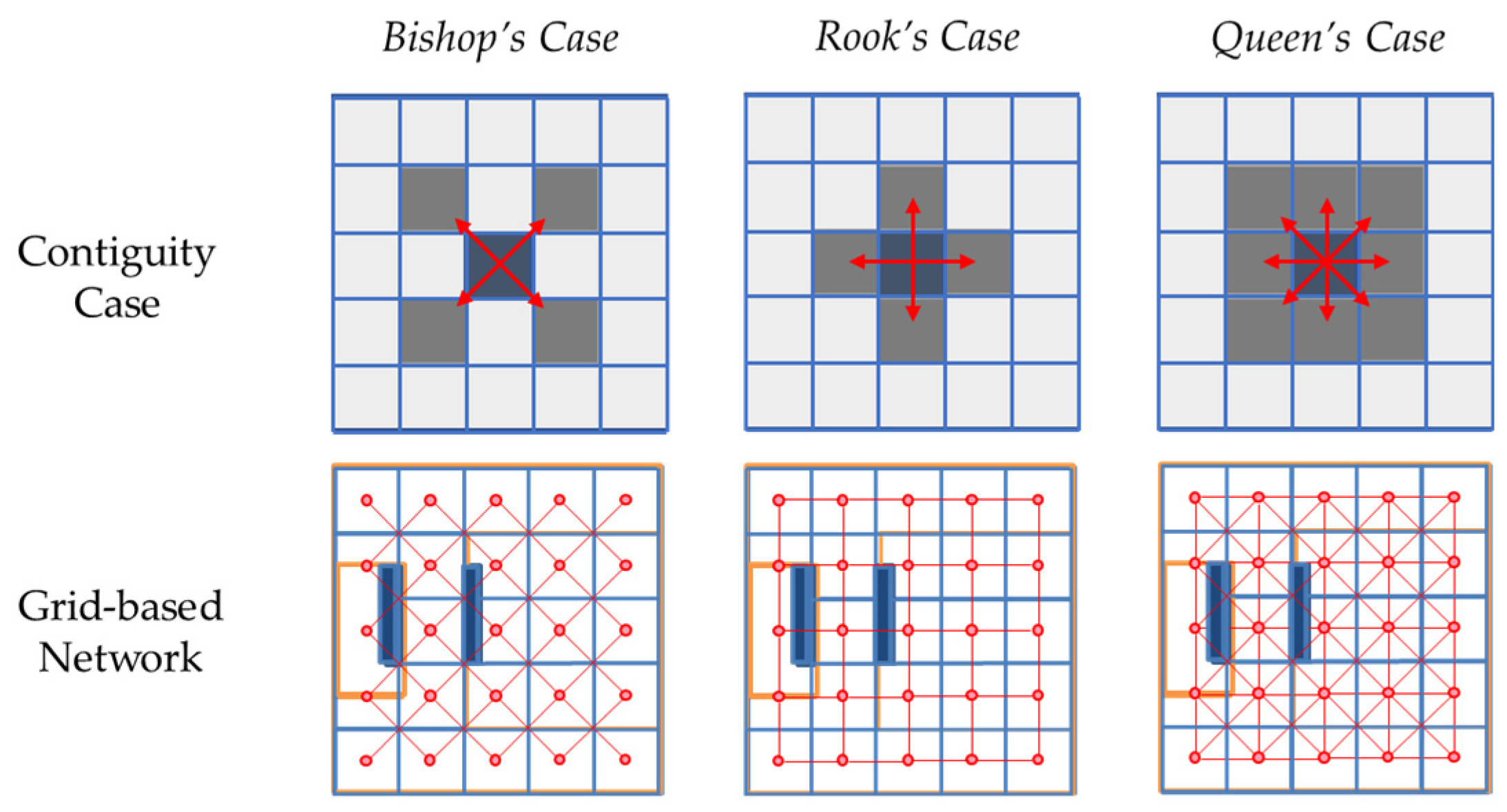
Consequently, for Level 4 networks, using Voronoi diagrams [23] or Delaunay triangulation enables the division of a room into smaller units considering the shape and remaining free spaces. These methods generate edges during the subdivision method, representing the navigation paths. However, for some types of Level 4 networks, we need methods that subdivide the spaces into much smaller units. Such complete subdivision methods produce regular space grids. In these methods, the connectivity relationships are necessary to define where edges must connect the nodes representing the subspaces. Different spatial contiguity cases [57] define the connectivity of a particular grid to its neighbors.
These cases presented in Figure 6 are the basis for how the resulting network data express edges that connect the nodes representing each grid. For example, an occupant navigating through a wheelchair may only move back and forth, so a Rook’s case contiguity may be most applicable. On the other hand, robots with more degrees of freedom in movement may utilize the Queen’s case contiguity. In contrast to voxelization of space, where the representations of subunits are the voxels resulting from the subdivision, this example emphasizes the representation of spatial relationships using network data. Despite being similarly subdivided, the graph representation of the resulting units may differ depending on the considered contiguity.
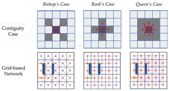
Figure 6.
Contiguity cases for defining connectivity of grids.
3.3. Hierarchical Relationships between Space Levels
Representing spatial data at varying scale levels allows for multiple related depictions of indoor space that can enable efficient data analysis and multi-resolution visualization. The subspacing process is not just a procedure to subdivide indoor space. However, it is also essential to establish the hierarchical relationship between the spaces and the hierarchy levels. This hierarchy is between a subunit of 3D indoor space and its corresponding subunit. From a higher to a lower spatial hierarchy, the dataset represents a more granular perspective of space.
Each node representing a space from a particular coarser level inherits a detailed representation of the same space using a subnetwork composed of lower hierarchical nodes. Hence, though subspacing methods primarily generate subspaces through subdivision, they also establish hierarchical relationships across the levels of representation. Specifically, they create network hierarchy through a node and its inherited subnetwork, as illustrated in Figure 7.
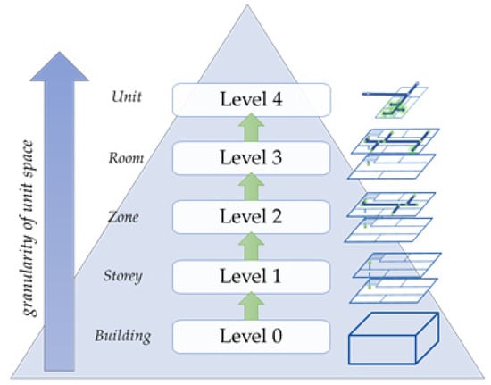
Figure 7.
Spatial hierarchy applied to network LOD.
Existing LOD specifications for outdoor and indoor space depend on geometric and semantic content. These present multiple representations across levels. However, these data are independent and do not support the analysis of the navigability of spaces. In contrast, the LODs we have defined also represent the same space in addition to varying subdivision levels across the levels. As the subdivisions express hierarchy relationships from the subdivided space and its resulting subunits, it also represents the topological relationships.
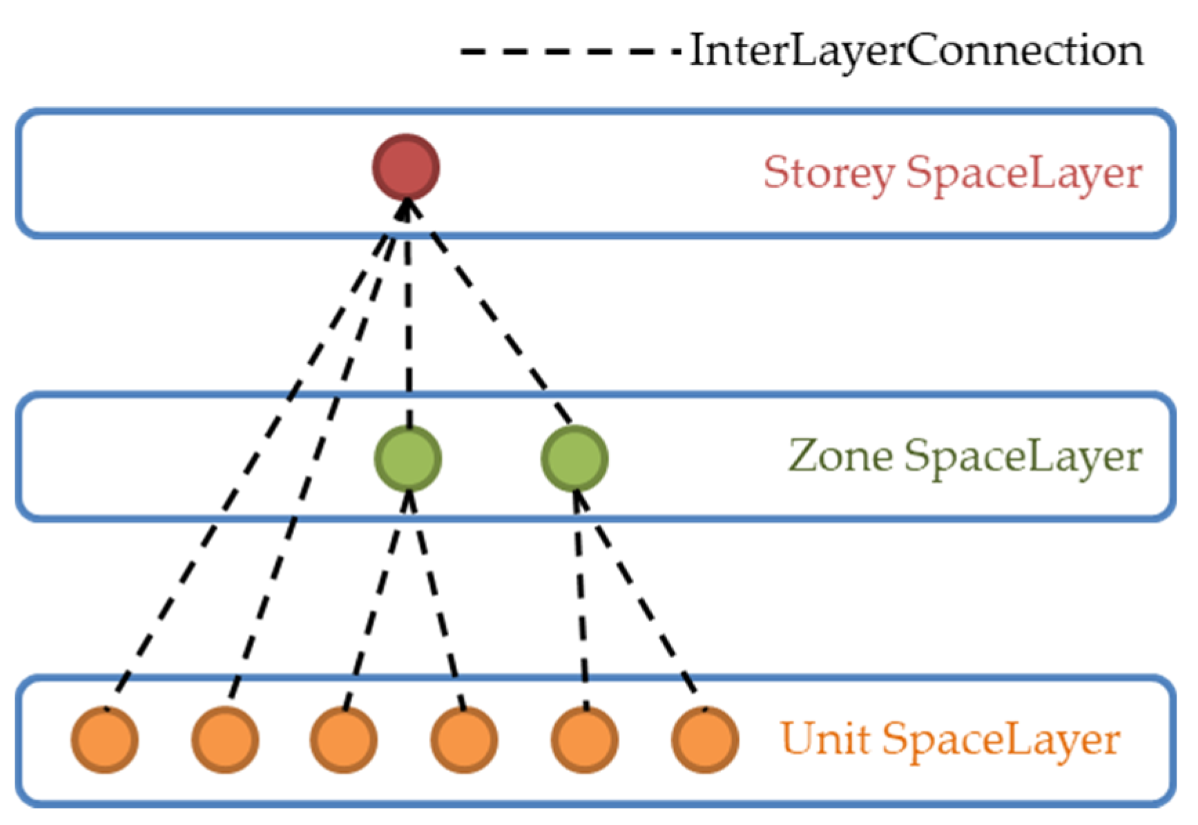
The hierarchical relationship between the levels must be modeled in the data along with adjacency or connectivity relationships, allowing for the simultaneous and efficient implementation of navigation at different scale levels. Similarly, humans move within indoor spaces across building levels, across a corridor within a single level, within a single room on that corridor, and so on. As practical navigation applications require multi-scale data, relationships expressed as hierarchy across levels must also be expressed with network data. Hence, the data model representing the spatial relationships between the subspaces within a level must also represent the hierarchical relationships among the levels. In IndoorGML, SpaceLayer represents an instance of each level connected across through InterLayerConnection, as shown in Figure 8.
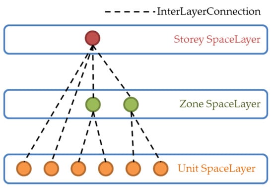
Figure 8.
InterLayerConnection between SpaceLayers representing each hierarchical level.
3.4. Framework for Generating Hierarchical Network-Based Topological Data
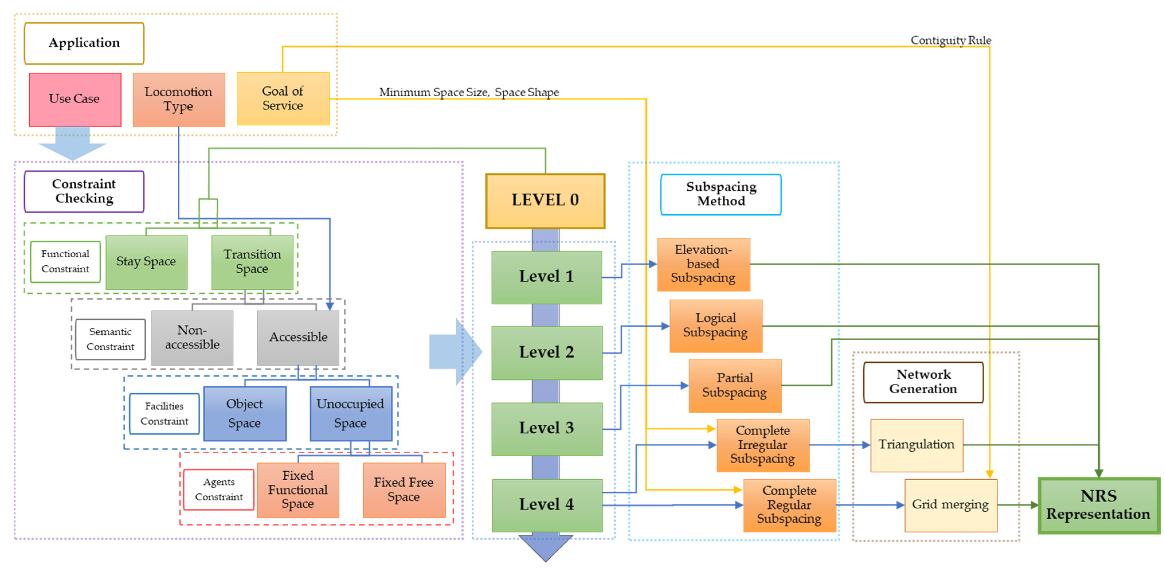
Based on the previously discussed level specifications for corresponding constraints and subspacing methods, together with network generation methods and the concept of hierarchical relationships, we propose a framework for generating network data in Figure 9. The framework illustrates the hierarchical space categorization based on applicable constraints and the corresponding subspacing algorithm for each scale level, as well as recommended network generation methods for the completely subdivided free space.
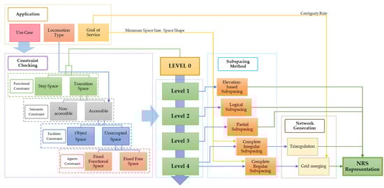
Figure 9.
Framework for generating a multi-level hierarchical indoor navigation network.
In order to determine which level is appropriate in implementing navigation, we should determine appropriate constraints based on the use case. First, we need to examine the function of space. At this stage, each navigable subspace must be differentiated according to function, such as a corridor that facilitates transitions across the space or a room where navigation agents can stay. Similar to the approach by Jung et al. (2015) [54], nodes represent the stay spaces. The transition spaces are further subspaced according to the layout of the rooms to fully reflect actual navigation paths.
Whether a space is accessible or non-accessible for an agent because of the agent’s or the space’s properties is also a factor for subspacing. For example, a space may be non-accessible due to an agent’s size or the space’s time and authorization restrictions. Specifically, only accessible spaces need to be subspaced, as these are the only spaces that can conduct navigation.
Similarly, we must also consider the presence of indoor facilities. Whether movable or immovable [5], these objects occupy spaces and may act as occlusions or obstacles for the agents. These reduce the actual navigable path for the agents despite the space being accessible. Additionally, the agents themselves also constrain navigation. Especially in multi-agent scenarios, other agents act as obstacles that occupy space. Furthermore, how agents use the spaces and facilities also identifies actual free navigable spaces indoors, as demonstrated by [5]. Overall, these constraints influence selecting the appropriate level of hierarchy corresponding to an application (antecedent to identifying a subspacing) and network generation method.
The hierarchical procedure generates a multi-level network representation of the topological relationships of the indoor space. Level 1 networks represent an entire floor level as a node, dividing the building according to the height of each floor level. This network is suitable for navigation across building stories. Logically, the entire floor is divisible into zones for Level 2. For instance, we can characterize one apartment home as a zone in an apartment building. It cannot be considered a single room yet, since there are still rooms inside each apartment. Since a Level 2 hierarchical network inherits from a Level 1 network, we must decompose the master_node representing the zone into a subnetwork describing the layout of the rooms along the building corridor.
Following this, we can represent each room within a zone in the network through subspacing for Level 3. This method entails a partial subdivision method suitable for convex shapes like hallways, such as the SMAT algorithm. As discussed in the previous section, subspacing at this level already results in a network-like structure. Hence, this level is suitable for navigation activities with origin and destinations up to the room level.
Level 4 networks are composed of subnetworks inherited from Level 3 nodes conducive to more detailed navigation paths for areas with more than one possible access. Such spaces may be rooms with multiple doors or large indoor spaces. Hence, we may need to use semantic constraints to identify which spaces need further decomposition to generate Level 4 networks. Since these spaces have various shapes other than corridors, a more general partial space decomposition method generates the subspaces. Hence, methods analogous to Voronoi diagrams [23], as discussed in the previous section, are necessary steps to generate a network. These methods are essentially a more general version for those applied in Level 3 networks, and they also generate network-type data. This level is suitable for navigating halls, theaters, airports, or car parks where more specific routes are necessary. Nevertheless, the layout is not implicit, unlike rooms laid along a corridor.
Consequently, other applications may require different manners of subspacing to generate Level 4 networks. For example, applications may need to consider indoor features to determine navigable free spaces within indoor subunits. We can determine a more detailed navigation path by considering facility constraints by differentiating object spaces from unoccupied spaces. Because the remaining free spaces are more varied in geometry, dividing a space entirely according to the service application context is more practical. A complete subdivision into irregular subspaces provides a detailed network suitable for describing a human navigation path. Since these approaches depend more on space-contained objects than a floor layout, algorithms to subdivide space depend on buffering and thinning algorithms. An example of this is the buffering and thinning approach [38], which requires additional steps to connect a network’s subspaces. This level is suitable for applications that require detailed paths within spaces regardless of size, such as avoiding obstacles, especially for the disabled or those with limited mobility.
Finally, the finest level of detail represented in a Level 4 hierarchy is subspacing through grids. In some applications, we deduct object spaces further from unoccupied spaces [5]. This approach does not constrict agents by a single path across a non-linear space. Therefore, the remaining fixed free space is completely subdivided into regular grids or cells, referred to as tessellation. As discussed in the previous sections, the approach must decide on the contiguity rule on how to connect nodes representing the grids to neighboring nodes through edges. At this level, while considering the service goal, we also consider agent constraints such as size and locomotion type to determine parameters for subdivision.
This subdivision is the approach taken by proprietary software ArcGIS Pro in its Indoors Toolbox to generate indoor networks. Walkable spaces, which refer to spaces free from obstructions and furniture, must be identified to draw a lattice of pathways. The uniform density of pathways depends on the smallest doorway in a facility, the orientation of the lattice depends on a pre-defined travel direction [58]. This manner of subspacing is suitable for navigation activities requiring precise localization, such as agent-based simulations or robot navigation, or describing the spread and dispersion of continuous phenomena such as smoke, fire, and environmental variables.
This proposed framework focuses on generating network data that express topological and hierarchical relationships. While these relationships are essential in navigation, some applications would greatly benefit from combining these with geometric data. Multi-scale geometric models are most suitable in this case, usually generated through parametric and procedural modeling [59]. Parametric modeling employs the application of constraints to generate a more detailed level. Though the works of Mueller [60,61] have focused on applying these paradigms to architectural models of exteriors, they demonstrate that sequential applications of operations produce models with high realism. Studies applying this concept in generating BIM and CityGML models [62,63] have shown promise in quickly generating 3D models, albeit lacking in geometric precision.
3.5. Implementation Using the IndoorGML Core Model
In this section, we formalize the topological relationships described in the NRS using the core model of IndoorGML. The OGC published IndoorGML as the international standard for indoor navigation data models in 2014. The State and Transition classes represent the node and the edges, respectively, in the core model. As previously discussed, subspacing generates the same model and sufficiently distinguishes lower-level networks from higher-level ones. However, the hierarchical structure between a space and its subspaces, i.e., across levels, must be represented by extending presently-defined relationships. Figure 10 shows the implementation of the level of detail and hierarchical relationships through modifying the IndoorGML core model through a UML class diagram.
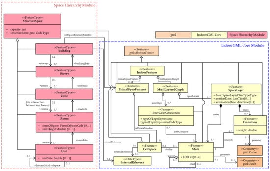
Figure 10.
UML class diagram for IndoorGML extension module for representing hierarchical relationships.
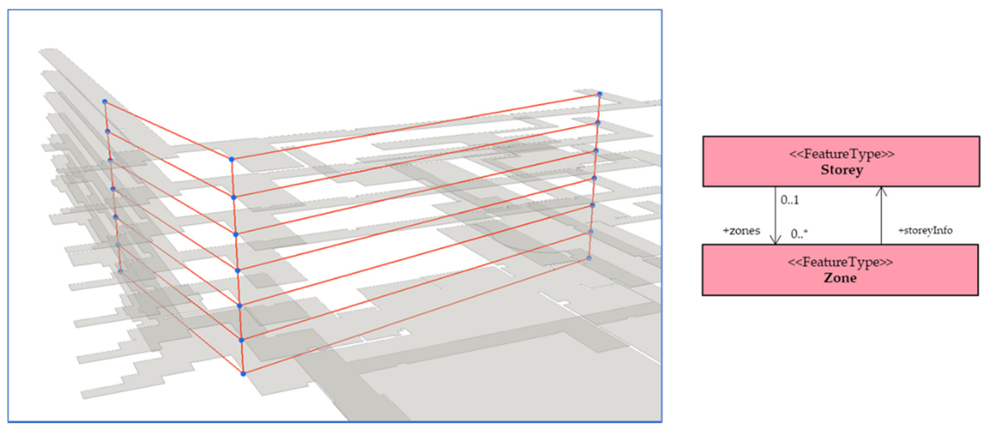
To express the hierarchical relationships between the spaces, we propose a SpaceHierarchy module to support the portrayal of the space hierarchy levels in the UML. We based this module on the core model of IndoorGML, the OGC standard for indoor network-based topological data. The Building class represents the entire built structure and is associated with PrimalSpaceFeatures in IndoorGML core. The Building class is composed of Storey classes through the Storey property. The Storey class, inherited from the StructureSpace class, is made of Zone classes. In turn, these zones contain individual non-overlapping Rooms. These Rooms may be physically or virtually enclosed by boundaries, so the model can specify its form as Open, Closed, Covered, or Semi-Open.
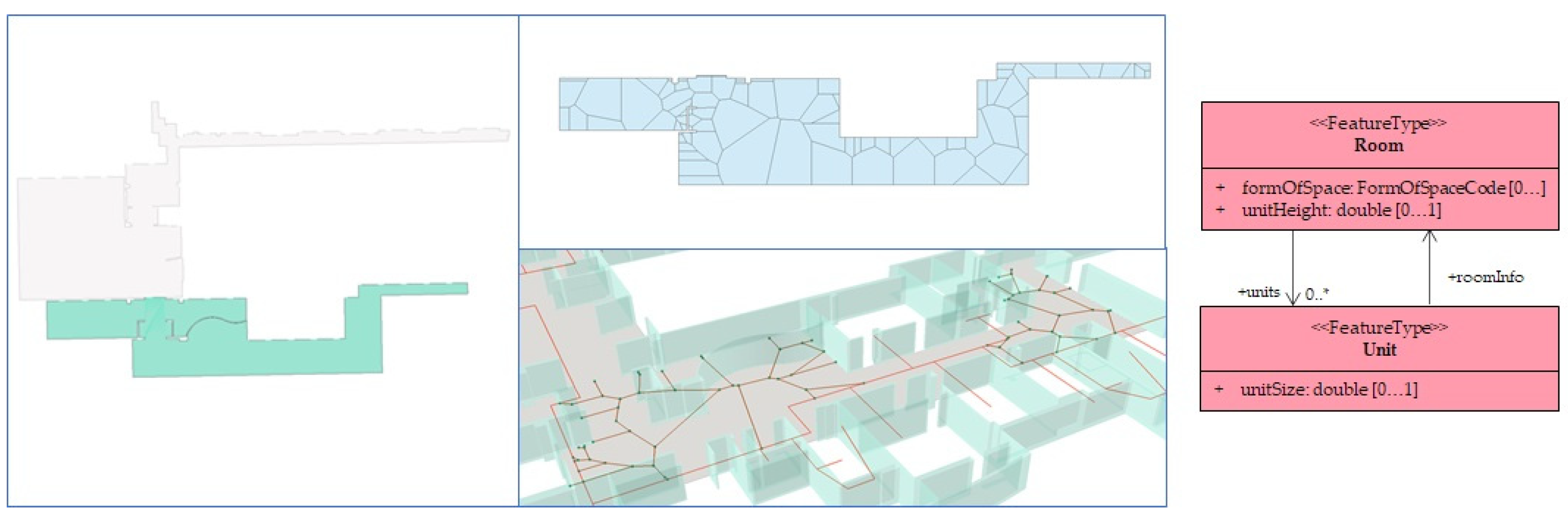
As discussed in the previous sections, we further decompose a Room into smaller spaces represented by the Unit Class. Depending on the application, subdividing the room into units varies in size, so we specify a unitSize property in the diagram. Each unit’s subspaces may also be further subspaced into smaller subspaces, such as a grid. Similarly, these have corresponding hierarchical relationships, as portrayed by the self-association relationship of the Unit Class.
The StructureSpace class inherits from the IndoorGML core CellSpace and contains information on the structure’s capacity and form. Hence, classes inheriting from Structure Space—namely Storey, Zone, Room, and Unit—can be represented as States in the Core Model. Furthermore, we represent these classes as a SpaceLayer. We express their hierarchical relationships in IndoorGML as an InterLayerConnection in the Core model, as shown in Figure 8. This example illustrates hierarchical relationships between the Space Layers for the Storey, Zone, and Unit classes.
We implement the level of detail through expressing a self-aggregation of the State class. Each State instance has a 0~1 parent and a 0~n child, as shown in Figure 10. The multiplicity values indicate that a state may not have a parent class (in Level 1), but it cannot have more than one. Consequently, a State may have no child classes (cannot be subspaced anymore) or may have one or more children. We also express the LOD as an attribute of the State class. As before, the Transition class representing the edges connects two of the State classes representing the nodes at a time.
4. Experimental Implementation
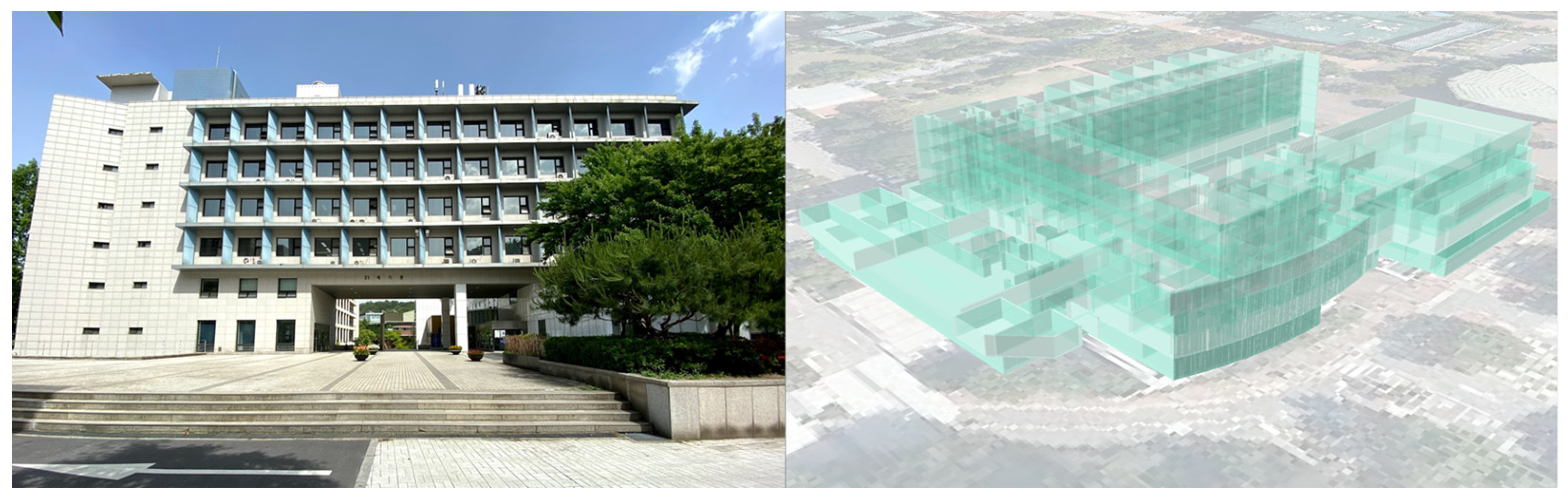
In this section, we identify a use case of a navigation activity across scales of indoor space to demonstrate the potential use of multi-level hierarchical network data. With this implementation, we illustrate the hierarchical subspacing of a building space into the LODs defined in the previous section and the corresponding network data representing the spaces based on the proposed UML. We selected a university campus building as a test site; see Figure 11. We based the geometric data for the experiment on a 3D multi-surface representing the building generated from a 1:5000 topographic map and building floor plans. This building data corresponded to the Level 0 data in the hierarchical levels, represented by the Building class in the UML.

Figure 11.
The study area for the use case implementation.
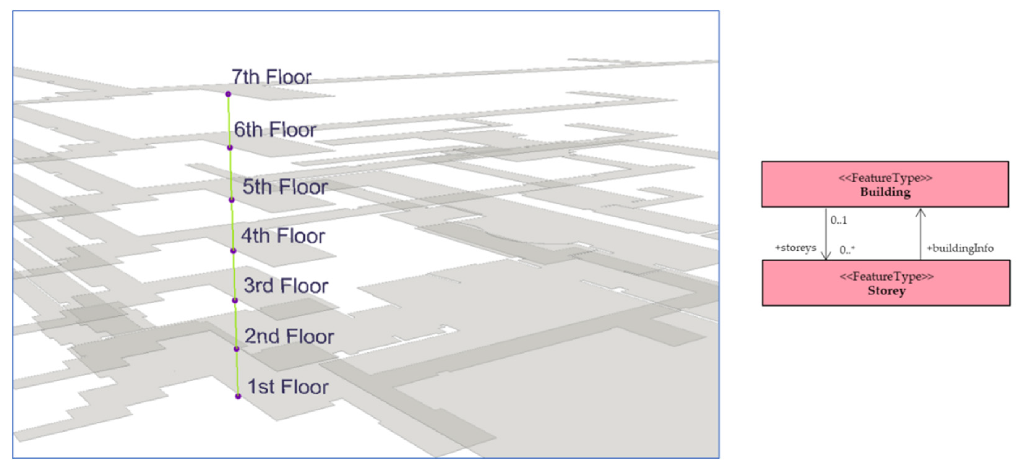
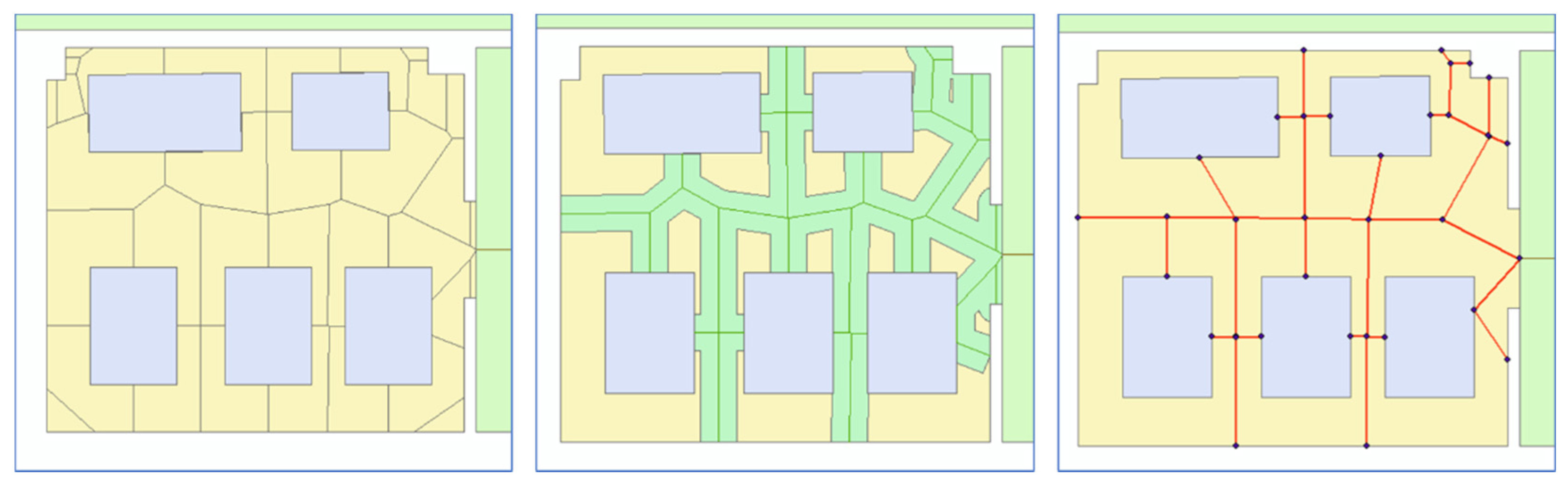
First, we generated a Level 1 network for the building using the process of Poincare duality. An entire floor level was considered a space represented by a node at this level. The connectivity relationships between the floors, expressed through the stairwell, were represented as an edge. Based on the class diagram in Figure 10, each of the nodes in Figure 12 represents an instance of the 1 class, which is associated with the Building class. Figure 12 shows the result for the Level 1 network, which is applicable to floor-to-floor navigation activities, such as when entire floor levels are target destinations [55].
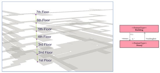
Figure 12.
Level 1 network data representing building floor levels.
Accordingly, the structure of the building in this use case was composed of three major wings. For the Level 2 network, each building wing was considered a Zone, represented by a node. These nodes shown in Figure 13 represent an instance of the Zone class in the UML resulting from the decomposition of each Storey node in Figure 12. This network, shown in Figure 13, is applicable to lower-level navigation activities, such as analyzing the accessibility of indoor areas [19].
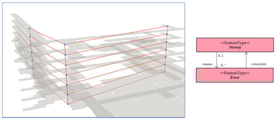
Figure 13.
Level 2 network data representing zones per floor level.
For a Level 3 network, we represented each room in the building as a single node, regardless of which wing contained it. We used an approach based on the Straight Median Axis Transform based on the building floor plan, similar to that used in [21]. Figure 14 shows the resulting network for the second level of the building. Each zone in Figure 13 was further subspaced into smaller spaces, represented by the nodes, which are instances of the Room class from the Space Hierarchy Module. This level of network data appears most commonly in existing studies involving indoor navigation [2,40,64,65,66] since the nodes represent rooms as the basic element of indoor space.
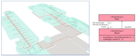
Figure 14.
Level 3 network data representing pathways to rooms inside the building.
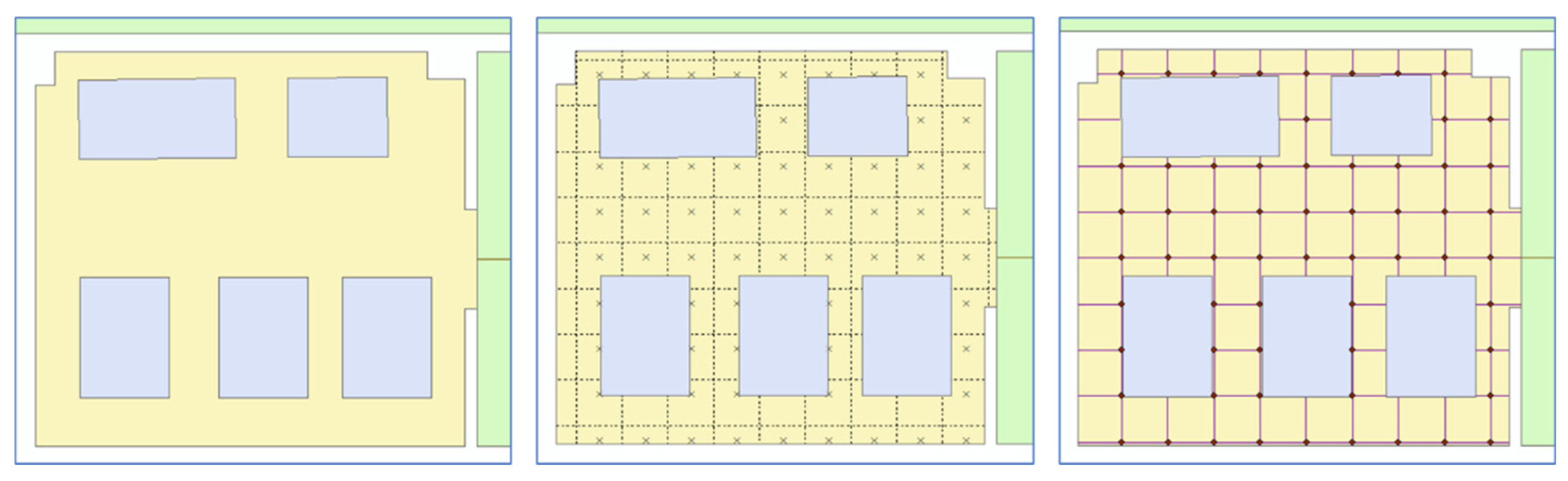
We selected a portion of the second floor for the next level for simplicity and convenience. This decision was made because this portion of the building connects to the rooms in the South Wing. Since it is an open lobby, this portion was represented only as one node in the Level 3 data covering the entire wing. To demonstrate the generation of a Level 4 network, we proceeded with subspacing this area. The selected zone contains the building lobby and a vast part of the corridor, as shown in Figure 15.

Figure 15.
Level 3 network data representing pathways within a lobby.
We implemented a subspacing method for the irregularly-shaped lobby through Voronoi diagrams. We constructed the diagram from points generated from intersections of the polygon centerline and the inward projections of the vertices. Additionally, in Figure 15, the generated edges of the diagram within the building lobby and wide portion of the corridor are visualized along the Level 3 network to illustrate the more complete representation of paths down the lobby. The nodes in the network represent an instance of the Unit class, which resulted from decomposing the lobby-type instance of the Room class.
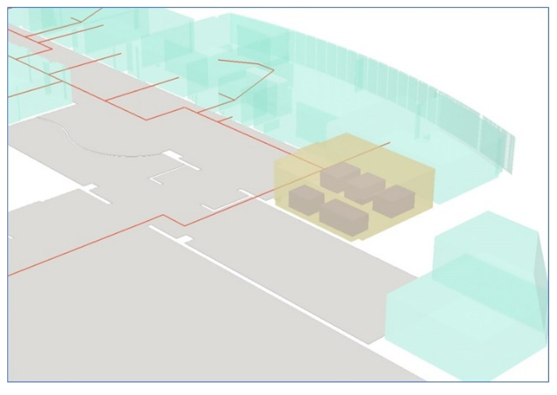
To demonstrate another case of a Level 4 network, we selected a meeting room within the same floor, adjacent to the building lobby in the previous example. As shown in Figure 16, inside the room (in yellow) are furniture (in purple) that may act as obstacles for navigation. Various navigation agents can traverse the free space in the same room, as shown in Figure 1. We illustrate the generation of suitable navigation networks for humans, wheelchair users, and autonomous robots for the following cases.
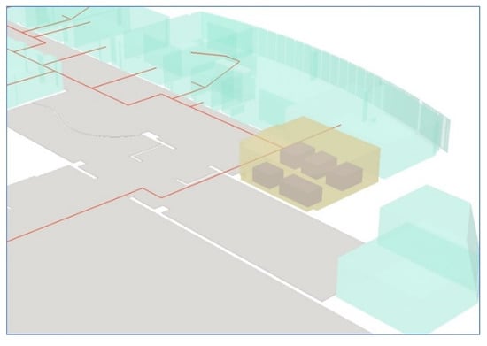
Figure 16.
Selected room for generating a Level 4 network considering facilities.
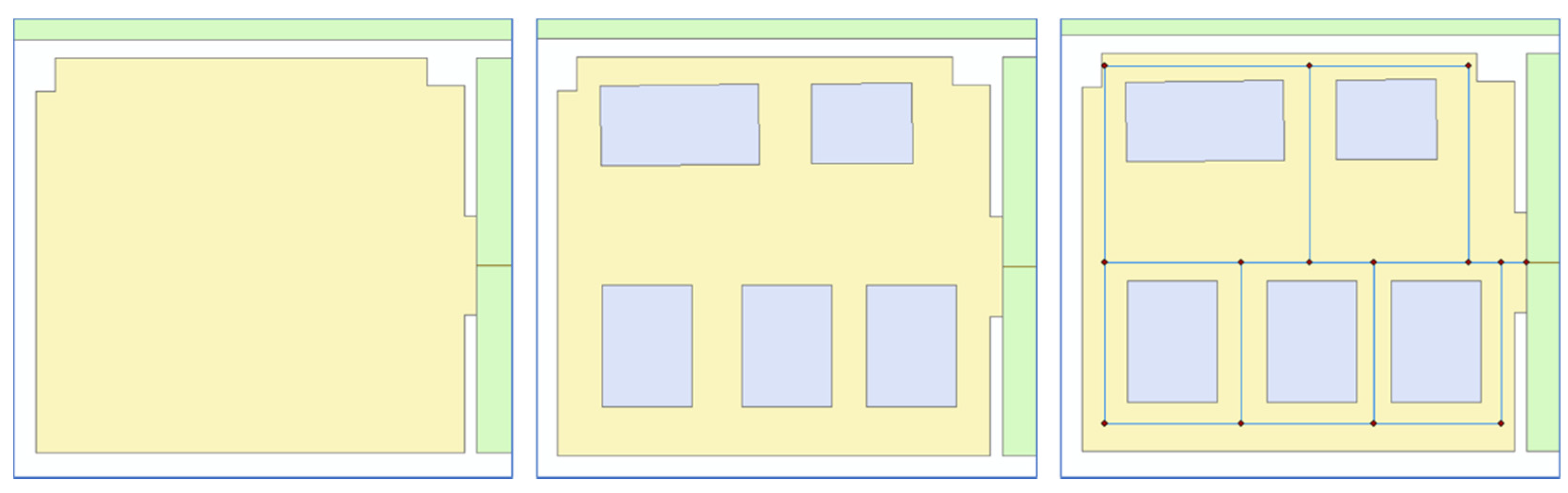
To illustrate the path for human agents inside the room, we used the approach analogous to generating Level 3 networks. Humans require less navigation guidance and precision in indoor space. Hence, subspaces may be larger in size. The furniture arrangement inside the room resembles a hallway type for the remaining free space. Hence, as shown in Figure 17, we generated the network with an approach similar to SMAT.
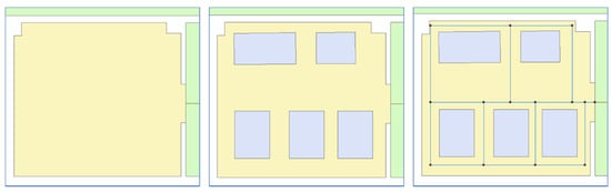
Figure 17.
Generating a Level 4 network for a room with furniture using SMAT.
On the other hand, wheelchair users require more guidance as they navigate in indoor spaces. This condition means that a room must be subspaced to smaller units, leading to a more detailed network than networks intended for human agents. At the same time, furniture also forms obstructions for wheelchair users that must be appropriately considered in subspacing. Following Geraerts’ (2010) approach, the vertices of the remaining footprint were the basis to generate an implicit corridor map (leftmost). From this corridor, we drew a Z-buffer to implement a thinning step to generate the network representing the path within the free space. Figure 18 shows the resulting network in red. We connected the resulting network to the Level 4 network generated for the lobby since they are of the same level.
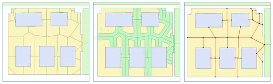
Figure 18.
Generating a Level 4 network for a room using Z-buffering.
More precise localization is necessary for a robot navigating a room, requiring smaller subspaces. We generated a Level 4 network by dividing the same room into grids of equal sizes to demonstrate another case of subspacing a Room into Units. A node represents each grid at its center. Consequently, we generated corresponding edges to form the network, as shown in Figure 19, using Rook’s case contiguity. Likewise, this may be connected to the lobby network because they are similarly Level 4 networks.
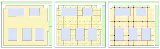
Figure 19.
Generating a Level 4 network for the same room using tessellation.
Figure 20 summarizes the three types of Level 4 networks that may represent the same room space. The node representing the room, and an instance of the Room class in the UML, in the Level 3 network was subspaced differently depending on the navigation agent considered. The nodes of the Level 4 network are instances of the Unit class representing smaller spaces within the rooms. These detailed portrayals of the navigable path of the network enable navigation to extend towards rooms’ interiors, which indoor route applications often overlook. These types of networks also allow for navigation within large spaces and consequently the better projections of trajectories, utilization of functional areas, and consideration of actual human movement [22]. Furthermore, a self-association of the Unit class expresses the three types of Level 4 networks in the model.
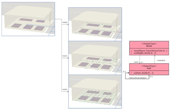
Figure 20.
Self-association relationship of the Unit class to reflect different types of networks for the same Unit space.
In this implementation, we demonstrated an implementation of the proposed subspacing framework using sample data. Using geometric data from a building, we generated network data for each level of detail using specified subspacing and corresponding network generation methods. The generated networks for Level 1, Level 2, Level 3, and Level 4 showed network data containing various levels of detail in describing the spaces in the building. Similarly, we demonstrated the generation of several types of subspacing a Room space by considering possible use cases of a lobby and the interior of a room. The subspacing illustrated for the room showed three different manners of subdividing a space considering indoor facilities and various navigation agents.
5. Conclusions
As requirements for indoor spatial data increase with the growing interest in LBS-related applications, algorithms must address these demands to keep up with the challenges of representing complex and diverse spaces. Especially in navigation applications, topological information is vital for carrying out spatial analysis within 3D indoor space. Numerous studies have addressed the generation of topological network data, such as with the NRS representing the connectivity relationships necessary for indoor network analysis. The NRS is the basis of an established spatial data standard through IndoorGML. However, the literature has been lacking in representing the hierarchical relationship of indoor spaces despite being an inherent and essential property that can better facilitate spatial analysis.
This paper addresses the problem of how to represent the hierarchical characteristics of indoor spaces by proposing a framework to generate multi-level network data to represent spatial relationships. In addition to spatial relationships between spaces within a level, we also defined the hierarchical relationship of the spaces across them. We established spatial hierarchy through a process of subspacing, or the decomposition of indoor space, to generate a subnetwork corresponding to the topological relationships among the resulting subspaces. We identified appropriate constraints that influence subspacing and the subsequent space decomposition algorithms according to each hierarchical level’s target level of information. This level definition, combined with network generation procedures, comprised the proposed framework for generating hierarchical topological indoor space data. The defined hierarchy levels facilitate different depictions of the same space to enable analyses corresponding to degrees of detail.
Furthermore, this study also illustrates an implementation of the hierarchical relationships through a UML class diagram through an extension of the IndoorGML core model. Accordingly, we demonstrated the proposed framework’s potential use by implementing sample data portraying a building. We generated sample network data based on the proposed levels of hierarchy, guided by the proposed IndoorGML extension. Specifically, for Level 4, we demonstrated some possible use cases for subspacing the same space at the same level depending on the application.
This study had some limitations that future research must address. First, the implementation section only focused on the generation of networks. Hence, there is a need to implement actual navigation examples across various levels of network hierarchy. Automating the subspacing process across the levels would greatly benefit from procedural and parametric modeling. These modeling paradigms may aid in producing enhanced 3D geometric models that complement our proposed hierarchical network. Furthermore, forthcoming studies will concentrate on the further evaluation and refining of the proposed subspacing framework, including the identification of more use cases and implementation in other types of indoor spaces.
Author Contributions
Conceptualization, Jiyeong Lee, Hyun-Sang Choi, and Alexis Richard C. Claridades; methodology, Jiyeong Lee and Alexis Richard C. Claridades; software, Alexis Richard C. Claridades; validation, Jiyeong Lee and Alexis Richard C. Claridades; formal analysis, Jiyeong Lee and Alexis Richard C. Claridades; investigation, Alexis Richard C. Claridades; resources, Jiyeong Lee and Alexis Richard C. Claridades; data curation, Jiyeong Lee and Alexis Richard C. Claridades; writing—original draft preparation, Alexis Richard C. Claridades; writing—review and editing, Alexis Richard C. Claridades and Jiyeong Lee; visualization, Alexis Richard C. Claridades and Jiyeong Lee; supervision, Jiyeong Lee and Hyun-Sang Choi; project administration, Jiyeong Lee and Hyun-Sang Choi; funding acquisition, Jiyeong Lee. All authors have read and agreed to the published version of the manuscript.
Funding
This research was supported by a grant (21NSIP-B135746-05) from the National Spatial Information Research Program (NSIP) funded by Ministry of Land, Infrastructure and Transport of Korean government and a grant from the National Research Foundation of Korea (NRF) funded by the Korea government (MSIT) (No. 2021R1A2C1013951).
Institutional Review Board Statement
Not applicable.
Informed Consent Statement
Not applicable.
Data Availability Statement
Not applicable.
Conflicts of Interest
The authors declare no conflict of interest.
References
- Kwan, M.-P.; Lee, J. Emergency response after 9/11: The potential of real-time 3D GIS for quick emergency response in micro-spatial environments. Comput. Environ. Urban Syst. 2005, 29, 93–113. [Google Scholar] [CrossRef]
- Lee, J.; Kwan, M.-P. A combinatorial data model for representing topological relations among 3D geographical features in micro-spatial environments. Int. J. Geogr. Inf. Sci. 2005, 19, 1039–1056. [Google Scholar] [CrossRef]
- OGC (Open Geospatial Consortium). IndoorGML v.1.1. Available online: https://docs.ogc.org/is/19-011r4/19-011r4.html (accessed on 14 November 2021).
- Lee, S.; Lee, J. Validation of Efficient Topological Data Model for 3D Spatial Queries. J. Korea Spat. Inf. Soc. 2011, 19, 93–105. [Google Scholar]
- Diakité, A.A.; Zlatanova, S. Spatial subdivision of complex indoor environments for 3D indoor navigation. Int. J. Geogr. Inf. Sci. 2018, 32, 213–235. [Google Scholar] [CrossRef] [Green Version]
- Khan, A.A.; Kolbe, T.H.; Khan, A.A. Constraints and their role in subspacing for the locomotion types in indoor navigation. In Proceedings of the 2012 International Conference on Indoor Positioning and Indoor Navigation (IPIN), Sydney, Australia, 3–15 November 2012; pp. 1–12. [Google Scholar]
- Li, X.; Claramunt, C.; Ray, C. A grid graph-based model for the analysis of 2D indoor spaces. Comput. Environ. Urban Syst. 2010, 34, 532–540. [Google Scholar] [CrossRef]
- Lee, S.; Lee, J. Efficient Topological Data Models for Spatial Queries in 3D GIS. In Proceedings of the Geospatial Data and Geovisualization: Environment, Security, and Society Special Joint Symposium of ISPRS Commission IV and AutoCarto, The International Society for Photo-grammtery and Remote Sensing (ISPRS), Orlando, FL, USA, 15–19 November 2010. [Google Scholar]
- Lee, J. A Three-Dimensional Navigable Data Model to Support Emergency Response in Microspatial Built-Environments. Ann. Assoc. Am. Geogr. 2007, 97, 512–529. [Google Scholar] [CrossRef]
- Ellul, C.; Haklay, M.; Haklay, M. Requirements for Topology in 3D GIS. Trans. GIS 2006, 10, 157–175. [Google Scholar] [CrossRef]
- Jamali, A.; Abdul Rahman, A.; Boguslawski, P.; Kumar, P.; Gold, C.M. An automated 3D modeling of topological indoor navigation network. GeoJournal 2017, 82, 157–170. [Google Scholar] [CrossRef] [Green Version]
- Worboys, M. Modeling indoor space. In Proceedings of the 3rd ACM SIGSPATIAL International Workshop on Indoor Spatial Awareness-ISA ’11, Chicago, IL, USA, 1 November 2011; pp. 1–6. [Google Scholar]
- Zlatanova, S.; Stoter, J.E.; Isikdag, U. Standards for Exchange and Storage of 3D Information: Challenges and Opportunities for Emergency Response. In Proceedings of the 4th International Conference on Cartography & GIS, Albena, Bulgaria, 18–22 June 2012; Volume 2, pp. 17–28. [Google Scholar]
- Molenaar, M. A Topology for 3D Vector Maps. ITC J. 1992, 1, 25–33. [Google Scholar]
- Zlatanova, S.; Rahman, A.A.; Shi, W. Topological models and frameworks for 3D spatial objects. Comput. Geosci. 2004, 30, 419–428. [Google Scholar] [CrossRef]
- Zlatanova, S. 3D GIS for Urban Development. Ph.D. Thesis, International Institute for Aerospace Survey and Earth Sciences (ITC), ITC Dissertation Series No. 69. Enschede, The Netherlands, 2000. ISBN 9061641780. [Google Scholar]
- Zlatanova, S.; Rahman, A.A.; Pilouk, M. 3D GIS: Current Status and Perspectives. Int. Arch. Photogramm. Remote Sens. Spat. Inf. Sci.-ISPRS Arch. 2002, 34, 66–71. [Google Scholar]
- Smith, J.M. State-dependent queueing models in emergency evacuation networks. Transp. Res. Part B Methodol. 1991, 25, 373–389. [Google Scholar] [CrossRef]
- Dao, T.H.D.; Thill, J.-C. Three-dimensional indoor network accessibility auditing for floor plan design. Trans. GIS 2018, 22, 288–310. [Google Scholar] [CrossRef]
- Choi, J.W.; Kwon, D.Y.; Hwang, J.E.; Lertlakkhanakul, J. Real-time management of spatial information of design: A space-based floor plan representation of buildings. Autom. Constr. 2007, 16, 449–459. [Google Scholar] [CrossRef]
- Lee, J. A Spatial Access-Oriented Implementation of a 3-D GIS Topological Data Model for Urban Entities. GeoInformatica 2004, 8, 237–264. [Google Scholar] [CrossRef]
- Krūminaitė, M.; Zlatanova, S. Indoor space subdivision for indoor navigation. In Proceedings of the Sixth ACM SIGSPATIAL International Workshop on Indoor Spatial Awareness-ISA ’14, Dallas/Fort Worth, TX, USA, 4 November 2014; pp. 25–31. [Google Scholar]
- Aurenhammer, F. Voronoi diagrams—A survey of a fundamental geometric data structure. ACM Comput. Surv. 1991, 23, 345–405. [Google Scholar] [CrossRef]
- Lin, Z.; Zhang, S.; Yan, G. An incremental deployment algorithm for wireless sensor networks using one or multiple autonomous agents. Ad Hoc Netw. 2013, 11, 355–367. [Google Scholar] [CrossRef]
- Bulusu, N.; Heidemann, J.; Estrin, D. Adaptive beacon placement. In Proceedings of the 21st International Conference on Distributed Computing Systems, Mesa, AZ, USA, 16–19 April 2002; pp. 489–498. [Google Scholar]
- Mukhopadhyay, A.; Roy, S.; Mukherjee, N. An approach of beacon placement and beacon based routing towards mobile sink in WSN. In Proceedings of the CUBE International Information Technology Conference on-CUBE ’12, Pune, India, 3–5 September 2012; pp. 149–154. [Google Scholar]
- Wang, Y.-C.; Hu, C.-C.; Tseng, Y.-C. Efficient deployment algorithms for ensuring coverage and connectivity of wireless sensor networks. In Proceedings of the First International Conference on Wireless Internet (WICON’05), Budapest, Hungary, 10–15 July 2005; pp. 114–121. [Google Scholar]
- Zlatanova, S.; Liu, L.; Sithole, G. A conceptual framework of space subdivision for indoor navigation. In Proceedings of the Fifth ACM SIGSPATIAL International Workshop on Indoor Spatial Awareness-ISA ’13, Orlando, FL, USA, 5 November 2013; pp. 37–41. [Google Scholar]
- Khan, A.A.; Donaubauer, A.; Kolbe, T.H. A multi-step transformation process for automatically generating indoor routing graphs from existing semantic 3D building models. In Proceedings of the 9th 3DGeoInfo Conference 2014, Dubai, United Arab Emirates, 11–13 November 2014. [Google Scholar]
- Giudice, N.A.; Walton, L.A.; Worboys, M. The informatics of indoor and outdoor space: A research agenda. In Proceedings of the 2nd ACM SIGSPATIAL International Workshop on Indoor Spatial Awareness (ISA 2010), San Jose, CA, USA, 2 November 2010; pp. 47–53. [Google Scholar]
- Yan, J.; Diakité, A.A.; Zlatanova, S. A generic space definition framework to support seamless indoor/outdoor navigation systems. Trans. GIS 2019, 23, 1273–1295. [Google Scholar] [CrossRef]
- Claridades, A.R.C.; Lee, J. Defining a Model for Integrating Indoor and Outdoor Network Data to Support Seamless Navigation Applications. ISPRS Int. J. Geo-Inf. 2021, 10, 565. [Google Scholar] [CrossRef]
- Hu, H.; Lee, D.-L. Semantic location modeling for location navigation in mobile environment. In Proceedings of the IEEE International Conference on Mobile Data Management, Brisbane, Australia, 14–18 July 2014; pp. 52–61. [Google Scholar]
- Worboys, M. The Maptree: A Fine-Grained Formal Representation of Space. Lect. Notes Comput. Sci. 2012, 7478 LNCS, 298–310. [Google Scholar] [CrossRef]
- Wu, Y.; Shang, J.; Hu, X.; Zhou, Z. Extended maptree: A representation of fine-grained topology and spatial hierarchy of bim. ISPRS-Int. Arch. Photogramm. Remote Sens. Spat. Inf. Sci. 2017, XLII-2/W7, 409–415. [Google Scholar] [CrossRef] [Green Version]
- OGC (Open Geospatial Consortium). Future City Pilot-1: Using IFC/CityGML in Urban Planning Engineering Report; OGC: Rockville, MD, USA, 2017. [Google Scholar]
- OGC (Open Geospatial Consortium). Built Environment Data Standards and Their Integration: An Analysis of IFC, CityGML and LandInfra v.1.1. Available online: https://www.buildingsmart.org/buildingsmart-international-bsi-and-open-geospatial-consortium-ogc-release-bim-and-gis-integration-paper/ (accessed on 14 November 2021).
- Kim, M.; Choi, H.S.; Lee, J. Comparative analysis of building models to develop a generic indoor feature model. J. Korean Soc. Surv. Geod. Photogramm. Cartogr. 2021, 39, 297–311. [Google Scholar] [CrossRef]
- Yuan, L.; Zizhang, H. 3D Indoor Navigation: A Framework of Combining BIM with 3D GIS. In Proceedings of the 44th International Society of City and Regional Planners (ISOCARP) Congress, Dalian, China, 19–23 September 2008; pp. 1–10. [Google Scholar]
- Teo, T.-A.; Cho, K.-H. BIM-oriented indoor network model for indoor and outdoor combined route planning. Adv. Eng. Inform. 2016, 30, 268–282. [Google Scholar] [CrossRef]
- Siemiątkowska, B.; Harasymowicz-Boggio, B.; Przybylski, M.; Różańska-Walczuk, M.; Wiśniowski, M.; Kowalski, M. BIM based indoor navigation system of Hermes mobile robot. In Romansy 19-Robot Design, Dynamics and Control: Proceedings of the 19th CISM-Iftomm Symposium; Padois, V., Bidaud, P., Khatib, O., Eds.; Springer: Vienna, Austria, 2013; pp. 375–382. [Google Scholar]
- Ferreira, J.C.; Resende, R.; Martinho, S. Beacons and BIM Models for Indoor Guidance and Location. Sensors 2018, 18, 4374. [Google Scholar] [CrossRef] [Green Version]
- Isikdag, U.; Zlatanova, S.; Underwood, J. A BIM-Oriented Model for supporting indoor navigation requirements. Comput. Environ. Urban Syst. 2013, 41, 112–123. [Google Scholar] [CrossRef]
- OGC. OGC City Geography Markup Language (CityGML) Encoding Standard 2.0.0, Standard OGC 12-019. 2012. Available online: https://www.ogc.org/standards/citygml (accessed on 1 June 2020).
- Tang, L.; Li, L.; Ying, S.; Lei, Y. A Full Level-of-Detail Specification for 3D Building Models Combining Indoor and Outdoor Scenes. ISPRS Int. J. Geo-Inf. 2018, 7, 419. [Google Scholar] [CrossRef] [Green Version]
- Tang, L.; Ying, S.; Li, L.; Biljecki, F.; Zhu, H.; Zhu, Y.; Yang, F.; Su, F. An application-driven LOD modeling paradigm for 3D building models. ISPRS J. Photogramm. Remote Sens. 2020, 161, 194–207. [Google Scholar] [CrossRef]
- Biljecki, F.; Ledoux, H.; Stoter, J. An improved LOD specification for 3D building models. Comput. Environ. Urban Syst. 2016, 59, 25–37. [Google Scholar] [CrossRef] [Green Version]
- Kang, H.-Y.; Lee, J. A Study on the LOD(Level of Detail) Model for Applications based on Indoor Space Data. J. Korean Soc. Surv. Geod. Photogramm. Cartogr. 2014, 32, 143–151. [Google Scholar] [CrossRef] [Green Version]
- Jung, H.; Kang, H.; Lee, J. The Concepts of Level of Detail in 3D Indoor Models. In Proceedings of the FIG Working Week 2016, Christchurch, New Zealand, 2–6 May 2016. [Google Scholar]
- Kang, H.Y.; Nam, S.K.; Hwang, J.R.; Lee, J.Y. LOD (Level of Detail) model for utilization of indoor spatial data. J. Korean Soc. Surv. Geod. Photogramm. Cartogr. 2018, 36, 545–554. [Google Scholar] [CrossRef]
- Park, J.; Lee, J. Establishing Required LOD and Positioning Accuracy for Indoor Spatial Information Applications in Public Administrative Works. J. Korean Soc. Surv. Geod. Photogramm. Cartogr. 2017, 35, 103–112. [Google Scholar] [CrossRef]
- BuildingSmart International Industry Foundation Classes (IFC4.3.RC4). Available online: https://standards.buildingsmart.org/IFC/DEV/IFC4_3/RC1/HTML/ (accessed on 14 November 2021).
- Kang, H.Y.; Jung, H.-J.; Lee, J. A Study of Subspacing Strategy for Service Applications in Indoor Space. J. Korea Spat. Inf. Soc. 2015, 23, 113–122. [Google Scholar] [CrossRef] [Green Version]
- Jung, H.; Lee, J. Indoor subspacing to implement indoorgml for indoor navigation. ISPRS-Int. Arch. Photogramm. Remote Sens. Spat. Inf. Sci. 2015, XL-2/W4, 25–27. [Google Scholar] [CrossRef] [Green Version]
- Claridades, A.R.C.; Choi, H.S.; Lee, J. Establishing indoor subspacing requirements of an lod (level of detail) model for generating network-based topological data. ISPRS-Int. Arch. Photogramm. Remote Sens. Spat. Inf. Sci. 2021, 46, 97–102. [Google Scholar] [CrossRef]
- Xu, M.; Wei, S.; Zlatanova, S. An indoor navigation approach considering obstacles and space subdivision of 2d plan. ISPRS-Int. Arch. Photogramm. Remote Sens. Spat. Inf. Sci. 2016, 41, 339–346. [Google Scholar] [CrossRef] [Green Version]
- Lloyd, C. Spatial Data Analysis: An Introduction for GIS Users; Oxford University Press: Oxford, UK, 2010; ISBN 9780199554324. [Google Scholar]
- ESRI Create the Indoor Network: ArcGIS Indoors. Available online: https://pro.arcgis.com/en/pro-app/latest/help/data/indoors/create-the-indoors-network.htm (accessed on 14 November 2021).
- Borrmann, A.; Ji, Y.; Jubierre, J.R.; Flurl, M. Procedural modeling: A new approach to multi-scale design in infra-structure projects. In Proceedings of the European Group for Intelligent Computing in Engineering, EG-ICE 2012-International Workshop: Intelligent Computing in Civil Engineering, Herrsching, Germany, 4–6 July 2012. [Google Scholar]
- Müller, P.; Wonka, P.; Haegler, S.; Ulmer, A.; Van Gool, L. Procedural modeling of buildings. ACM Trans. Graph. 2006, 25, 614–623. [Google Scholar] [CrossRef]
- Beneš, J.; Kelly, T.; Děchtěrenko, F.; Křivánek, J.; Müller, P. On Realism of Architectural Procedural Models. Comput. Graph. Forum 2017, 36, 225–234. [Google Scholar] [CrossRef]
- Borrmann, A.; Kolbe, T.; Donaubauer, A.; Steuer, H.; Jubierre, J.; Flurl, M. Multi-Scale Geometric-Semantic Modeling of Shield Tunnels for GIS and BIM Applications. Comput. Civ. Infrastruct. Eng. 2014, 30, 263–281. [Google Scholar] [CrossRef]
- Biljecki, F.; Ledoux, H.; Stoter, J. Generation of multi-lod 3d city models in citygml with the procedural modelling engine random3dcity. ISPRS Ann. Photogramm. Remote Sens. Spat. Inf. Sci. 2016, IV-4/W1, 51–59. [Google Scholar] [CrossRef]
- Tashakkori, H.; Rajabifard, A.; Kalantari, M. A new 3D indoor/outdoor spatial model for indoor emergency response facilitation. Build. Environ. 2015, 89, 170–182. [Google Scholar] [CrossRef]
- Mirvahabi, S.S.; Abbaspour, R.A. Automatic extraction of indoorgml core model from OpenStreetMap. ISPRS-Int. Arch. Photogramm. Remote Sens. Spat. Inf. Sci. 2015, XL-1/W5, 459–462. [Google Scholar] [CrossRef] [Green Version]
- Claridades, A.R.; Park, I.; Lee, J. Integrating IndoorGML and Indoor POI Data for Navigation Applications in Indoor Space. J. Korean Soc. Surv. Geod. Photogramm. Cartogr. 2019, 37, 359–366. [Google Scholar] [CrossRef]


Publisher’s Note: MDPI stays neutral with regard to jurisdictional claims in published maps and institutional affiliations. |
© 2022 by the authors. Licensee MDPI, Basel, Switzerland. This article is an open access article distributed under the terms and conditions of the Creative Commons Attribution (CC BY) license (https://creativecommons.org/licenses/by/4.0/).