


Abstract
As collaborative robots (cobots) become more prevalent in industry, there is growing need for autonomous cobots that can cooperatively navigate shared workspaces. Reliable navigation and safety become especially critical when intermittent communication failures occur, potentially due to environmental factors or network disruptions. This paper contributes to the development of a navigation scheme for a team of autonomous networked cobots under intermittent communication. In particular, the paper proposes a decentralized control approach enabling cobots to cooperatively transport an object across an industrial environment despite intermittent communication. The navigation scheme is decentralized in the sense that each cobot computes its control actions locally using only information from neighboring cobots, without relying on a central coordinator, and applies actuator commands independently based on local sensor feedback and inter-robot communication. The work presented herein provides a comprehensive framework for autonomous multi-cobot cooperative object transportation tasks, including the design of the control, navigation, and communication systems. The communication network among the cobots is modeled using directed graphs, with the graph Laplacian matrix representing the connectivity among the cobots. The proposed method is first validated using a commercial robot simulator. Its performance is then evaluated on physical cobots operating in an indoor environment with various complexities.
1. Introduction
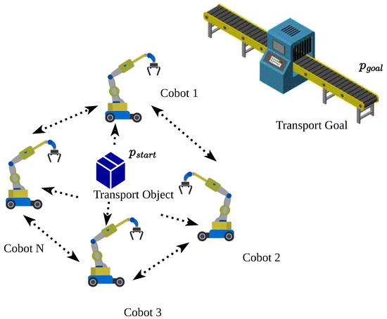
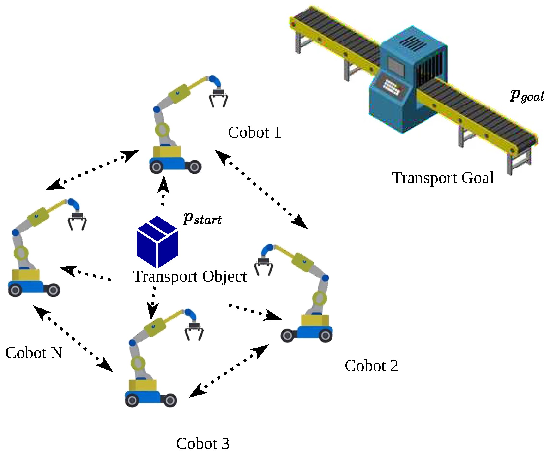
Advancements in computer, electrical, and mechanical engineering have significantly bridged the gap between humans and robots, fostering closer collaboration. These technological advances have led to the widespread adoption of collaborative robots (cobots) across industries [1]. Unlike traditional robots, cobots are designed to assist or work alongside human operators within shared workspaces, offering enhanced safety, adaptability, and intuitive operation [2]. However, when a network of cobots works collaboratively to achieve a common goal, intermittent communication failures can disrupt coordination and task execution. This paper addresses these challenges by developing a robust decentralized navigation framework that enables a team of networked cobots to perform common tasks efficiently, even in the presence of intermittent communication interruptions. In particular, we consider a scenario in which a group of mobile manipulators cooperatively transport an object from one location to another, while overcoming challenges such as intermittent communication and dynamic environments. An illustration of the problem scenario is shown in Figure 1. A team of networked cobots surrounds an object at the starting position (), working together to transport it to a designated goal location () on a conveyor belt.
Figure 1.
Illustration of the problem scenario. Cobot N can be replaced by any number of cobots.
Traditional fixed-path robots have limited flexibility in dynamic environments, while cobots are equipped to handle diverse materials and operate within unstructured spaces [3]. Leveraging multiple robots to work cooperatively further enhances flexibility and robustness, allowing them to adapt to changing conditions and handle larger, heavier, and more complex objects than a single robot can handle. Applications of these types of cobots range from smart factories to warehouse automation as part of Industry 4.0 [4]. The development of decentralized navigation for a team of cobots under intermittent communication failures poses a significant challenge in undertaking common tasks, such as guiding robots through dynamic environments, avoiding obstacles, and planning collision-free paths. Such a decentralized navigation scheme requires the design of resilient control strategies that operate even when communication among robots is disrupted [5,6]. The following list summarizes the key contributions of this paper.
- A graph-theoretic approach to modeling cobot connectivity and interactions. A graph Laplacian is employed to enable decentralized control and coordination.
- An integrated control, navigation, and communication system for multi-cobot cooperative object transportation.
- The system is designed to maintain performance under limited and intermittent communication conditions.
- The proposed decentralized navigation scheme is validated using both a commercial simulator and physical robots, demonstrating its performance in a variety of environments.
1.1. Problem Formulation
Following Figure 1, we consider a group of N autonomous networked cobots denoted by the set . The pose (position and orientation) of the i-th, , cobot, , is denoted by the pose vector , where is the 2D position of the cobot’s mobile base operating on the planar ground and is the orientation. The problem is to develop a decentralized navigation and control strategy that directs a team of autonomous cobots that cooperatively transport an object from an initial position to a goal position in a 2D environment despite intermittent communication failure among them. To ensure stable transportation, cobots maintain a fixed relative Euclidean distance between them, defined by the desired formation configuration. Let denote the desired distance between cobot and cobot . The distance error between cobot and cobot at time t is defined as
where denotes the Euclidean norm. The formation error is defined as the sum of distance errors between all pairs of cobots in the formation, normalized by the sum of desired distances, given by
where represents the set of neighbors of cobot with which it communicates. The objective is to minimize the formation error while ensuring efficient task completion under intermittent communication. Denoting as the motion control input (typically actuator command) for cobot , the problem is to find
where represents the cobot kinematic model. represents the terminal navigation time, which under the context of this work is defined as the time when the object being transported reaches the goal position , or task completion time.
Realistically, the positions of the cobots are sampled at discrete time intervals , rather than continuously. The discrete-time formation error is expressed as
where is the total number of time steps. Denoting as the mean formation error over the navigation period, given by
we can therefore approximate the discrete-time formation error integral with
In the later experiments, we use the task completion time , the mean formation error , and the maximum formation error as the performance metrics to evaluate the proposed decentralized navigation scheme across various scenarios.
1.2. Mathematical Preliminaries
The communication network among cobots is modeled as a directed graph , where is the set of nodes (cobots) and is the set of edges. An edge indicates that cobot i can communicate with cobot j. The set of neighbors for the i-th cobot is . The network is characterized by the adjacency matrix with entries if and otherwise, and the degree matrix where is the degree of the outer node i [7]. The graph Laplacian matrix encodes the network topology and is central to our decentralized coordination approach, with entries
1.3. Paper Organization
The remainder of this paper is organized as follows. Section 2 provides a comprehensive review of the literature on multi-robot systems, cooperative object transportation, and path planning algorithms, highlighting the importance of decentralized control and robust communication in multi-robot coordination. Section 3 introduces the graph-theoretic framework used to model multi-robot communication networks. Section 4 presents the kinematic models of the cobots employed in this work, which form the basis for the design of the control and navigation systems. The proposed decentralized cobot navigation scheme is detailed in Section 5. Section 6 provides computer experiments using a commercial real-time robot simulator. This is followed by experimental results given in Section 7, which assess the robustness and effectiveness of the proposed method under real-world conditions. Section 9 gives conclusion and potential research directions.
2. Literature Review
The design and implementation of an effective multi-robot system for cooperative object transportation require advances in a variety of fields. A safe and adaptive transportation strategy is needed to ensure that the object is securely transported by robots. Furthermore, robust inter-robot communication maintains coordination and synchronization with each other. This section provides a concise review of the most relevant methods and algorithms in these areas.
2.1. Multi-Robot Transportation Strategies
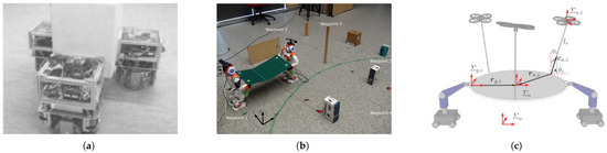
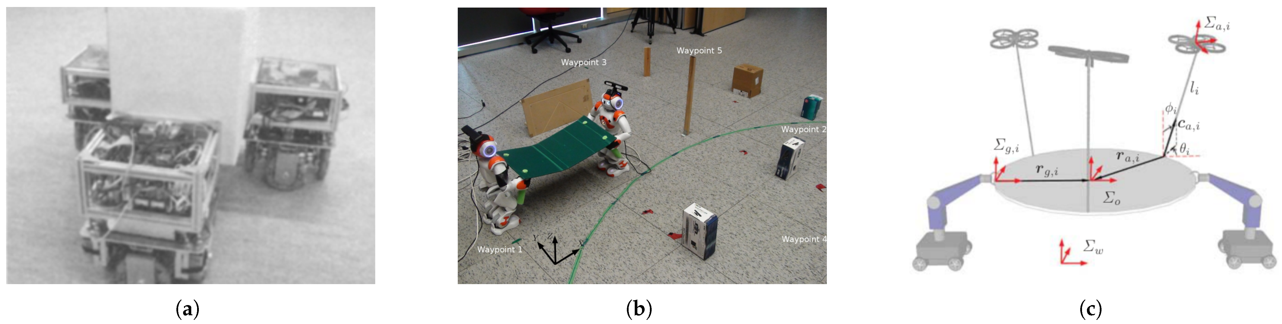
Coordination among multiple robots is essential for efficient object transport. Unlike single-robot systems, coordination among multiple robots requires decentralized control, information sharing, and path synchronization. Early work in [8] proposed decentralized force control to ensure object stability using multiple mobile robots, as shown in Figure 2a.
Figure 2.
Past work on multi-robot cooperative object transportation, including (a) decentralized push-pull strategy, (b) leader-follower control using two humanoid robots, and (c) heterogeneous team of ground and aerial robots.
Similarly, authors in [9] proposed a partitioning approach that treats the payload as a system of two coupled rigid bodies, leading to efficient coordination of two robot manipulators. Decentralized control strategies have been developed to maintain formations in multi-robot systems using robust control laws. Li et al. achieve coordinated path tracking for a team of robotic fish via a decentralized formation control scheme, ensuring finite-time convergence of the formation [10].
Coordination can be achieved using leader-follower frameworks, where a leader robot defines the path, and followers maintain alignment. This approach was implemented for humanoid robots transporting objects with zero-moment point (ZMP) control [11], as illustrated in Figure 2b. While effective, this framework is limited by the capabilities of the leader. Other studies propose graph-based coordination, where robots form a connected network and share information about their positions and goals. The graph Laplacian plays a vital role in decentralized coordination, allowing local control laws to converge to a global objective. For example, ref. [12] proposed a cooperative planner based on Anytime Repairing A* (ARA*) to allow humanoid robots to transport objects in obstacle-filled environments.
Recent efforts have focused on dynamic and heterogeneous teams of robots. Figure 2c demonstrates a multi-modal transportation system where ground and aerial robots work collaboratively. This approach allows for handling objects of varying shapes and weights, significantly enhancing the versatility of robotic systems [13].
Advancements in formation control under communication constraints have addressed challenges similar to those tackled in this work. Distributed coordination strategies that maintain network connectivity while achieving formation objectives have been developed for various multi-robot scenarios. However, many of these approaches rely on continuous communication or provide theoretical frameworks without practical hardware validation. The division-of-labor architecture employed in this work, where a scout robot handles exploration and path planning, while transporter robots maintain formation control, provides a practical alternative that balances computational efficiency with robustness. This hybrid approach differs from purely distributed methods by leveraging task specialization while maintaining decentralized execution during the transportation phase.
These prior strategies highlight the potential and limitations of decentralized coordination in object transport tasks, motivating the need for a more robust and scalable framework as proposed in this work. Although the existing literature provides strong theoretical foundations in graph-based coordination, formation control, and communication protocols, realistic integration addressing intermittent communication through odometry-based fallback mechanisms and low-cost hardware implementation remains an open challenge that this work addresses.
2.2. Inter-Robot Communication Technologies
In any multi-agent system working toward a common goal, efficient real-time information exchange is key to effective coordination and synchronization. The most common protocols for wireless data transfer in multi-robot systems include Data Distribution Service (DDS), Robot Operating System (ROS), and Message Queuing Telemetry Transport (MQTT). DDS prioritizes real-time performance and fits multiple communication models, domains, and architectures. However, it suffers from performance and scalability problems in large distributed systems [14]. ROS, on the other hand, enables modular development, but its reliance on continuous links poses challenges in robustness. MQTT is recognized as a lightweight protocol that ensures reliable communication. However, its broker-based design (the message hub) can become a bottleneck to scaling up the robot network [15]. Table 1 summarizes the differences of the aforementioned technologies used for inter-robot communication.
Table 1.
Comparison of technologies used for multi-Robot communication.
Apart from selecting a suitable technology, the efficiency of inter-robot communication can also be improved by a well-designed coordination strategy. The study in [16] presented a hierarchical coordination architecture that emphasizes consensus-based communication among robots. The proposed hierarchy consists of three layers from top to bottom: team controller, vehicle supervisor, and maneuver controller. This hierarchical structure ensures that the robots are synchronized and coordinated in their actions. Another way to improve inter-robot communication is to analyze and optimize the communication topology. Graph-theoretic approaches can be used to model and control networked robots under directed, weighted communication topologies. Zheng et al. in [17] developed a distributed controller for multi-robot systems using a weight-unbalanced directed graph model to account for uneven communication links. The authors formulated the multi-robot control problem as a constrained quadratic program and propose a distributed neural-dynamics solver to optimize the robots’ motions. They prove system stability and validate performance with experiments, showing that the controller can synchronize and coordinate redundant robots despite unbalanced network connectivity.
2.3. Handling Intermittent Communication in Multi-Robot Systems
For a multi-robot network, intermittent communication is a common challenge that can severely impact system performance. Intermittent communication refers to scenarios where communication links between robots are temporarily disrupted or lost. Such disruptions can arise from environmental factors, including radio frequency (RF) interference from metallic structures in industrial environments, signal attenuation due to obstacles or distance, and electromagnetic interference from machinery. Network congestion can cause packet loss or delays during high network traffic in shared wireless networks. Hardware limitations, such as temporary antenna orientation issues during robot motion or transient network hardware failures, can also disrupt communication. A common fallback strategy, such as stopping motion after communication loss, can lead to jerky and disruptive robot behavior. The authors in [18] compute for each differential-drive robot a safe time horizon over which it can continue moving without new commands. In their work, the robot motion is modeled by
where is the robot position, its heading, v its linear velocity, and its angular velocity. The reachable set is the set of all positions that the robot could occupy after time t under any admissible inputs . Because this set is non-convex and difficult to test directly, it is approximated by an ellipsoid
where , c is the predicted center, and is a positive-definite shape matrix that determines the size and orientation of the ellipsoid. The membership tests in give a conservative estimate of where a robot might be. At every update, robot i receives its next control command and computes the longest time (bounded above by a constant L) such that its predicted open-loop trajectory under remains outside all ellipsoids of neighboring robots’ for all times . If communication fails, robot i continues to execute for seconds and then stops, guaranteeing collision avoidance during that window. Because true reachable sets are enclosed by outer approximations, can produce ellipsoids much larger than the actual space a robot can occupy, leading to conservative safe horizons and robots stopping earlier than necessary. The guarantee also assumes exact state information and perfect actuation; uncertainty, latency, or tracking error are not explicitly accounted for. The derivation exploits the simple unicycle dynamics above, therefore extensions to higher-order or heterogeneous robots are nontrivial.
The control strategy in [19] explicitly accounts for network-induced delays and uses Lyapunov-based analysis to prove the finite-time stability and convergence of the formation. Building on this, the authors conclude that a fuzzy adaptive leader-follower bipartite formation controller with obstacle avoidance using artificial-potential-field strategy can maintain fast finite-time performance under practical limitations such as unknown bounded delays, actuator saturation, and bias faults to protect physical-layer safety. Their improved Lyapunov-Krasovskii construction is central to this claim, as it leverages time-delay information to preserve stability and avoid singularity issues in the control design. These results suggest that, for multi-robot networks with persistent but bounded communication latency, one can still aim for aggressive convergence guarantees without sacrificing safety behaviors. Lyapunov-Krasovskii analysis was also employed by Chang et al. to address time-varying delays [20]. However, the two works did not account for other network uncertainties such as packet dropouts, long blackout intervals, or rapidly switching connectivity.
Recent studies have explored techniques to increase the overall robustness of distributed multi-robot networks. Shi et al. showed a way to make distributed localization more reliable when some shared information may be wrong or malicious. The proposed method helps network agents maintain accurate position estimation even when parts of the communication are disrupted or manipulated, and it remains stable under those conditions [21]. This offers a principled way to handle the intermittent trust and time-varying connectivity typical of mobile teams. By keeping localization reliable under bad input, the method improves the downstream accuracy of shared plans and maps, reducing rework and unnecessary corrective messaging across the team. Ref. [22] proposes a zero-trust-based privacy-preserving distributed iterative localization method for mobile robot networks, motivated by threats from both malicious internal nodes and external eavesdroppers and by time-varying neighbor availability. Using this, a multi-cobot network can improve resilience against compromised teammates, reduce the value of intercepted messages, and enable collaboration in mixed-trust or contested environments while maintaining team-level convergence.
Recent work in connectivity-aware planning has emphasized maintaining communication links as explicit constraints in multi-robot coordination. These approaches often require sophisticated optimization frameworks that balance task objectives with the preservation of the network topology. In contrast, our approach adopts a pragmatic strategy where intermittent communication is handled through odometry-based state estimation and conservative safety thresholds, allowing the system to continue operation with degraded but sufficient coordination. This design philosophy prioritizes practical implementation and robustness over optimality, making it particularly suitable for industrial applications where cost-effectiveness and reliability are paramount.
2.4. Comparative Analysis
Table 2 provides a comprehensive comparison between existing works in multi-robot coordination and the approach proposed in this paper. While many existing approaches provide theoretical frameworks or focus on specific aspects of multi-robot coordination, this work integrates multiple techniques into a practical, validated system that addresses intermittent communication through odometry-based fallbacks and demonstrates performance on low-cost hardware platforms.
Table 2.
Comparison of related works in multi-robot transportation and communication.
The cobot network requires not only effective path planning and robust control mechanisms, but also reliable communication mechanisms to ensure seamless coordination among robots. This need for reliable communication is further addressed by graph-theoretic models, which offer a structured framework for organizing and coordinating multi-robot actions. Such models are particularly suited for complex systems involving multiple agents interacting in diverse environments. By integrating these graph-theoretic approaches into the system architecture, we can enhance coordination and adaptability, especially considering the challenges posed by intermittent communication. This integration not only addresses the structural needs of multi-robot systems, but also ensures that coordination strategies and protocols contribute to overall system performance. The contribution of this work lies in demonstrating how established techniques from graph theory, formation control, and communication protocols can be integrated into a cohesive, implementable system that maintains performance under real-world communication uncertainties, validated through both simulation and physical hardware experiments.
3. Graph Theoretic Model
In decentralized multi-robot systems, effective coordination relies on the underlying communication network that enables robots to exchange information and maintain task synchronization [23]. The structure of this network is naturally represented by a graph, where nodes correspond to robots, and edges denote communication links. The Laplacian matrix representation of the graph models the information flow among cobots, so that they work as a team to transport a package to the destined location, as illustrated in Figure 1, while avoiding collision with other cobots and the environment. Due to communication delay and intermittent communication, , where is the pose of cobot at time t, is not always synchronized across the network. A consensus algorithm is a distributed protocol that enables multiple agents in a network to reach agreement on a shared value or state, even when each agent only has access to local information from its neighbors. For networked cobots, the consensus algorithm ensures that in the event of network disruptions, the robots can still converge to a consistent value of in real time, enabling them to independently adjust their individual poses accordingly. The continuous-time consensus model is
where is the Laplacian matrix. This formulation enables each robot to compute control inputs using only local neighbor information, achieving global formation objectives through distributed computation. Critically, the Laplacian-based consensus protocol is inherently decentralized, in which cobot only needs to know the states of its immediate neighbors in rather than the complete network state, and all cobots execute identical control laws in parallel without requiring a central coordinator. The convergence rate is governed by the Fiedler value , with larger values indicating faster consensus. Specifically, among its eigenvalues , where N is the size of the matrix, the second-smallest eigenvalue (also known as the Fiedler value) quantifies the connectivity of the graph. Generally, a larger indicates faster convergence.
Intermittent communication is modeled through the time-varying nature of the communication graph. When communication links between cobots are temporarily disrupted, the corresponding edges in the directed graph become inactive, effectively modifying the adjacency matrix and consequently the Laplacian matrix at time t. During such disruptions, the affected edges have zero weight in , reflecting the temporary loss of communication links. As long as the algebraic connectivity for sufficient time intervals, the system can recover and maintain consensus once communication is restored. This graph-theoretic formulation provides a rigorous mathematical framework for analyzing system behavior under intermittent communication, enabling the design of robust coordination strategies that maintain formation control despite temporary network disruptions.
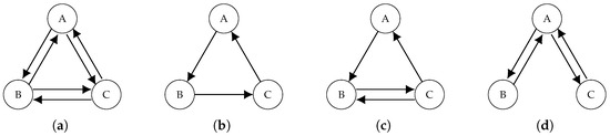
To illustrate the effect of topology on convergence, four network topologies for a system of three robots are analyzed: fully connected, cyclic, cyclic with backlink and star topologies, shown in Figure 3.
Figure 3.
Graph topologies for three-robot systems: (a) fully connected, (b) cyclic, (c) cyclic with back link, and (d) star topology.
The four topologies are designed to vary in data efficiency and redundancy, drawing inspiration from the coupled network and control relationships in a closed-loop communication system as described in [24]. The Laplacian matrices, eigenvalues, and convergence properties are examined.
In a fully connected topology seen in Figure 3a, every robot communicates with all other robots, resulting in the highest connectivity. The eigenvalues of the Laplacian matrix are , with , indicating fast convergence. However, this topology requires significant communication bandwidth and computational resources. On the other hand, in the cyclic topology, each robot connects to its immediate neighbors, forming a closed loop, as shown in Figure 3b. The graph Laplacian eigenvalues are . The presence of complex eigenvalues indicates oscillatory convergence, leading to slower task completion. Adding a backlink to the cyclic topology improves connectivity, as seen in Figure 3c. The new graph Laplacian has eigenvalues . This topology achieves faster convergence compared to the simple cyclic network, as indicated by the larger . Finally, for a star topology illustrated in Figure 3d, one robot serves as the central hub, while others connect only to it. The eigenvalues are . The star topology has a lower algebraic connectivity , leading to slower convergence, but it offers better fault tolerance since peripheral nodes can continue operating if one fails.
Table 3 summarizes the Laplacian eigenvalues, algebraic connectivity, and convergence rates for the four network topologies.
Table 3.
Comparison of network topologies shown in Figure 3.
The graph Laplacian provides a mathematical framework to model and analyze multi-robot coordination under different network configurations, or topologies. Fully connected networks achieve the fastest convergence, but they are expensive in bandwidth usage. The cyclic topology has oscillatory convergence due to complex eigenvalues, while adding a backlink improves convergence. Star topologies offer fault tolerance, but have slower convergence rates. These insights guide the design of networked cobots, where a balance is required between convergence speed, fault tolerance, and communication bandwidth. For the proposed decentralized navigation method, a cyclic topology with backlink is chosen to ensure efficient communication and fast convergence, while maintaining robustness against intermittent communication failures.
4. Cobot Kinematic Model
This section presents the kinematics of each cobot for the proposed decentralized navigation strategy. Each cobot consists of a mobile platform and an articulated manipulator. We assume the manipulator has been pre-programmed for optimal object grasping with calibrated grip forces to prevent slipping. Since cooperative transportation operates at low velocities, the dynamic coupling between the mobile platform and the manipulator is negligible, validating the decoupled control architecture. The primary focus is on decentralized navigation and communication. Two wheeled locomotion mechanisms are considered: differential drive robots (DDR) and omnidirectional drive robots (ODR).
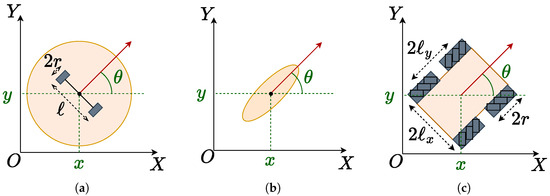
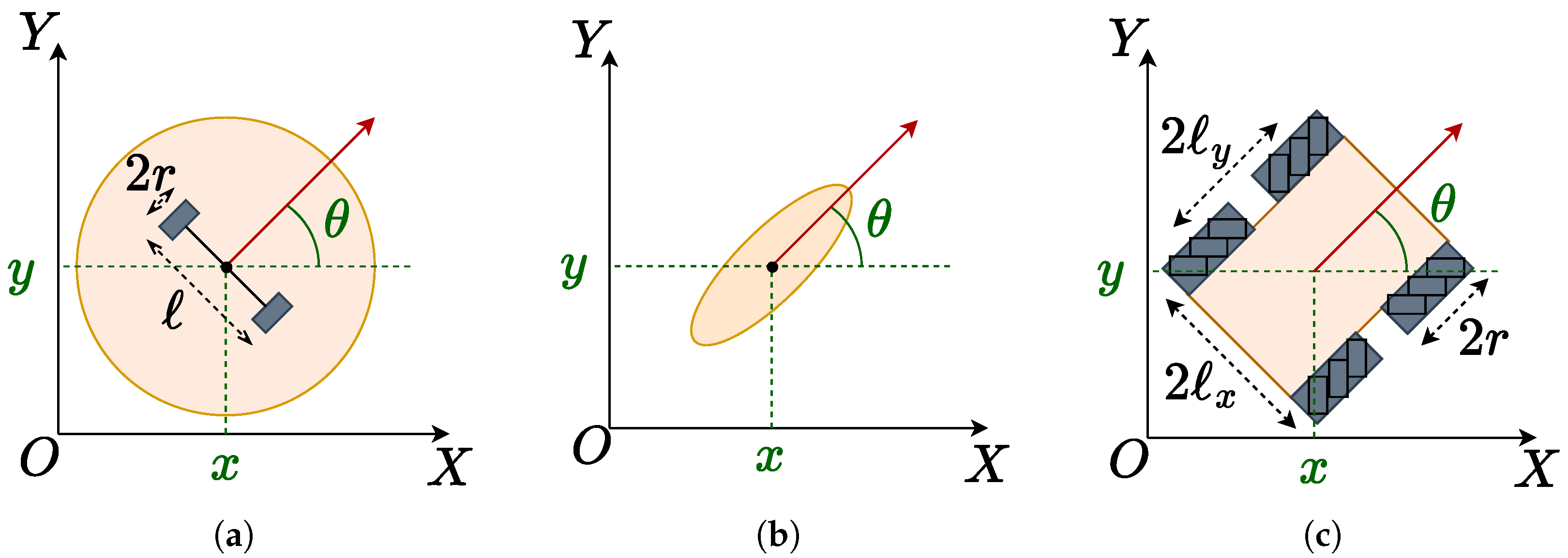
Forward kinematics computes the robot state from control inputs, enabling dead reckoning estimation. Inverse kinematics determines the control inputs needed to achieve the desired states. A DDR consists of two driving wheels (radius r) connected by an axle (length ℓ) and a castor wheel, as shown in Figure 4a.
Figure 4.
(a) Differential drive robot, (b) unicycle model, and (c) omnidirectional drive robot.
The control input specifies the angular velocities of the left and right wheels. The non-slip constraint
simplifies this to a unicycle model (Figure 4b) with linear velocity v and angular velocity :
The forward kinematics of the DDR system can therefore be expressed using linear and angular velocities as
with left and right wheel velocities of the i-th robot given by
Due to constraint (2), we control the desired velocities v and rather than directly.
The ODR uses Mecanum wheels with rollers at 45° to achieve holonomic motion in any direction. Figure 4c shows the ODR configuration, where r is the wheel radius and , are distances from center to wheel contact points.
The control input contains angular velocities of four independent wheels [25]. The forward kinematics is
The ODR is holonomic, with inverse kinematics
The DDR is non-holonomic with limited maneuverability, but is cost-effective, while the ODR offers holonomic flexibility at higher construction cost. We consider both types of robots to demonstrate the heterogeneity of the framework under various constraints.
5. Proposed Decentralized Cobot Navigation
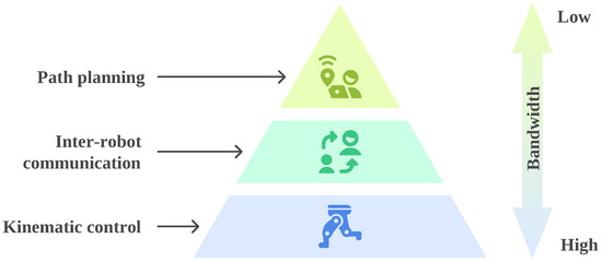
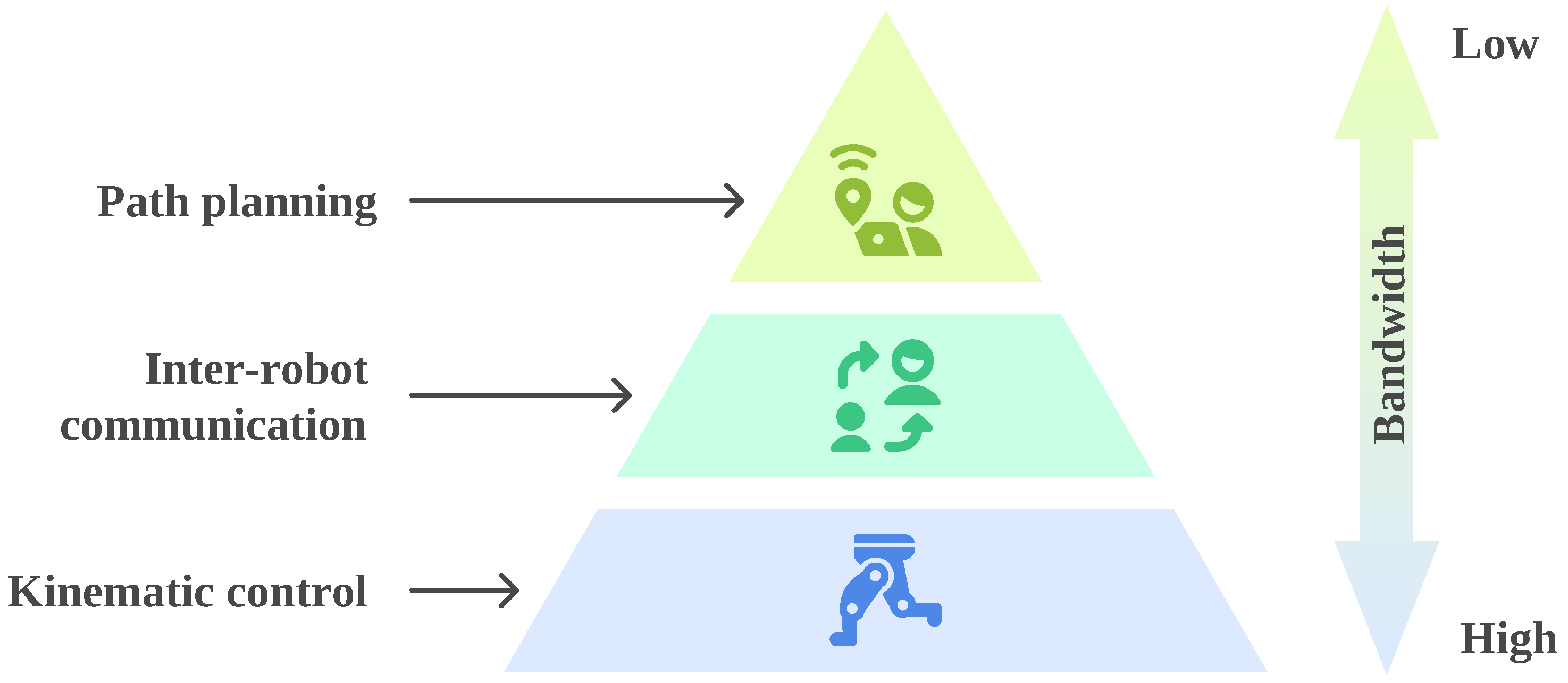
The autonomous navigation of networked cobots is designed for accuracy and robustness, as these are critical factors for ensuring seamless operation in dynamic environments. Additionally, the proposed method uses a decentralized design to ensure scalability and adaptability to different team sizes and robot capabilities. We propose a modular architecture that is organized into three distinct layers from bottom to top, namely kinematic control, inter-robot communication, and path planning. This layered approach is illustrated in Figure 5.
Figure 5.
The proposed autonomous navigation system for networked cobots, organized into three layers (courtesy of napkin.ai for help generating this figure).
The lowest layer, kinematic control, operates at the highest frequency and requires the most bandwidth for real-time actuator commands and sensor feedback. The inter-robot communication layer sits in the middle, exchanging state and coordination data at a moderate rate. The top layer, path planning, updates least frequently and thus demands the lowest bandwidth, as it deals with high-level decisions and trajectory updates. This structure ensures efficient resource allocation and scalable multi-cobot coordination. The subsequent portion of the section provides a detailed explanation of each layer.
5.1. Path Planning Layer
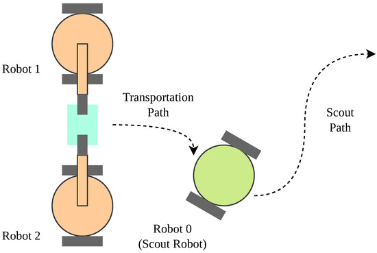
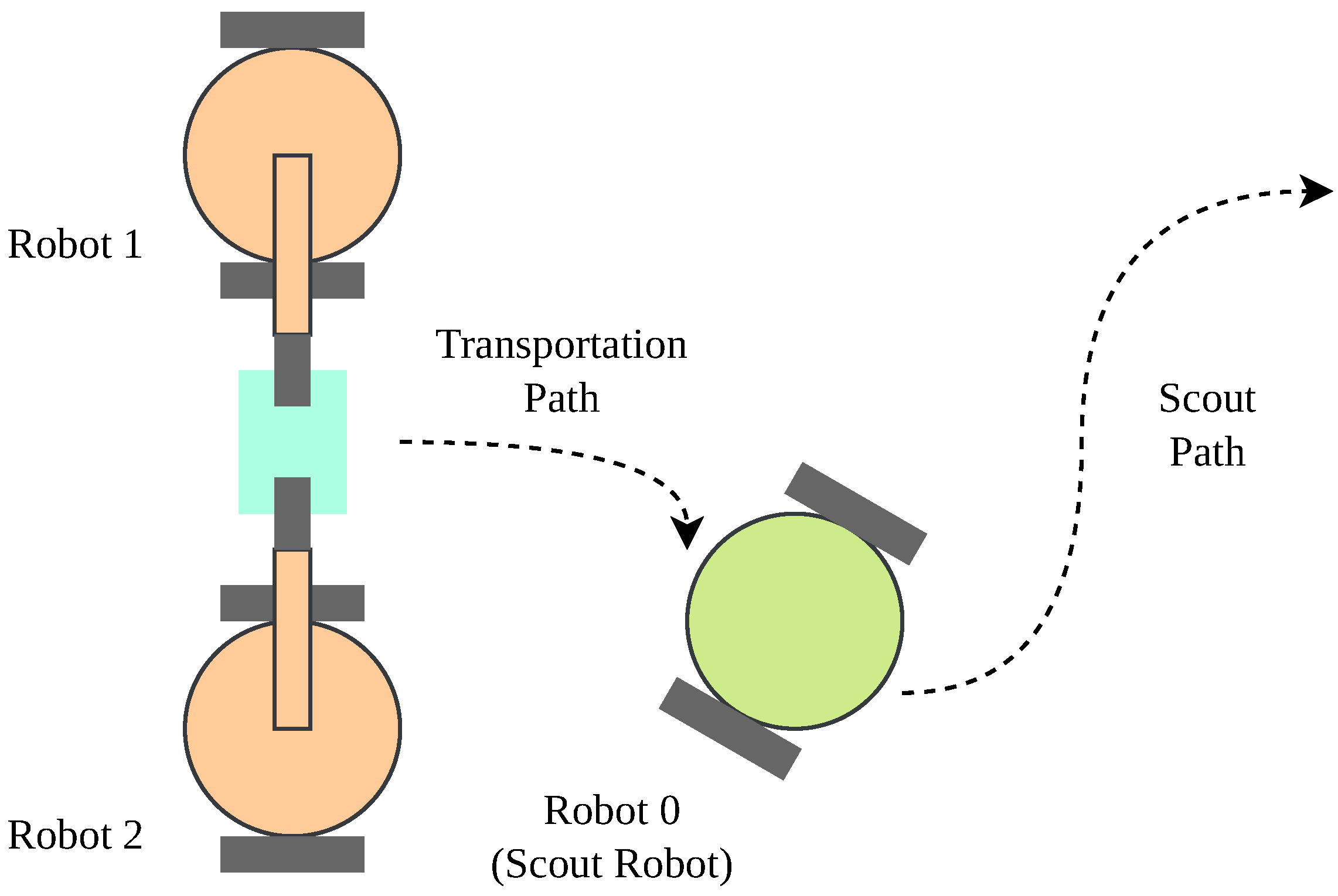
The top layer, path planning, involves real-time tracking of all cobot positions, dynamic task scheduling, and target location assignment based on current conditions and prioritized objectives. The robots’ vision of the real world relies on sensors and SLAM (Simultaneous Localization and Mapping) algorithms to estimate the pose and the environment map. SLAM requires the robot to move freely around the environment to build a map, which is essential for generating a path for the transportation task. However, when the two cobots actively transport the payload, their path is subject to the transportation task instead of the SLAM task. While performing the task, their observation of the environment is limited to nearby objects, such as the payload and the other cobot. This limitation may lead to a suboptimal path. To address this issue, we added an auxiliary cobot in the multi cobot system. This robot is responsible for exploring the environment, building a map, and planning an optimal path for future tasks, while the other cobots focus on the transportation task. We thereby name this cobot the scout robot. The scout robot is equipped with a more advanced sensor suite, such as a LiDAR or a depth camera, to build a more accurate map. The map is then used by the other cobots to plan their paths to complete the transportation. This is illustrated in Figure 6.
Figure 6.
A multi-cobot system with a scout robot and two transporter robots. In this paper, we label the scout robot with index 0, the left transporter robot with index 1, and the right transporter robot with index 2.
This division of labor allows the cobots to work collaboratively and efficiently, ensuring the success of the transportation task.
In cooperative transportation tasks, path planning should begin with the consideration of the payload’s optimal trajectory. Using an occupancy grid map established using the scout robot, the A* method can be used to formally find a path from the start to the goal position. An occupancy grid map is a discretized representation of the environment where the robot operating range is divided into cells that indicate the probability of being occupied by an obstacle. At each step, when the search progresses, A* evaluates the neighboring grid cells with a cost function and selects the one with the lowest cost to expand. The cost function for a grid cell c is defined as
where is the “cost-so-far” to reach the grid cell c from the start grid, is an estimated cost unable to represent the estimated cost from cell c to the goal [26]. For the path planning problem, we use Euclidean distance for both and as a consistent heuristic. Let be the position of the grid cell c. The actual cost and the heuristic cost can be expressed as
In addition, to ensure there is enough space for the payload and transporter robots to navigate together, the search also filters out nodes that are within a certain distance from obstacles. The path generated by A* represents a series of waypoints for the scout robot to follow. As the scout robot moves along the path, the transporter robots attempt to maintain a formation with the scout robot while grasping the payload.
5.2. Inter-Robot Communication Layer
The second layer addresses inter-robot communication and coordination, where each agent maintains awareness of its own state as well as the states of other cobots in the network. This allows for the establishment of a robust communication network that enables synchronized task assignments and collaborative mission planning.
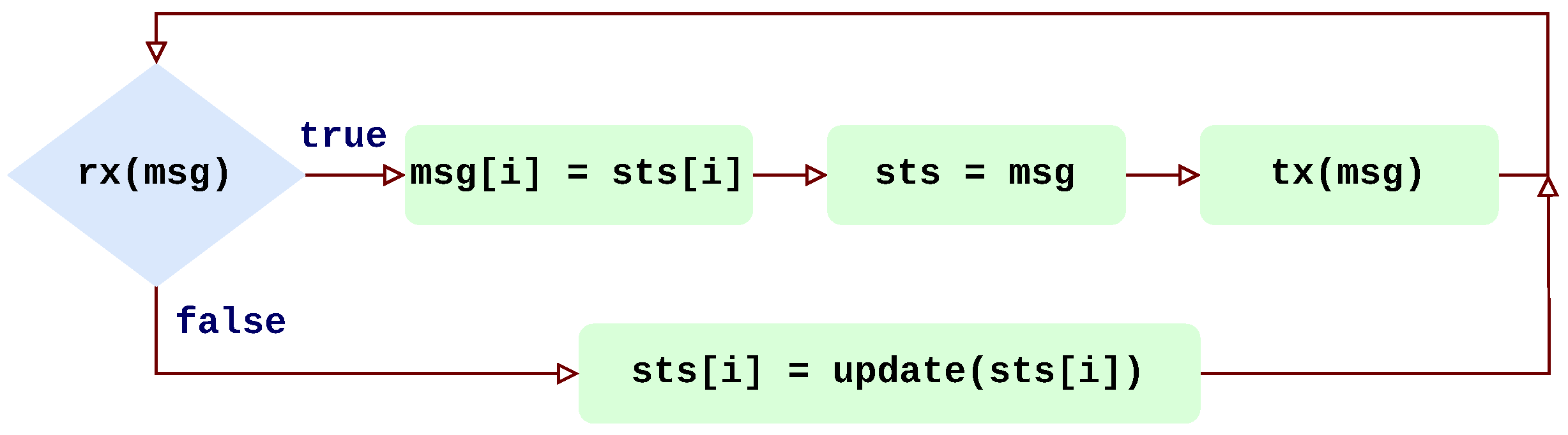
The top-level logic of the communication layer is illustrated in Figure 7.
Figure 7.
Flowchart of cobot i execution schedule in the communication layer.
The programmatic logic revolves around two variables, sts and msg. The first variable maintains a local cache of states and control inputs for all cobots, expressed mathematically as . sts[i] contains the ground truth data for cobot i, which is updated by reading from the kinematic control layer. The second variable, msg, functions as a buffer for message transmission and reception within the network, storing equivalent information but reflecting knowledge from other cobots. When cobot receives a message i (indicated by rx(msg) returning true), the system updates msg by incorporating the ground truth data specific to that cobot (msg[i]), after which it refreshes the local cache with the new information. Subsequently, the message is forwarded to the other cobots in the communication sequence (denoted as tx(msg)). Over the next iteration of the loop, when there is no message addressed to cobot i, the cobot updates its own cache by reading from the kinematic control layer. The sequence of communication is governed by the network topology, where messages are transmitted between nodes representing each cobot according to the edges in the graph representation. This method of inter-robot communication, characterized by a fully decentralized peer-to-peer approach, minimizes local computation and ensures timely propagation of updates across the network. There is no central message broker or coordinator. Instead, each cobot maintains its own local cache and directly exchanges messages with neighbors according to the network topology, making the system resilient to single-point failures.
When cobots are deployed in industrial environments, wireless communication is often subject to packet loss, latency, and jitter, which can lead to intermittent communication. In the context of cooperative object transportation, intermittent communication can cause the cobots to lose track of each other, deviate from the planned path, or even collide with each other. To address this issue, apart from employing fast converging network topologies, we implemented a communication handling method that increases the robustness of the cooperative object transportation system. This method is summarized in Algorithm 1.
| Algorithm 1 Pseudocode when cobot i loses connection |
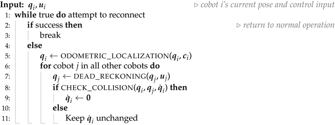 |
When cobot i loses connection, it enters a loop that attempts to reconnect to the network. If the reconnection is successful, the cobot returns to normal operation (lines 2–3). If the reconnection fails, the cobot estimates its pose using odometric localization technique based on forward kinematics in (3) or (5), since the encoder readings are locally available (line 5). The other cobots’ poses are predicted using dead reckoning, which is a navigation technique that estimates the cobot’s position based on its previous position and the last known control input. This can be broken down into two steps. First, the control input is used to derive the velocity of cobot j using forward kinematics expressed in (3), as shown in line 7. Then, the predicted pose is updated with Euler integration over the time-lapse from the last iteration ,
The predicted poses are then used to ensure that the cobot i maintains a safe distance from the other cobots. The collision check function evaluates whether cobot i is on a collision course with cobot j based on their predicted poses and the current velocity of cobot i (line 8). In our implementation, we define the collision condition as the euclidean distance between the two cobots being less than a predefined safety threshold :
We make sure that is larger than the sum of the radii of the two cobots to account for their physical dimensions. When the collision check function returns an unsafe condition, the velocity of cobot i is set to zero to prevent any movement (lines 9–10). This fail-safe mechanism prioritizes safety over task completion, ensuring that robots will not collide or deviate dangerously from safe trajectories even during extended communication blackouts. In industrial settings, can be determined based on the size of the cobots, the payload, and the safety regulations of the environment. There are various other methods to implement the collision check function, such as the safe time horizon method illustrated in [18]. Otherwise, the cobot velocity i remains unchanged (lines 10–11). The intermittent communication handling ensures that the cobots can continue to operate even when the network is unstable, and reduces the risk of collision or deviation from the planned path. However, it relies on the assumption of reconnection within a reasonable time frame. Although this assumption is optimistic, the safety implications are addressed directly through the fail-safe mechanism in Algorithm 1. In the event that the connection cannot be reestablished or the reconnection time is too long, the cobots may need to be manually reset to prevent any potential hazards.
5.3. Kinematic Control Layer
The lowest layer in the architecture determines the control input for individual cobots that drives the cobot from current pose to desired pose . The desired pose of the scout robot is determined directly by the path planning layer, whereas the desired pose of the transporter robot is computed to maintain formation with other cobots. Specifically, we use two reference vectors, and at to define the relative positions between the scout robot and the transporter robots and , respectively. During the transportation task, the desired positions of the transporter robots are updated as
Considering a team of three cobots, the formation error in (1) can be expanded to
Since the desired distances between the transporter robots and the scout robot, and , also represent the lengths of the reference vectors, we have and . Consequently, when the transporter robots maintain their relative positions with respect to the scout robot, the formation error converges asymptotically to zero. The orientation of the transporter robots is set to face the same direction as the scout robot, i.e., .
With , we employ a proportional-integral controller to compute the velocity of the cobot based on the pose error, which can be expressed as
where and are the proportional and integral gains, respectively. This control law ensures convergence to the desired pose with minimal steady-state error. The computed velocity is then mapped to the control input using the inverse kinematics of the cobot. For ODR robots, the inverse kinematics can be used directly as expressed in (6). Due to non-slip constraints (2) of DDR robots, we first convert the desired velocity to linear velocity v and angular velocity using
then apply the inverse kinematics in (4) to compute the control input .
In summary, the proposed method integrates closed-loop kinematic control and path planning algorithm for real-time navigation. The multi-cobot network does not require a central controller, and each cobot independently computes its control actions using only local sensor measurements and neighbor state information communicated through the graph-theoretic network topology. This decentralization is achieved through the Laplacian-based consensus protocol that enables global coordination via local interactions, peer-to-peer communication without a central broker, and independent execution of identical control laws on each robot. The method is implemented using a three-layer architecture that can be scaled to any number of cobots without requiring centralized redesign. In the following sections, the method is evaluated in a physics-based simulation environment, as well as in real cobots.
6. Validation Using Real-Time Robot Simulator
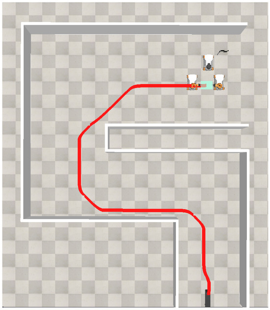
This section outlines the results obtained by applying the proposed methods in a simulated environment. The simulation is established with a robot simulator software, CoppeliaSim [27], which uses a physics engine and 3D models to simulate object dynamics in real time, and provides API for developing custom algorithms. The primary purpose of this simulation-based validation is to demonstrate the effectiveness of the proposed decentralized navigation approach in complex environments with dynamic obstacles and path planning requirements, which complements the physical robot experiments presented in Section 7 that focus on validating real-world robustness under practical constraints. We used KUKA YouBot as the cobot model, which is a desktop robot that has a 5-DOF manipulator arm mounted on a mobile platform driven by Mecanum wheels. This is shown in Figure 8.
Figure 8.
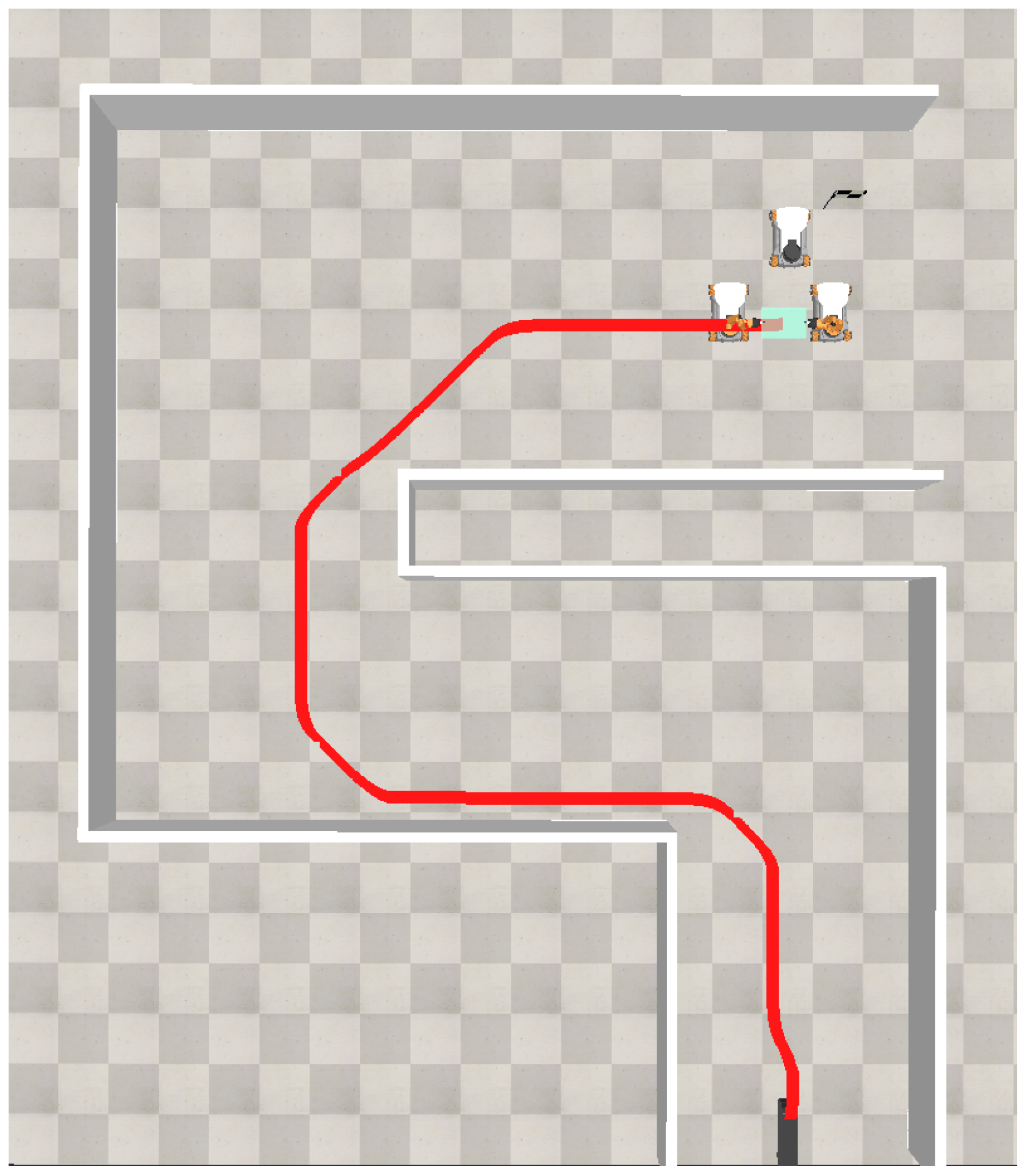
Trajectory of cobots carrying objects in Coppeliasim robot simulator.
Similar to the formation shown in Figure 6, two cobots are utilized to grasp the payload using their end effectors, applying sufficient normal force to generate friction at the contact surface and prevent slipping. The leading cobot lacks a manipulator to hold the payload; instead, it serves as the scout robot. This three-cobot team is tasked with transporting the payload from its initial location to the goal, marked by a flag. The cobots are expected to navigate around the walls efficiently en route to the target using the A* path planning algorithm. The cobot network employs a cyclic topology with a back link, illustrated in Figure 3c. Intermittent communication is simulated by randomly disconnecting links between cobots for specified time intervals. The simulation stress test the cobots’ ability to maintain formation under network instability, characterized by two parameters, the network dropout rate and the dropout duration . We empirically selected ten sets of experiments using = 0%, 10%, 15% and 20% and to evaluate the performance of the proposed method under varying levels of communication instability. The results are summarized in Table 4.
Table 4.
Simulation results using different sets of network dropout rates and dropout durations , recording the total task completion time , mean formation error , and maximum formation error .
Under nominal conditions (Exp. 1), the baseline task completion time is with a mean formation error of 0.055 and maximum error of 0.070. As communication degradation increases, the system maintains stable performance. At moderate dropout rates with short interruptions, task completion times remain nearly identical, which is within , and formation errors show minimal deviation. Exp. 10 is the most challenging scenario, with 20% dropout rate and interruptions, which exhibits the largest performance degradation. The formation error metrics scale more significantly with dropout duration than with dropout rate, indicating that prolonged communication blackouts pose greater challenges to formation maintenance than frequent but brief interruptions. These results validate the effectiveness of the proposed navigation scheme and confirm that the robots can successfully complete cooperative transportation tasks under simulated communication challenges.
To further analyze the performance of the proposed method, we selected a representative simulation trial with and for detailed examination. The trajectory of the payload is shown in Figure 8, where the red line represents the path taken by the payload during the simulation.
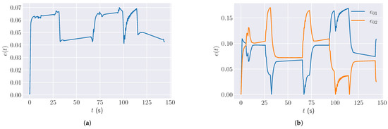
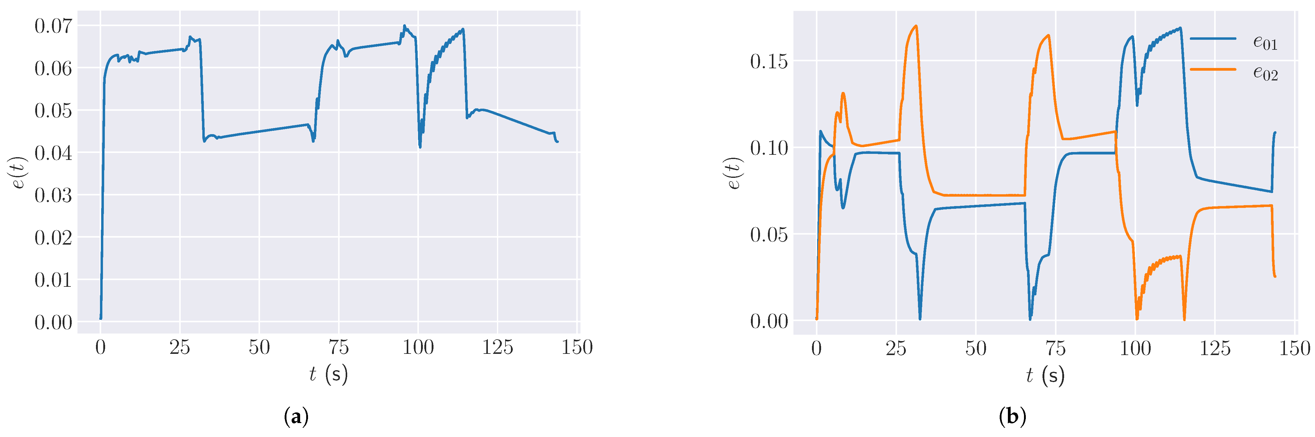
The formation error defined in (1) is plotted in Figure 9a during the simulation period.
Figure 9.
Formation error over time during the simulation: (a) cobot formation error , and (b) distances ( and ) between the scout robot and transporter robots.
At the beginning, is zero because the cobots start in their intended formation. As the simulation begins, increases rapidly to about 0.06 as the cobots accelerate and adjust to the initial movement. The plot then shows a pattern of sharp increases and sudden drops in error. Notable peaks occur around t = 30 s, 95 s and 110 s, corresponding to the moments when cobots make sharp turns at the corners of the walls. These turning maneuvers temporarily disrupt the formation, causing the error to spike. After each peak, the error drops rapidly as the cobots realign and recover their formation. Between these events, the error remains relatively stable, typically around 0.05, reflecting the system’s ability to maintain formation during straightforward navigation. Figure 9b displays individual distance errors and , which represent how far each transporter robot deviates from the payload during the simulation. The two curves exhibit visual symmetry: when increases, tends to decrease, and vice versa. This behavior indicates that when one cobot moves away from the payload due to turning at a corner, for example, the other compensates by moving closer, maintaining the overall formation. Distinct peaks in both and are observed around , which correspond to the same moments of disturbance as seen in Figure 9a.
Overall, the simulation demonstrates that the decentralized control strategy enables the cobots to recover from disturbances and maintain effective cooperation. The comprehensive stress testing revealed that the system exhibits robust performance under typical industrial communication conditions with low dropout rates and short interruption durations. However, performance degrades significantly when prolonged blackouts coincide with frequent dropouts, indicating operational limits where cumulative dead reckoning errors prevent formation maintenance. Although the simulation effectively evaluates algorithmic performance and communication resilience under various stress conditions, it does not capture real-world phenomena such as sensor noise, mechanical imperfections, and actual network behavior. In the subsequent section, we address these aspects through experiments using real, physical cobots.
7. Experiment Using Real Robots
The simulation in the previous section validates the performance of cobot team in complex scenarios with dynamic path planning using A* and obstacle avoidance. In this section, we conducted physical experiments that focus on validating robustness against real-world challenges difficult to model in simulation, such as sensor noise, actuator imperfections, mechanical backlash, hardware communication delays, network jitter, and intermittent wireless disruptions. This division of validation objectives allows for a comprehensive evaluation of both soundness and practical hardware viability.
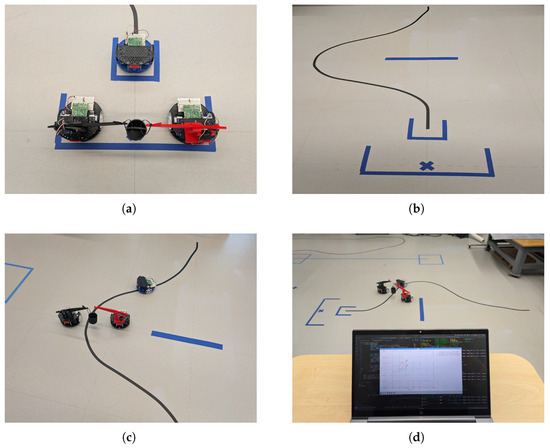
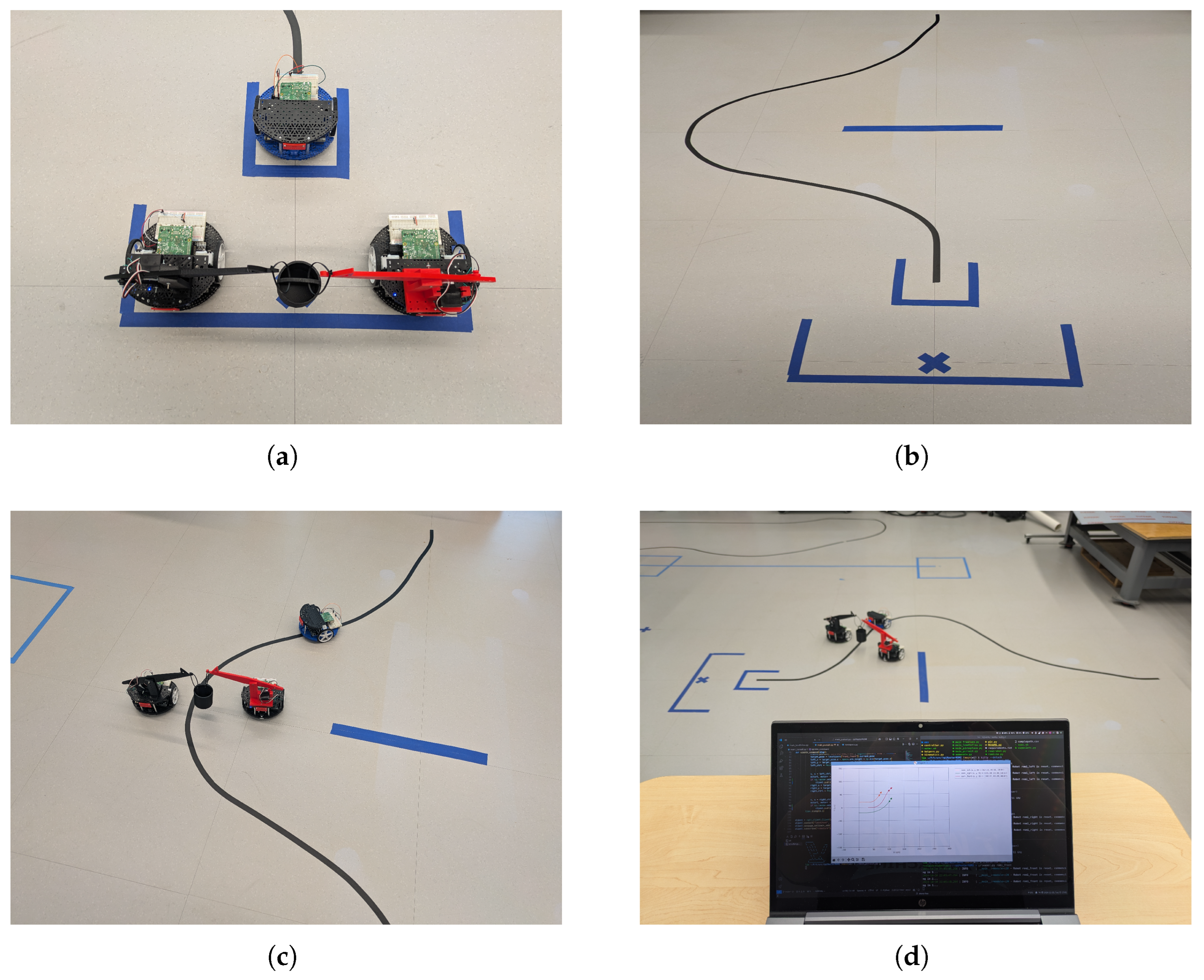
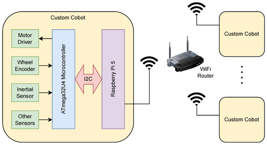
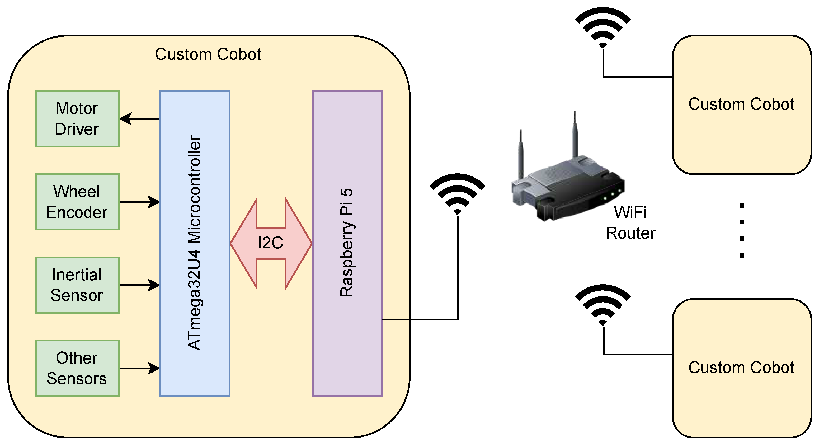
Considering the cost of deploying multiple YouBots, we decided to revise the cobots to a more cost-effective and customizable platform. The cobot team used this work is based on Romi mobile robots developed by Pololu Robotics and Electronics and a 3D printed manipulator arm as shown in Figure 10a. The Romi wheeled mobile robot is a small, low-cost robot platform made for competitive robotics, and therefore is easily customizable and expandable. The robot chassis is differential drive with two caster balls, and its circular shape allows for convenient turns or rotations in place. The printed circuit board mounted on the chassis has a microcontroller unit (MCU), motor drivers, wheel encoders, battery power circuitry, and inertial sensors. For our cobot implementation, the on-board MCU is programmed with a firmware that communicates with a Raspberry Pi single-board computer (SBC) over serial connection. Figure 11 illustrates the hardware architecture of our Romi cobot system.
Figure 10.
(a) Experimental setup with three cobots, (b) path to follow, (c) object is being transported, (d) performance monitoring in real-time.
Figure 11.
Customized cobots and their communication wireless network setup developed for conducting experiments.
The on-board electronic sensors and actuators are routinely interfaced with the MCU, which is responsible for low-level control of the cobot as a hardware abstraction layer, including motor control, encoder reading, and sensor data acquisition. The SBC runs high-level control algorithms, such as navigation, manipulation, and coordination, and sends control commands to the MCU. To facilitate multi-robot communication, the SBC is also connected to a wireless router, which allows for remote control and monitoring over a locally hosted MQTT network.
The three customized cobots were assembled for the scout robot (robot 0) and the transporter robots (robot 1 and 2), as seen in Figure 10a. Robot 0 is equipped with a light sensor array to follow the line path, and robots 1 and 2 are equipped with the manipulator arm. The line-following approach, while simplified compared to fully autonomous navigation, represents a practical and industrially relevant navigation method widely deployed in warehouses and manufacturing facilities due to its reliability and cost-effectiveness for structured environments.
The transporter robots follow the scout robot’s path to transport the payload, which is a basket whose handle is grasped by the manipulator arms of the transporter robots. For the real-world demonstration, a predetermined path was used due to practical constraints, including limited time, resources, and the cost of deploying advanced sensor suites for fully autonomous navigation. The path configuration of the scout robot is shown as the black curve in Figure 10b. The scenario allows the scout robot to recognize an obstacle ahead (the blue horizontal line) and plan a detour path to avoid it. During the experiment, the scout robot encounters a detected obstacle, marked by the blue line in Figure 10b, and plans a detour. Figure 10c shows a snapshot of the three cobots in a cooperative object transport task. The last image in Figure 10d shows the full experimental setup of the cooperative object transportation system. A laptop is connected to the wireless network, which allows for remote monitoring and control of the overall navigation of the team of cobots in real time. The window on the laptop screen shows a real-time visualization of the robots’ poses and the payload’s position, which is essential for debugging and monitoring the overall performance.
We conducted two sets of experiments using said cobot team. The first set lets the cobots perform the transportation task with no additional interference, while the second set introduces communication dropouts by having individual cobots reject incoming messages at a rate of 20% for . Table 5 summarizes the results of the two experiment sets.
Table 5.
Experimental results with physical cobots using different sets of network dropout rates and dropout durations , recording the total task completion time , mean formation error , and maximum formation error .
Comparing Exp. 11 to Exp. 12, the task completion time increased by only , while the mean formation error increased marginally from 0.069 to 0.074. The maximum formation error showed the most significant impact, rising from 0.046 to 0.132, which reflects the instantaneous deviations caused by communication loss. However, the system successfully completed the transportation task in both scenarios, validating that the proposed method maintains acceptable performance degradation even under severe communication disruptions, demonstrating practical viability for industrial applications where network reliability cannot be guaranteed.
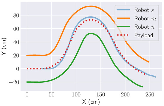
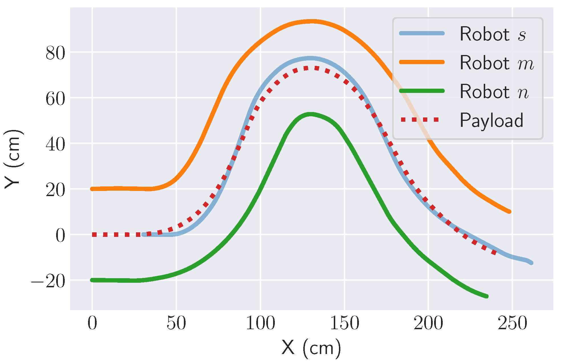
Figure 12 shows the trajectories of the three robots and the payload during Exp. 11.
Figure 12.
Trajectories of three robots and payload during the real-world experiment.
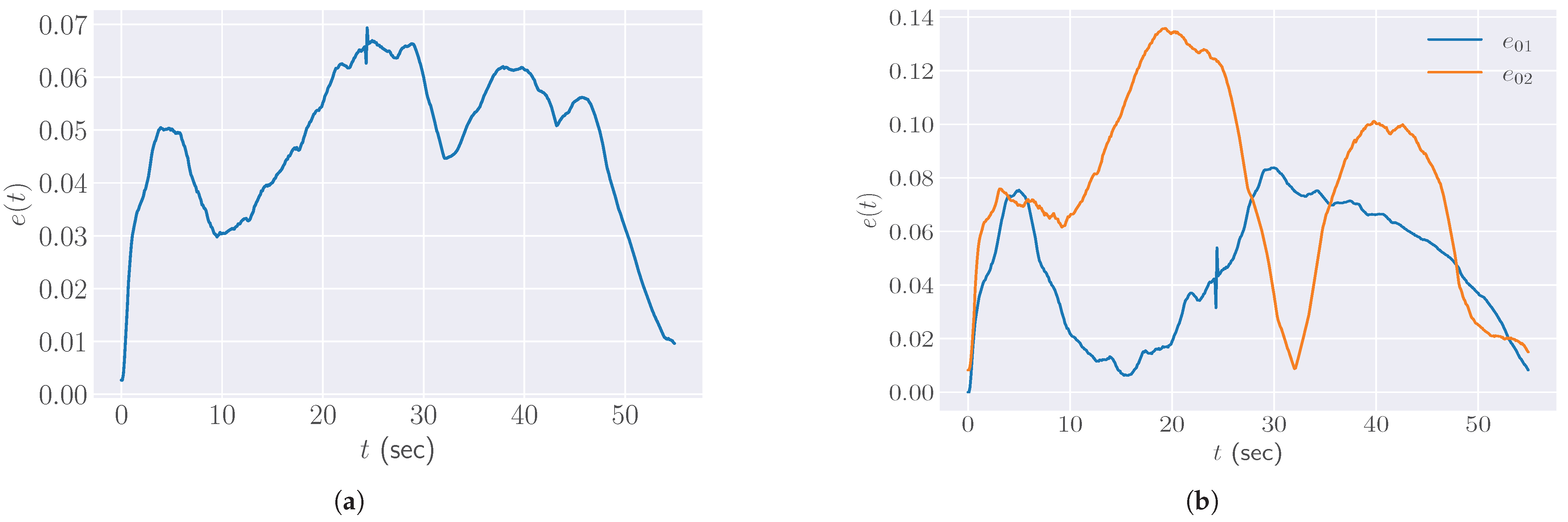
The plot in Figure 13a shows the formation error over time. The error initially rises as the cobots accelerate and synchronize their movements and then fluctuates as the task progresses. A pronounced spike can be observed around , which is attributed to a transient network interruption or communication delay between cobots. Despite this disturbance, the system shows resilience against communication loss, as the formation error quickly returns to its low level, indicating effective recovery and robust coordination. Toward the end of the experiment, the formation error stabilizes, suggesting that the system has overcome the most difficult parts of the path and is able to regain a stable formation. Individual distance errors and in Exp. 11 are plotted in Figure 13b, which shows the distance between the payload and each transporter robot over time.
Figure 13.
Formation error over time during the real-world experiment: (a) formation error over time, and (b) individual distance errors over time.
These errors reflect how well each cobot maintains its designated position relative to the scout robot. The two curves exhibit complementary behavior: when one cobot’s error increases, the other’s tends to decrease, indicating coordinated adjustments as the cobots navigate the path. The two individual error plots provide a more detailed view of how each cobot contributes to maintaining the formation, especially during challenging segments such as turns or obstacle avoidance.
The experiment results demonstrate that, despite transient disturbances, the robots successfully delivered the payload while maintaining a consistent proximity to the planned path. These results confirm that the decentralized control strategy can maintain formation and task progress even when communication is intermittently lost, validating its effectiveness in real-world conditions. Together with the simulation results presented in Section 6, which demonstrated the system’s capability to handle complex environments with dynamic obstacles and path planning, these physical robot experiments provide comprehensive validation of the proposed approach by addressing both environmental complexity (simulation) and real-world robustness (physical experiments) as complementary aspects of system performance.
8. Discussion
The experimental results reveal both strengths and limitations of the proposed approach. The formation errors in both simulation and experiments indicates consistent performance across platforms, suggesting that multi-cobot system can maintain formation effectively during cooperative transportation tasks. A notable limitation is the reliance on predetermined paths in physical experiments, contrasting with the dynamic A* path planning demonstrated in simulation. This choice was necessitated by practical constraints, including the cost limitations of deploying advanced sensor suites (e.g., LiDAR) and the time required for robust SLAM implementation. While line-following navigation is widely used in structured industrial environments [8], it restricts the system’s adaptability to changing layouts. This represents a trade-off between system complexity and practical deployability that is often encountered but rarely explicitly discussed in academic literature.
The scalability of the approach remains partially validated. While the graph-theoretic framework theoretically supports arbitrary numbers of robots through the Laplacian matrix formulation, empirical validation was limited to three cobots due to hardware availability and experimental space constraints. Future work should investigate whether the current MQTT-based communication architecture scales efficiently or becomes a bottleneck, and whether the formation control remains stable with larger N values where network delays and packet loss probabilities increase.
The MQTT-based communication architecture, while exhibiting the centralized broker bottleneck discussed in Table 1, proved adequate for the three-robot system. This choice prioritizes ease of implementation and debugging over theoretical optimality, reflecting pragmatic engineering decisions that are often necessary to translate research prototypes to working systems. However, for production deployment at scale, migration to DDS or implementing redundant broker architectures would likely be necessary to ensure reliability.
9. Conclusions and Future Work
In this paper, we focus on the navigation of a multi-robot system that can autonomously navigate and collaborate with each other to complete tasks in a shared workspace. In particular, we consider the problem of cooperative object transportation in an industrial environment using mobile robots with attached manipulators. The robots are required to work cooperatively, sharing information and coordinating their actions to achieve tasks efficiently. Using a graph-theoretic modeling framework in conjunction with forward and inverse kinematic theories, we propose a multi-layer programming architecture for the decentralized cobot navigation system. The system was validated in simulation and real-world environments, demonstrating its performance and robustness in various scenarios.
The work presented in this paper opens up several avenues for future research. First, while the manipulator subsystem was carefully fine-tuned in both simulation and experiments to ensure object stability during transportation, a comprehensive investigation of advanced manipulator control strategies represents an important direction for future work. Second, the current prototype lacks a robust localization mechanism. This could be improved by integrating more advanced sensors (such as LiDAR) and deploying state-of-the-art SLAM algorithms for better positioning accuracy. Finally, while this work demonstrates the feasibility of the decentralized architecture with three cobots, the proposed graph-theoretic framework and decentralized control are inherently designed for scalability. The approach presented in the paper can be tested in more complex, dynamic environments with moving obstacles and human presence to further evaluate its adaptability and robustness in real-world industrial scenarios.
Author Contributions
Conceptualization, Z.L. and M.S.M.; methodology, Z.L.; software, Z.L.; validation, Z.L.; formal analysis, Z.L.; investigation, Z.L.; resources, Z.L. and M.S.M.; data curation, Z.L.; writing—original draft preparation, Z.L.; writing—review and editing, Z.L. and M.S.M.; visualization, Z.L.; supervision, M.S.M.; project administration, M.S.M. All authors have read and agreed to the published version of the manuscript.
Funding
This research received no external funding.
Data Availability Statement
The original contributions presented in this study are included in the article. Further inquiries can be directed to the corresponding author(s).
Acknowledgments
During the preparation of this manuscript/study, the authors used Napkin AI online service for the purposes of generating Figure 5. The authors have reviewed and edited the output and take full responsibility for the content of this publication.
Conflicts of Interest
The authors declare no conflicts of interest.
References
- Colgate, J.E.; Wannasuphoprasit, W.; Peshkin, M.A. Cobots: Robots for Collaboration with Human Operators. In Proceedings of the ASME 1996 International Mechanical Engineering Congress and Exposition. Dynamic Systems and Control, Atlanta, GA, USA, 17–22 November 1996; American Society of Mechanical Engineers Digital Collection; American Society of Mechanical Engineers: New York, NY, USA, 2023; pp. 433–439. [Google Scholar] [CrossRef] [Scilit]
- Franklin, C.S.; Dominguez, E.G.; Fryman, J.D.; Lewandowski, M.L. Collaborative Robotics: New Era of Human–Robot Cooperation in the Workplace. J. Saf. Res. 2020, 74, 153–160. [Google Scholar] [CrossRef] [Scilit] [PubMed]
- Zhou, K.; Ebenhofer, G.; Eitzinger, C.; Zimmermann, U.; Walter, C.; Saenz, J.; Castaño, L.P.; Hernández, M.A.F.; Oriol, J.N. Mobile Manipulator Is Coming to Aerospace Manufacturing Industry. In Proceedings of the 2014 IEEE International Symposium on Robotic and Sensors Environments (ROSE), Timisoara, Romania, 16–18 October 2014; pp. 94–99. [Google Scholar] [CrossRef] [Scilit]
- Sahan, A.S.; Kathiravan, S.; Lokesh, M.; Raffik, R. Role of Cobots over Industrial Robots in Industry 5.0: A Review. In Proceedings of the 2023 2nd International Conference on Advancements in Electrical, Electronics, Communication, Computing and Automation (ICAECA), Coimbatore, India, 16–17 June 2023. [Google Scholar] [CrossRef] [Scilit]
- Villani, V.; Pini, F.; Leali, F.; Secchi, C.; Fantuzzi, C. Survey on Human-Robot Interaction for Robot Programming in Industrial Applications. IFAC-PapersOnLine 2018, 51, 66–71. [Google Scholar] [CrossRef] [Scilit]
- Realyvásquez-Vargas, A.; Cecilia Arredondo-Soto, K.; Luis García-Alcaraz, J.; Yail Márquez-Lobato, B.; Cruz-García, J. Introduction and Configuration of a Collaborative Robot in an Assembly Task as a Means to Decrease Occupational Risks and Increase Efficiency in a Manufacturing Company. Robot. Comput.-Integr. Manuf. 2019, 57, 315–328. [Google Scholar] [CrossRef] [Scilit]
- Chung, F.; Lu, L.; Vu, V. Spectra of Random Graphs with given Expected Degrees. Proc. Natl. Acad. Sci. USA 2003, 100, 6313–6318. [Google Scholar] [CrossRef] [Scilit] [PubMed]
- Wang, Z.; Takano, Y.; Hirata, Y.; Kosuge, K. Decentralized Cooperative Object Transportation by Multiple Mobile Robots with a Pushing Leader. In Distributed Autonomous Robotic Systems 6; Alami, R., Chatila, R., Asama, H., Eds.; Springer: Tokyo, Japan, 2007; pp. 453–462. [Google Scholar] [CrossRef] [Scilit]
- Dong, F.; Yu, B.; Zhao, X.; Chen, S.; Liu, H. An Evenly Partition Approach to the Modeling and Constraint-Following Control for the Spatial Cooperative Dual-Robot-System. J. Dyn. Syst. Meas. Control 2023, 145, 111003. [Google Scholar] [CrossRef] [Scilit]
- Li, D.; Sun, Y.; Zeng, L.; Law, R.; Xu, Y.; Wu, E.Q.; Zhu, L. Finite-Time Terminal Sliding Mode-Based Formation Control Scheme for a Robotic Fish. IEEE Trans. Ind. Informat. 2025, 21, 5922–5932. [Google Scholar] [CrossRef] [Scilit]
- Kajita, S.; Kanehiro, F.; Kaneko, K.; Fujiwara, K.; Harada, K.; Yokoi, K.; Hirukawa, H. Biped Walking Pattern Generation by Using Preview Control of Zero-Moment Point. In Proceedings of the 2003 IEEE International Conference on Robotics and Automation, Taipei, Taiwan, 14–19 September 2003; Volume 2, pp. 1620–1626. [Google Scholar]
- Rioux, A.; Esteves, C.; Hayet, J.B.; Suleiman, W. Cooperative Vision-Based Object Transportation by Two Humanoid Robots in a Cluttered Environment. Int. J. Humanoid Robot. 2017, 14, 1750018. [Google Scholar] [CrossRef] [Scilit]
- Lippi, M.; Marino, A. Cooperative Object Transportation by Multiple Ground and Aerial Vehicles: Modeling and Planning. In Proceedings of the 2018 IEEE International Conference on Robotics and Automation (ICRA), Brisbane, QLD, Australia, 21–25 May 2018; pp. 1084–1090. [Google Scholar] [CrossRef] [Scilit]
- Gambo, M.L.; Danasabe, A.; Almadani, B.; Aliyu, F.; Aliyu, A.; Al-Nahari, E. A Systematic Literature Review of DDS Middleware in Robotic Systems. Robotics 2025, 14, 63. [Google Scholar] [CrossRef] [Scilit]
- Saboia, M.; Clark, L.; Thangavelu, V.; Edlund, J.A.; Otsu, K.; Correa, G.J.; Varadharajan, V.S.; Santamaria-Navarro, A.; Touma, T.; Bouman, A.; et al. ACHORD: Communication-Aware Multi-Robot Coordination with Intermittent Connectivity. IEEE Robot. Autom. Lett. 2022, 7, 10184–10191. [Google Scholar] [CrossRef] [Scilit]
- Speranzon, A. Coordination, Consensus and Communication in Multi-Robot Control Systems. Doctoral Thesis, KTH School of Electrical Engineering, Stockholm, Sweden, 2006. [Google Scholar]
- Jia, Y.; Song, Y.; Cheng, J.; Jin, J.; Zhang, W.; Yang, S.X.; Kwong, S. A Deep Reinforcement Learning Approach Using Asymmetric Self-Play for Robust Multirobot Flocking. IEEE Trans. Ind. Inform. 2025, 21, 3266–3275. [Google Scholar] [CrossRef] [Scilit]
- Mayya, S.; Egerstedt, M. Safe Open-Loop Strategies for Handling Intermittent Communications in Multi-Robot Systems. In Proceedings of the 2017 IEEE International Conference on Robotics and Automation (ICRA), Singapore, 29 May–3 June 2017; pp. 5818–5823. [Google Scholar] [CrossRef] [Scilit]
- Chang, Z.; Zong, G.; Song, S.; Zhao, X. Fast Finite-Time Bipartite Formation with Obstacle Avoidance for Time-Delay Multiagent Systems: Application in Mobile Robot Swarm. IEEE Trans. Ind. Inform. 2025, 21, 4586–4594. [Google Scholar] [CrossRef] [Scilit]
- Chang, Y.H.; Yang, C.Y.; Lin, H.W. Robust Adaptive-Sliding-Mode Control for Teleoperation Systems with Time-Varying Delays and Uncertainties. Robotics 2024, 13, 89. [Google Scholar] [CrossRef] [Scilit]
- Shi, L.; Chen, X.; Zhou, Y. Barycentric Coordinate-Based Distributed Localization for Wireless Sensor Networks Under False-Data-Injection Attacks. IEEE Trans. Cybern. 2025, 55, 1568–1579. [Google Scholar] [CrossRef] [Scilit] [PubMed]
- Shi, L.; Huang, D.; Zong, G.; Zhou, Y.; Cheng, Y. Zero-Trust-Based Privacy-Preserving Distributed Localization for Mobile Robot Networks. IEEE Trans. Autom. Control 2025, 1–14. [Google Scholar] [CrossRef] [Scilit]
- Li, Q.; Gama, F.; Ribeiro, A.; Prorok, A. Graph Neural Networks for Decentralized Multi-Robot Path Planning. In Proceedings of the 2020 IEEE/RSJ International Conference on Intelligent Robots and Systems (IROS), Las Vegas, NV, USA, 24 October 2020–24 January 2021; pp. 11785–11792. [Google Scholar] [CrossRef] [Scilit]
- Schwager, M.; Michael, N.; Kumar, V.; Rus, D. Time Scales and Stability in Networked Multi-Robot Systems. In Proceedings of the 2011 IEEE International Conference on Robotics and Automation, Shanghai, China, 9–13 May 2011; pp. 3855–3862. [Google Scholar] [CrossRef] [Scilit]
- Taheri, H.; Qiao, B.; Ghaeminezhad, N. Kinematic Model of a Four Mecanum Wheeled Mobile Robot. Int. J. Comput. Appl. 2015, 113, 6–9. [Google Scholar] [CrossRef] [Scilit]
- Hart, P.E.; Nilsson, N.J.; Raphael, B. A Formal Basis for the Heuristic Determination of Minimum Cost Paths. IEEE Trans. Syst. Sci. Cybern. 1968, 4, 100–107. [Google Scholar] [CrossRef] [Scilit]
- Rohmer, E.; Singh, S.P.N.; Freese, M. V-REP: A Versatile and Scalable Robot Simulation Framework. In Proceedings of the 2013 IEEE/RSJ International Conference on Intelligent Robots and Systems, Tokyo, Japan, 3–7 November 2013; pp. 1321–1326. [Google Scholar] [CrossRef] [Scilit]

Disclaimer/Publisher’s Note: The statements, opinions and data contained in all publications are solely those of the individual author(s) and contributor(s) and not of MDPI and/or the editor(s). MDPI and/or the editor(s) disclaim responsibility for any injury to people or property resulting from any ideas, methods, instructions or products referred to in the content. |
© 2025 by the authors. Licensee MDPI, Basel, Switzerland. This article is an open access article distributed under the terms and conditions of the Creative Commons Attribution (CC BY) license.