Abstract
The design and performances of a newly built electrostatic charge state analyzer constructed to act as a spectrometer for keV/u ions are reported. It consists of two curved electrodes enclosed by Matsuda electrodes. This setup was recently tested using Ar and Ar ion beams at an energy of 10 keV per charge unit. This spectrometer achieves a good separation of different charge states formed by electron capture processes during collisions between primary ions and the residual gas. Thanks to these first tests, we have identified up to three different background contributions on the detector that need to be reduced or suppressed.
1. Introduction
When studying ion-matter interaction, analyzing the ion charge state after the interaction is often one of the key parameters. It gives information about electronic processes at play. For that purpose, specific instruments are developed. They must be able to both separate the charge states after the interaction, count the number of ions whose charge state changed and reach performances allowing coincidence detection. Here, we present a multipurpose home-made ion spectrometer mainly developed for the FISIC (Fast Ion-Slow Ion Collision) project [1], but that can be used in any setups involving ion charge exchanges. The FISIC program aims to perform ion-ion collisions in an energy regime where cross-sections are barely known. The first collision systems will be studied using slow (keV/u) ion beams coming from the FISIC platform and fast (MeV/u) ion beams delivered by CRYRING@ESR (Heavy Ion Storage Ring Facility) [2]. The spectrometer will be placed downstream the collision zone to analyze the charge state of the slow ion beam. To measure absolute cross-sections of elementary electronic processes, coincidence measurements between slow and fast ion charge states after the collision zone are mandatory. The ion spectrometer must be charge dispersive for multicharged ions with keV/u energies, and must be able to count several charge states at once. We have chosen a full electrostatic system for which we present here the first tests performed at the ARIBE (French acronym for Accelerator for Research with Low Energy Ions) facility [3] in Caen, France. In this paper, we first discuss the design of the spectrometer with its associated detection system. Second, we present selected experimental results and their comparison with simulations made using the SIMION software [4]. To conclude, we present the limitations of the set-up as well as future upgrades considered to reduce the different background contributions.
2. Experiment and Results
2.1. Design of the Ion Spectrometer
The ion spectrometer is an electrostatic charge state analyzer (Figure 1)—see Ref. [5] for functioning principles. It is made of two curved electrodes to separate the charge states and two vertical electrodes called Matsuda electrodes [6] on the sides for the focusing and steering of the ion beams. A Faraday cup measures the primary beam intensity with a given charge state, and a position sensitive detector (two MicroChannel Plates (MCPs) with a delay-line resistive anode) images the position of the other charge states ()+, ()+, ... [7]. A repeller ring placed in front of the Faraday Cup is polarized to avoid losing electrons when the primary ion beam hits the Faraday Cup. This allows one to correctly measure the beam current. As shown on Figure 1, the 2D position sensitive detector is placed to record ions that have lower charge states than the ions entering the Faraday Cup. In order to guide the charge state in the Faraday cup, the voltages U on the curved outer and inner electrodes have to be as follows:
where is the primary charge state, V the extraction voltage of the ion source, R the curvature radius of the spectrometer, and the distance between the outer and inner electrodes. The values of R and are reported in Figure 1.
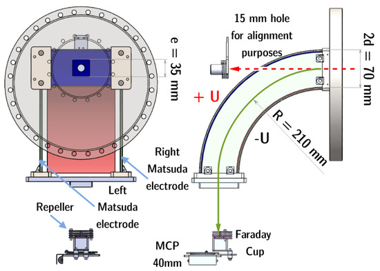
Figure 1.
(Left) Front view of the spectrometer showing the entrance square with side mm. (Right) Schematic cut through the ion spectrometer (side view). The expected ion trajectories for V = 10 kV and corresponding to V, and with V (for beam alignment purposes) are shown.
2.2. The ARIBE Facility
The ARIBE facility at GANIL (Caen, France) is composed of an ion source, a magnetic dipole to select ions with a given charge state, a beamline equipped with magnetic quadrupoles and steerers to monitor the beam shape, and a magnetic dipole to remove ions of other charge states from the primary beam leading to a secondary beamline, with its own set of quadrupoles and steerers, at the end of which our spectrometer was installed. All along the beamlines several slits, profilers and Faraday cups allow to monitor the beam shape and intensity. The experimental arrangement for the tests of the ion spectrometer is the same as the one for the charge state purification system (see details in Ref. [8]). The emittance of the beam is estimated to be lower than 5 mm mrad, achieved by closing the slits located upstream the last dipole. This was also meant to reduce the beam intensity, in an effort to avoid any damage on the MCPs. The beam intensities were comprised between 1 and 5 pA of 10 keV per charge unit argon beams, resulting in between 200 to 5000 hits per second on the MCPs.
2.3. Methodology
The tests presented here were carried out in November 2021 using both Ar and Ar beams. The pressure inside the ARIBE beamline and the spectometer was ≈ mbar. The primary charge state ions are driven through the ARIBE beamlines up to the entrance of the ion spectrometer. Starting from the last dipole, all along the last straight part of the beamline (corresponding to a 4 m length), primary ions may collide with the residual gas. As a consequence, electron capture processes may occur, thus leading to the production of secondary beams of lower charge states. Therefore, the in-going ion beam that enters the ion spectrometer consists of ions with the same kinetic energy but different charge states. There, depending on the voltages used, spacial dispersion of the different charge states takes place, allowing the separation between the primary beam recorded by a Faraday Cup and the secondary beams imaged by the MCP detector. Results are presented in the following section.
All results were obtained using a Fast Acquisition System for nuclEar Research (FASTER) acquisition card [9]. FASTER is a digital modular acquisition system that is able to perform charge and time of flight measurements. The experimental results were compared with simulations performed using the SIMION 3D suite [4,10].
3. Results
We carried out several tests for each primary charge state, where we changed the voltages on the outer and inner curved electrodes, and on the Matsuda electrodes. The results selected in this section were obtained with V. We chose to present the most visually representative of our results.
3.1. Results with Ar
The result presented here (see Figure 2) was obtained with a 4.7 pA Ar beam, with voltages on the left and right Matsuda electrodes of 1000 V and 1500 V respectively and the acquisition time was 250 s. On the MCPs and the repeller, we used respectively −500 V and −200 V. According to the simulations, we expect to have only one spot on the MCP detector, corresponding to the secondary Ar beam that originates from stabilized electron capture on residual gas in the beamline. The voltages are tuned in order to obtain the primary beam inside the Faraday cup. If it exists, the Ar beam is expected to hit the outer electrode a few centimeters above the exit aperture of the spectrometer. We measure one main spot corresponding to the expected position of Ar ions. A tail above this spot is extending towards the position of the Faraday cup (Figure 2). The tail represents of the main Ar peak. This tail results from electron capture occurring all along the Ar trajectory inside the spectrometer: the ions are thus partially deflected as Ar ions and Ar ions. This hypothesis has been confirmed by simulations (see Figure 2) where the electron capture process is modeled by a single charge change from Ar to Ar with no kinetic energy loss. The position of the capture process is chosen randomly along the trajectory of the primary Ar ions.
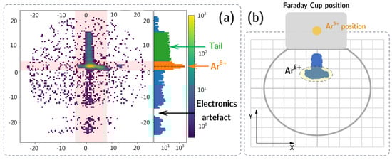
Figure 2.
A recorded MCP image with the use of Ar as the primary beam exhibits the Ar peak and its tail (a). Results of SIMION simulations carried out with the same voltages and beam parameters (b). The horizontal line where no detection occur has been found to be an electronic artefact of the MCP.
The uniform background present on Figure 2 is due to very low-energy (a few tens of eV) ions produced by ionization of the residual gas near the detector and which are attracted by the negative voltage applied on the front face of the detector. This uniform background corresponds to of the hits on the detector.
3.2. Results with Ar
The result presented here (see Figure 3) was obtained with a 1.5 pA Ar beam, with voltages on the left and right Matsuda electrodes of 1000 V and 2000 V, respectively, and for an acquisition time of 604 s. On the MCPs and the repeller, we used, respectively, −500 V and −200 V. Simulations carried out for the Ar case demonstrate that two spots are expected to hit the MCP detector, corresponding to Ar and Ar ions resulting from single and/or double electron capture all along the beamline.
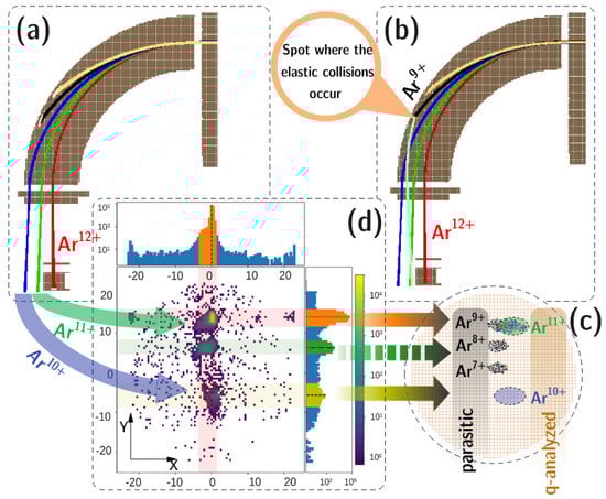
Figure 3.
A comparison of SIMION simulations (a–c) and experiment (d) for the case of Ar recorded by the Faraday Cup (a) with the trajectories of Ar and Ar ions alone; (b) with the trajectory of the Ar beam suffering an elastic collision; (c) peaks expected on the 2D detector.
One can also notice a third peak between the Ar and Ar peaks. Moreover on the x-axis projection, we notice an asymmetry of the peak originating from additional “parasitic” peaks. With SIMION, we simulate the possibility that the Ar beam that hits the outer curved electrode undergoes an elastic-type collision [11,12] and that during this phenomenon Ar, Ar and Ar ions could be produced. Those parasitic beams are then driven towards the detector. Simulations are carried out with the hypothesis of a mirror reflection on the outer electrode surface with no kinetic energy loss. The results (Figure 3) demonstrate that the Ar peak could be composed of both Ar and Ar ions, and that the third peak could be parasitic Ar ions. We note that, among the different charge states formed by electron capture from the residual gas, this measurement only aims at detecting the 11+ and 10+ charge states.
4. Discussion and Conclusions
We present here a home-made ion spectrometer that has been tested at ARIBE. Its design produced satisfactory results in terms of charge state separation in agreement with the ion trajectory simulations carried out. These first tests allow us to evaluate different background contributions. To lower or even remove their contribution, we propose to slightly evolve the design of our spectrometer. In this second version, a grid polarized to about 100 V will be placed in front of the MCP detector to reduce the uniform background. In order to avoid as much as possible the background from the potential elastic scattering of ions, a large rectangular opening has been machined in the outer electrode of the spectrometer. This opening could be covered by a stainless steel grid with 90% transmission as shown in Figure 4. In addition, we plan to improve the pressure inside the spectrometer with a direct pumping of the spectrometer itself. This will reduce the tail (see Figure 2) and the uniform background. This configuration will be tested at ARIBE in the forthcoming months, using the same conditions as the tests reported in this paper.
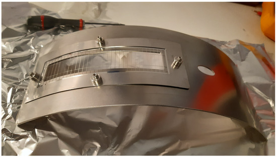
Figure 4.
The rectangular hole and grid on the outer curved electrodes of the second version of the spectrometer.
Author Contributions
Conceptualization, A.M., S.M., J.-M.R., J.R. and S.S.; Data curation, M.J. and E.L.; Formal analysis, M.J. and S.V.; Investigation, C.P. and J.R.; Methodology, M.J., A.M., C.P., D.S., S.S. and M.T.; Project administration, E.L., A.B.-D., J.-Y.C., A.G., M.L., U.S. and T.S.; Resources, A.M., J.-Y.C., J.R. and P.R.; Software, S.M.; Supervision, E.L. and C.P.; Writing—original draft, M.J.; Writing—review and editing, M.J., E.L., A.M., C.P., M.T. and D.V. All authors have read and agreed to the published version of the manuscript.
Funding
The doctoral contract of Mariette Jolly is funded by Sorbonne Université in the framework of the Initiative Physique des Infinis (IDEX SUPER). Part of the equipment is financed by the PLAS@PAR Research Federation. We kindly acknowledge funding by ANR under Project No.ANR-13-IS04-0007.
Data Availability Statement
Not applicable.
Conflicts of Interest
The authors declare no conflict of interest.
References
- Aumayr, F.; Ueda, K.; Sokell, E.; Schippers, S.; Sadeghpour, H.; Merkt, F.; Gallagher, T.F.; Dunning, F.B.; Scheier, P.; Echt, O.; et al. Roadmap on photonic, electronic and atomic collision physics: III. Heavy particles: With zero to relativistic speeds. J. Phys. B At. Mol. Opt. Phys. 2019, 52, 171003. [Google Scholar] [CrossRef]
- Lestinsky, M.; Andrianov, V.; Aur, B.; Bagnoud, V.; Bernhardt, D.; Beyer, H.; Bishop, S.; Blaum, K.; Bleile, A.; Borovik, A.; et al. Physics book: CRYRING@ESR. Eur. Phys. J. Spec. Top. 2016, 225, 797–882. [Google Scholar] [CrossRef]
- Bernigaud, V.; Kamalou, O.; Lawicki, A.; Capron, M.; Maisonny, R.; Manil, B.; Maunoury, L.; Rangama, J.; Rousseau, P.; Chesnel, J.Y.; et al. ARIBE: A low energy ion beam facility in Caen. Publ. l’Observatoire Astron. Beogr. 2008, 84, 83–86. [Google Scholar]
- SIMION 3D Suite. Available online: https://simion.com/ (accessed on 15 September 2022).
- Yavor, M. Chapter 6 Electrostatic Energy Analyzers. In Optics of Charged Particle Analyzers, Advances in Imaging and Electron Physics; Elsevier: Amsterdam, The Netherlands, 2009; Volume 157, pp. 213–258. [Google Scholar] [CrossRef]
- Matsuda, H. Electrostatic analyzer with variable focal length. J. Mass Spectrom. Soc. Jpn. 1961, 9, 8–14. [Google Scholar] [CrossRef]
- Wiza, J.L. Microchannel plate detectors. Nucl. Instrum. Methods 1979, 162, 587–601. [Google Scholar] [CrossRef]
- Schury, D.; Kumar, A.; Mery, A.; Chesnel, J.Y.; Levy, A.; Mace, S.; Prigent, C.; Ramillon, J.M.; Rangama, J.; Rousseau, P.; et al. An electrostatic in-line charge-state purification system for multicharged ions in the kiloelectronvolt energy range. Rev. Sci. Instrum. 2019, 90, 083306. [Google Scholar] [CrossRef] [PubMed]
- Caen, L. Fast Acquisition System for Nuclear Research. Available online: http://faster.in2p3.fr (accessed on 15 September 2022).
- Dahl, D.A. SIMION for the personal computer in reflection. Int. J. Mass Spectrom. 2000, 200, 3–25. [Google Scholar] [CrossRef]
- Van der Weg, W.; Bierman, D. Collisions of Ar+ ions with surface Cu atoms and charge exchange of scattered ions near the metal surface. Physica 1969, 44, 177–205. [Google Scholar] [CrossRef]
- Winter, H. Collisions of atoms and ions with surfaces under grazing incidence. Phys. Rep. 2002, 367, 387–582. [Google Scholar] [CrossRef]
Publisher’s Note: MDPI stays neutral with regard to jurisdictional claims in published maps and institutional affiliations. |
© 2022 by the authors. Licensee MDPI, Basel, Switzerland. This article is an open access article distributed under the terms and conditions of the Creative Commons Attribution (CC BY) license (https://creativecommons.org/licenses/by/4.0/).