Abstract
Recently, we proposed the spin-selective coherent electron transfer in a silicon-quantum-dot array. It requires temporal tuning of two pulses of an oscillating magnetic field and gate voltage control. This paper proposes a simpler method that requires a single pulse of oscillating magnetic field and gate voltage control. We examined the robustness of the control against the error in the pulse amplitude and the effect of the excited states relaxation to the control efficiency. In addition, we propose a novel control method based on a shortcuts-to-adiabaticity protocol, which utilizes two pulses but requires temporal control of the pulse amplitude for only one of them. We compared their efficiencies under the effect of realistic pulse amplitude errors and relaxation.
1. Introduction
Spins in silicon-based quantum dots are a promising candidate for fault-tolerant quantum information processing (QIP) [1]. Readout and single-qubit gate control fidelities above the surface code threshold [2] have been experimentally demonstrated by taking advantage of exceptionally long longitudinal relaxation times [3,4,5] and transverse relaxation times [6,7,8,9]. These are two figures of merit that are highly desirable for a scalable quantum computer. High fidelity spin readout has been demonstrated in a CMOS device by its robustness with respect to temperature [10]. Recently, high-fidelity single qubit operations above 1 K have also been demonstrated, potentially reducing large-scale quantum processor design constraints [11]. It is known that all single-qubit gates, and one of two-qubit gates that entangles two qubits, such as the CNOT gate, form the universal set of gates. Entenglement can be introduced only by a non-local operation, such as the one introduced in [12]. Several types of quantum gate operations, including two-qubit quantum gates, have been demonstrated [13,14,15] by employing the exchange interaction between single spins in isotopically enriched silicon [16]. Furthermore, single electron pumps [17,18,19,20,21,22,23] and shuttling of single electron [24,25] in quantum dot array have been also demonstrated at the level of metrological accuracy. The coherent spin displacement of individual electrons has been demonstrated in a GaAs system quantum dot array [26].
Inspired by a theoretical analysis of two-qubit gate implementation employing state-dependent potentials in cold atom systems in optical fiber array [27,28,29], we recently proposed a spin-selective electron transfer method described in [12], which realizes non-local qubit operations in a quantum dot array. This proposal also offers quantum non-demolition measurement of electron spin [30,31,32] provided that the electron position is measured without introducing the dissipation to the electron. Quantum non-demolition measurements can be used for improvement of qubit operations. In our previous method, temporal tuning of two pulses of an oscillating magnetic field was required.
In this paper, we report a simplified and improved method of spin-selective coherent electron transfer in a silicon-quantum-dot array driven by a single pulse of oscillating magnetic field and gate voltage control. We examine the robustness of the control against the pulse amplitude error and the effect of the relaxation to control efficiency. We also propose a method based on the shortcut-to-adiabaticity (STA) protocol, which utilizes two pulses but requires temporal control of one of the pulses only.
We present the framework of the spin-selective electron transfer with a single -pulse in Section 2, and the adiabatic and the shortcuts-to-adiabaticity controls in Section 3. In Section 4, we compare the robustness of the controls against the pulse amplitude error, the relaxation of excited states and the dephasing of a spin.
2. Spin-Selective Electron Transfer with a Single -Pulse
Figure 1a schematically shows the system under consideration, where two-dimensional electron gas is in the -plane. A stretched quantum dot (Dot 0) is located along the z-axis. We assume that the confinement of the electron in the y direction is at least twice tighter than the confinement in the z direction. Thus, the one-dimensional model can approximate a few of the lowest-energy eigenstates of the dot that we utilize. There is a time-independent uniform magnetic field along the z-axis. A conducting lead (blue line) carries the AC current, , which produces the pump magnetic field along the x-axis perpendicular to the two-dimensional electron gas. The conducting lead is separated from the center of Dot 0 by distance , and is tilted with respect to the z-axis by angle to introduce the spatial inhomogeneity of in Dot 0 [12], which is essential for our proposal, as shown in Equation (4). We assume that the initial condition of the electron trapped in Dot 0 is a superposition of the spin-up ground state and the spin-down ground state. The squared amplitudes of the wave functions of the three low-lying eigenstates for either spin-up or spin-down are shown in Figure 1b.
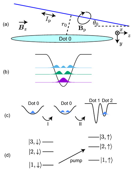
Figure 1.
(a) Proposed system. The blue line represents the conducting lead carrying the AC control current producing the magnetic field (pump field) perpendicular to the surface. The conducting lead is tilted with respect to the z-axis by angle . Here, is the distance of the lead from the center of Dot 0. The generated AC magnetic field couples the ground state and the first excited state in the dot. (b) Colors show the square of the amplitude of the wave functions of the three lowest eigenstates with either spin-up or spin-down in Dot 0. The black curve is the schematic of the potential of Dot 0. (c) Schematics of the spin-selective electron transfer. The black curves depict the potential profile of quantum dot(s) at each step. The blue color represents the squared amplitude of the wave function of an electron whose initial spin was down. (d) Energy diagram of the system in Step I. Here, is the ith instantaneous eigenstate of Dot 0 with spin-up (down). The pump field couples and .
Our spin-selective electron transfer protocol is illustrated in Figure 1c. The protocol is composed of two steps. In Step I the lowest energy spin-down state is transferred to the first spin-up excited state, while the lowest energy spin-up state is left unchanged. In Step II the center potential barrier is adiabatically raised to split Dot 0 into two potential wells: Dot 1 and Dot 2. The depths of the potential wells are tuned so that the bottom of the potential of Dot 2 becomes above that of Dot 1. As the potential is modified, the wave function of the first spin-up excited state is carried into Dot 2 because the wave function of the instantaneous first excited eigenstate with spin-up is mostly located in Dot 2. The wave function of the lowest energy spin-up state is loaded into Dot 1. Two states are individually accessible after the wave function is separated into two Dots. Thus, it can be used for non-local multi-qubit operation when this scheme is applied to a multi-electron system [12].
Previously, we used another separate dot (Dot 4 in [12]) for Step I to avoid the possible fluctuation of the separation of the energy levels, which may be caused by the fluctuation of the gate voltages of the dots [12]. However, in this paper we do not employ such a separate dot in order to make the scheme simpler by assuming that the fluctuation of the gate voltages is negligible.
2.1. Step I
The electron is initially confined in Dot 0. We use the energy eigenstates of Dot 0 with as the basis vectors of the system to explain the schemes of Step I. Figure 1d depicts the energy diagram of Dot 0. Here, for and 3 denotes the first three low-lying energy levels with spin-down (up) along the z direction. The separations of the adjacent energy eigenvalues are nonuniform due to the anharmonicity of the potential of the dot. The stationary magnetic field causes the Zeeman splitting with energy difference between the spin-up and down states, where g is the electron g-factor and is the Bohr magneton.
We aim at a spin-selective state transfer in which only the lowest energy spin-down electron is transferred from to , while the lowest energy spin-up electron remains unaffected. The frequency of the pump field is adjusted to , where is the energy eigenvalue of , so that couples and . Note that is not coupled to any states by . A typical value of was calculated as 47 GHz in [12].
We consider the dynamics of a state which is in at the initial time. The effective Hamiltonian of the system is written in terms of the subset of the states as a basis. The pulsed pump field employed in Step I is represented as
with the envelope function of the pump field at the center of Dot 0. The function is defined as the ratio of the intensity of the field at to . In other words, characterizes the spatial dependence of the pump magnetic field. The Hamiltonian of the two-level system can be written, by using the rotating frame and the rotating wave approximation (RWA), as
with the Rabi frequency given by
and the overlapping factor defined by
where (see Appendix A of [12] for the derivation of ). If the pump magnetic field were spatially uniform, would vanish because of the orthogonality of the energy eigenvectors with different eigenvalues and no coupling between the two eigenstates would be introduced. Thus, the nonuniformity of the magnetic field is essential to couple the energy eigenstates.
We take the envelope function as
where is the rectangular pulse height and is the pulse width, which defines the duration of Step I. When the pulse area is , that is,
the state is transferred from to under the action of the pump pulse. Typical dynamics of the system are shown for in Figure 2.
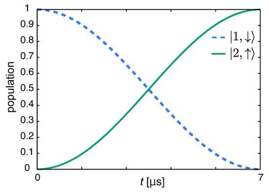
Figure 2.
Time dependence of the populations for , mT and s.
2.2. Step II
As the middle potential barrier, which divides Dot 0 into Dot 1 and Dot 2, is raised, and the potential depth of Dot 2 is tuned, the wave functions of the ground and the first excited states are transferred into Dot 1 and Dot 2, respectively. We use the one-dimensional model with the rectangular potentials illustrated in Figure 3a to simulate Step II. The potentials for dots are approximated by the rectangular ones for simplicity. Details of the potential profile do not affect the result because this step employs adiabatic dynamics. for and for denote the barrier heights and the potential depths of the dots, respectively. The widths of the dots and the widths of the barriers are all taken as 30 nm. At the initial time () of Step II, we take so that the two dots are combined to form a single larger dot (Dot 0). The middle barrier height and the dot potential depth are adiabatically ramped from 0 to and , respectively, as
with and , while the other parameters are kept constant; and , where is the time required for Step II. R interpolates between 0 and 1 smoothly with , and , where prime denotes the time derivative. Figure 3b depicts the time-evolution of the squared amplitude of the wave function whose initial state was , the spin-up ground state in Dot 0 with ns. The wave function is transferred to Dot 1 and is mostly localized within Dot 1 at . Figure 3c depicts the time-evolution of the squared amplitude of the wave function with the initial state . The wave function is transferred to Dot 2 and is mostly localized within Dot 2 at . The fidelity of Step II, defined by the overlap between the state at and the target energy eigenstate, is more than 0.9999 for ns. This shows that undesirable non-adiabatic transitions are safely negligible.
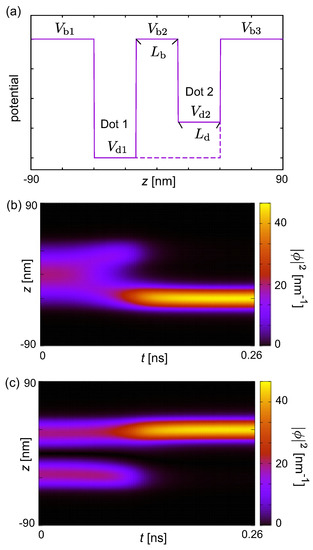
Figure 3.
(a) Schematics of Dot 1 and Dot 2 in a one-dimensional model. and are the heights of the potential barriers and the depths of the potential wells, respectively. In this panel the difference in is exaggerated for purpose of illustration. The dashed line shows the potential profile at . The time-evolution of the squared amplitude of the wave functions with initial states (b) and (c). The parameter set used was nm, , eV and meV.
3. Adiabatic and Shortcuts-To-Adiabaticity Controls
In this paper, we propose new improved protocols for Step I, which involves three states; namely, and of Dot 0. The pump field couples and while the Stokes field couples and . In contrast with the previous study [12], the envelope function of the Stokes field is kept constant in this work. Thus, the time-dependent tuning is required only for the pump field.
The schematic of our protocol is illustrated in Figure 4a. In Step I the lowest-energy spin-down state is transferred to the spin-down second excited state, while the lowest-energy spin-up state is left unaffected. Figure 4b shows the energy diagram relevant to Step I. In Step II the potential barriers are adiabatically raised to split Dot 0 to three potential wells: Dots 1, 2 and 3. The depths of the potential wells are tuned so that Dot 1 and Dot 3 have the lowest and the highest potential minima, respectively. The wave function of the second spin-down excited state is carried into Dot 3 because the wave function of the instantaneous second excited eigenstate with spin-down is located in Dot 3. On the other hand, the wave function of the lowest energy spin-up state is loaded to Dot 1. In the following, we mainly discuss Step I. See [12] for the numerical simulation for Step II.
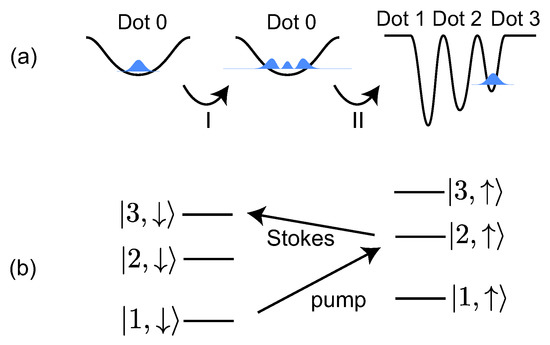
Figure 4.
(a) Schematic description of the spin-selective single electron transfer. The black curves show the potential profiles of the quantum dot(s). The blue color represents the squared amplitude of the wave function of an electron whose initial spin was down. (b) Energy diagram of the system in Step I. The AC magnetic field (pump field) couples and , while (Stokes field) couples and .
We consider the dynamics of the state which is initially . A subset of states, , is used as the basis. We employ the rotating frame and the RWA to rewrite the Hamiltonian of the three-level system in the form
with the Rabi frequencies in Equation (3) and given by
and the overlapping factors defined by
We use in this study. (See Appendix A of [12] for the derivation of ). We assume that and in Equation (8) can be controlled individually using two tone pulses. Typical frequencies of the pump and the Stokes fields are 47 GHz and 32 GHz, respectively [12].
3.1. Spin-Selective STIRAP with Constant
We examine a protocol with a linearly increased pump field having recourse to the adiabatic dynamics of the system. The protocol is called stimulated Raman adiabatic passage (STIRAP) [33,34,35]. STIRAP has been widely studied for adiabatic transport of electrons [36,37], single atoms [38,39,40,41,42,43] and BECs [44,45,46,47], and population transfer of molecules [48,49,50,51,52,53,54,55]. It has already been demonstrated in various areas, such as control of a superconducting qubit [56], chemical reaction dynamics [57], laser-induced cooling of atomic gases [58], light beams propagating in three evanescently-coupled optical waveguides [59,60,61,62] and sound propagation in sonic crystals [63]. This protocol can be applied to transfer qubits coherently over long distance in spin-based quantum computing architecture [64].
The envelope functions of the pump and the Stokes fields for are given by
A time-dependent, field-dressed eigenstate of the system is represented as
where is given by
We assume that the initial state is which is equivalent to because at the initial time. The quantum adiabatic theorem states that if are changed slowly enough and the initial state is an eigenstate , the state remains in the same eigenstate during the control. Therefore, when increases sufficiently slowly, the population is gradually transferred from to [34,35]. We take so that at the final time. For , and are to be gradually decreased to zero. The population of each state () is approximately unchanged if the duration of this process is long enough and because the state remains in .
Figure 5 shows the time dependence of the envelope functions and (Figure 5a,b) and the corresponding time dependence of the population of each state (Figure 5c,d). We use mT and mT so that the maximum value of is the same as the one used in -pulse control and at . In the control with s, the state deviates from due to unwanted nonadiabatic population transfer. Thus, the population of at is less than 0.5. On the other hand, the dynamics are approximated by , and the population of is approximately 0.95 at for s. However, required for the adiabatic dynamics is too long, in which case the efficiency will be degraded by relaxation and decoherence in actual experiments.
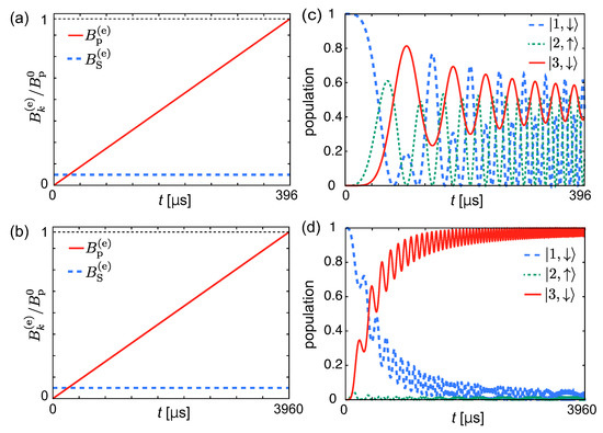
Figure 5.
Envelope functions for normalized by for STIRAP with (a) s and (b) s. is the maximum amplitude of the pump field. The thin dotted line represents 1. Panels (c,d) are for the time dependencies of the populations corresponding to the envelope functions in the left panels.
3.2. Shortcuts to Adiabaticity
Shortcuts-to-adiabaticity (STA) protocols or assisted adiabatic transformations have been developed to reach the same target state as reference adiabatic dynamics starting from the given initial state, with overall weaker driving fields and/or shorter durations [65,66]. The STA protocols have been utilized for manipulations of, e.g., spin systems [67,68,69,70,71], electron spin of a single nitrogen-vacancy center in diamond [72,73], isolated atoms and molecules [74,75,76,77,78] and Bose-Einstein condensates [79,80,81,82,83,84,85,86,87,88]. Several STA protocols have been already demonstrated with STIRAP systems; for example, Loop STIRAP [89], counter-diabatic [74,75], fast-forward [90] and invariant-based engineering protocols [75,91].
We show the way to derive which approximately generates in shorter time than that required for the adiabatic dynamics in Section 3.1 using the invariant based engineering protocol [75]. It is known that the state of the form
is a solution of the Schrödinger equation when
These equations can be rewritten as
We use defined by
where and are constant parameters to be chosen so that
It is seen from Equation (14) that if and , and that if and . Thus, we set to be small, and set . is obtained by integrating Equation (16) using Equations (15) and (17). is optimized so that . Therefore, determined by Equations (3) and (15) can drive the initial state approximately to the target state up to an overall phase.
Typical time dependencies of and the population of each state are shown in Figure 6 for various . The values of and are chosen so that the maximum value of is the same as the one used in the -pulse control. It is seen that population of is small for s. On the other hand, the population of is sizable around for and 132s in contrast to the adiabatic dynamics analyzed in Section 3.1.
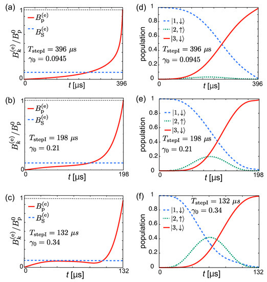
Figure 6.
Envelope functions for normalized by for the invariant-based engineering protocol with (a) s, and ; (b) s, and ; and (c) s, and . is the maximum amplitude of the pump field. The thin dotted line represents 1. (d)–(f) Time dependencies of the populations corresponding to the envelope functions in the left panels.
For , and are to be gradually decreased to zero. The population of each state is approximately unchanged under this. This process is insensitive to the details of and as long as , and the duration of the process is much shorter than . Therefore, the duration of this process is negligible (see Appendix A).
4. Robustness of Control
Robustness of the control against the pulse amplitude error, the effect of the relaxation of excited states and the effect of the dephasing of spin to the control efficiency are examined in this section.
4.1. The Effect of the Error of the Pulse Amplitude
We multiply the pump field by to analyze the robustness of the control against the pulse amplitude error. The fidelities of the -pulse control and the invariant-based engineering protocol are defined by the population of and the population of at , respectively. Figure 7 shows the fidelity as a function of for the -pulse control and the invariant-based engineering protocol. It is seen that the fidelity of the latter is higher than the one of the former in a wide range of values, while the maximum value of the fidelity for the former is higher than the one of the latter. This shows that the invariant-based engineering protocol is robust against the pulse amplitude error compared to the -pulse control.
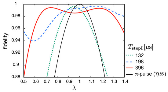
Figure 7.
Dependence of the fidelity at on for the -pulse and the invariant-based engineering protocols. is the multiplicative factor of amplitude error, where corresponds to no error.
4.2. The Effect of the Relaxation of Excited States
We examine the effect of the relaxation of excited states using the master equation [92]:
where is the density operator. is given by
with the relaxation rate , where is the annihilation operator represented as
corresponds to spin-down (up) state. We neglect the effect of spin relaxation assuming that the relaxation rate of excited states is much faster than the spin relaxation rate. The effect of the spin dephasing effect is studied in the next subsection.
Figure 8 shows the fidelity of the -pulse control and the invariant-based engineering protocol as a function of . It is seen that the -pulse control is much more robust against the relaxation than the invariant-based engineering protocol because its control duration is much shorter than the one for the invariant-based engineering protocol.
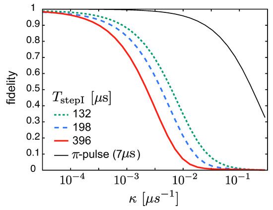
Figure 8.
Dependence of the fidelity at on for the -pulse and the invariant-based engineering protocols.
4.3. Effect of Dephasing of Spin
We examine the effect of the dephasing of spin using the master Equation [92]:
where is given by
with the dephasing rate . We neglect the effect of the other relaxations.
We assume that the initial state is a superposition of spin up and down states represented as
The target states for the -pulse control and the invariant-based engineering protocol are represented as
and
respectively. Note that the state is transferred to in the -pulse case without decoherence. On the other hand, the state is transferred to in the invariant-based engineering protocol if there is no decoherence. The phases of in Equation (26) and in Equation (27) appear after the controls without decoherence. We define the fidelity, F, of the controls as
and define the coherence, C, at for the -pulse control as
We define the coherence for the invariant-based engineering protocol as
Figure 9a shows the dependence of the fidelity of the the -pulse and the invariant-based engineering protocols on . It is seen that the fidelity decreases with the increase of . Crossings of the fidelity of the invariant-based engineering protocols are observed when increases. Although we could not have a clear reason for this, we found that the main contribution to the fidelity came from the diagonal elements of the density matrix, and the off-diagonal elements were approximately vanishing in that parameter region. Figure 9b shows the dependence of the coherence of the the -pulse and the invariant-based engineering protocols on . The coherence decreases as increases. The fidelity and coherence of the -pulse control is higher than the invariant-based engineering protocol because of the short control time. Increasing the amplitude of the oscillating magnetic field can shorten the control time, leading to improvement of the control fidelity.
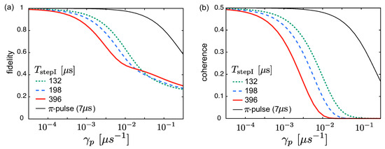
Figure 9.
Dependence of the fidelity (a) and the coherence (b) at on for the -pulse and the invariant-based engineering protocols.
5. Conclusions
In the research presented, we studied spin-selective coherent electron transfer in a quantum dot array with time-dependent tuning of the driving field. The electron is excited and transferred into different quantum dots (Dots 1 and 2 in Figure 1c) depending on the initial electron spin. We have proposed two different methods: the -pulse control and the invariant-based engineering protocol. The -pulse control offers fast transport, while a robust control against the error of the pulse area of the control field is achieved by the invariant-based engineering protocol, although the manipulation time is longer than that of the -pulse control. We also studied the effect of the relaxation of excited states and the dephasing of spin to the control efficiency. The -pulse control offers robustness against the relaxation of excited states due to its short control time, while the invariant-based engineering protocol is sensitive to the relaxation and the dephasing rates.
In Section 3 we studied the effective three-level-system where the constant coupling between states and is caused by an external field. We emphasize that the control developed with constant can also be applied to systems where two degenerate energy levels have an intrinsic fixed coupling. Such a condition can be realized, e.g., in a cavity QED system where an atom is coupled to a resonant cavity mode [93], and in a circuit QED system where an artificial atom is coupled to a tunable resonator mode [94,95].
In our scheme, a combined quantum dot (Dot 0) is used. It is known that making the dot size large is difficult in silicon, where the electron wave function needs to be tightly confined. In that sense the -pulse control is better than the invariant-based engineering protocol, because the former one utilizes only up to the first excited state which is less spread-out than the second excited state. The smaller dot size requires the larger frequency of the AC magnetic field in our scheme. Thus, the size of the dot is limited by the experimental feasibility of the frequency of the AC magnetic field. On the other hand, the GaAs system can form a large dot, although the short coherence time is problematic [96]. The spin-orbit coupling [97,98] could be problematic in Step II. However, we believe that the study of clever pulse schemes to mitigate spin-orbit coupling is beyond the scope of the paper. This will indeed be something of interest for further investigation.
Author Contributions
S.M. developed and analyzed the model. K.Y.T. and M.N. contributed to the development of the model and data analysis. All authors commented on and edited the manuscript of which the original draft was written by S.M. All authors have read and agreed to the published version of the manuscript.
Funding
S.M. acknowledges the support from JST ERATO (grant number JPMJER1601) and JSPS KAKENHI (grant number 18K03486). K.Y.T. acknowledges the support from the Academy of Finland (grant numbers 308161, 314302 and 316551).
Conflicts of Interest
The authors declare no conflict of interest.
Abbreviations
The following abbreviations are used in this manuscript:
| STIRAP | stimulated Raman adiabatic passage |
| STA | shortcuts to adiabaticity |
| RWA | rotating wave approximation |
Appendix A. End of Step I
For , and are gradually decreased to zero. To simulate this process, we assume
where characterizes the decay time of the envelope functions. and start to decrease at and , respectively.
Figure A1a–c show the envelope functions and for the invariant-based engineering protocol with s and s. The time dependence of the envelope functions for are the same as the ones in Figure 6b,c. Figure A1d–f show that the populations are almost unchanged for , while and are decreased. This process is insensitive to , and the duration of the process can be much shorter than .

Figure A1.
Envelope functions for normalized by for the invariant-based engineering protocol with (a) s, , and s; (b) s, , and s; (c) s, , and s. is the maximum amplitude of the pump field. The thin dotted line represents 1. (d)–(f) Time dependence of the eigenstate populations corresponding to the envelopes in the left panels.

References
- Loss, D.; DiVincenzo, D.P. Quantum computation with quantum dots. Phys. Rev. A 1998, 57, 120–126. [Google Scholar] [CrossRef]
- Fowler, A.G.; Mariantoni, M.; Martinis, J.M.; Cleland, A.N. Surface codes: Towards practical large-scale quantum computation. Phys. Rev. A 2012, 86, 032324–032371. [Google Scholar] [CrossRef]
- Morello, A.; Pla, J.J.; Zwanenburg, F.A.; Chan, K.W.; Tan, K.Y.; Huebl, H.; Möttönen, M.; Nugroho, C.D.; Yang, C.; van Donkelaar, J.A.; et al. Single-shot readout of an electron spin in silicon. Nature 2010, 467, 687–691. [Google Scholar] [CrossRef] [PubMed]
- Pla, J.J.; Tan, K.Y.; Dehollain, J.P.; Lim, W.H.; Morton, J.J.L.; Jamieson, D.N.; Dzurak, A.S.; Morello, A. A single-atom electron spin qubit in silicon. Nature 2012, 489, 541–545. [Google Scholar] [CrossRef] [PubMed]
- Muhonen, J.T.; Dehollain, J.P.; Laucht, A.; Hudson, F.E.; Kalra, R.; Sekiguchi, T.; Itoh, K.M.; Jamieson, D.N.; McCallum, J.C.; Dzurak, A.S.; et al. Storing quantum information for 30 seconds in a nanoelectronic device. Nat. Nanotech. 2014, 9, 986–991. [Google Scholar] [CrossRef] [PubMed]
- Maune, B.M.; Borselli, M.G.; Huang, B.; Ladd, T.D.; Deelman, P.W.; Holabird, K.S.; Kiselev, A.A.; Alvarado-Rodriguez, I.; Ross, R.S.; Schmitz, A.E.; et al. Coherent singlet-triplet oscillations in a silicon-based double quantum dot. Nature 2012, 481, 344–347. [Google Scholar] [CrossRef]
- Veldhorst, M.; Hwang, J.C.C.; Yang, C.H.; Leenstra, A.W.; de Ronde, B.; Dehollain, J.P.; Muhonen, J.T.; Hudson, F.E.; Itoh, K.M.; Morello, A.; et al. An addressable quantum dot qubit with fault-tolerant control-fidelity. Nat. Nanotechnol. 2014, 9, 981–985. [Google Scholar] [CrossRef]
- Kawakami, E.; Scarlino, P.; Ward, D.R.; Braakman, F.R.; Savage, D.E.; Lagally, M.G.; Friesen, M.; Coppersmith, S.N.; Eriksson, M.A.; Vandersypen, L.M.K. Electrical control of a long-lived spin qubit in a Si/SiGe quantum dot. Nat. Nanotechnol. 2014, 9, 666–670. [Google Scholar] [CrossRef]
- Itoh, K.M.; Watanabe, H. Isotope engineering of silicon and diamond for quantum computing and sensing applications. MRS Commun. 2014, 4, 143–157. [Google Scholar] [CrossRef]
- Urdampilleta, M.; Niegemann, D.J.; Chanrion, E.; Jadot, B.; Spence, C.; Mortemousque, P.; Bäuerle, C.; Hutin, L.; Bertrand, B.; Barraud, S.; et al. Gate-based high fidelity spin readout in a CMOS device. Nat. Nanotechnol. 2019, 14, 737–741. [Google Scholar] [CrossRef]
- Yang, C.H.; Leon, R.C.C.; Hwang, J.C.C.; Saraiva, A.; Tanttu, T.; Huang, W.; Lemyre, J.C.; Chan, K.W.; Tan, K.Y.; Hudson, F.E.; et al. Silicon quantum processor unit cell operation above one Kelvin. arXiv 2019, arXiv:1902.09126. [Google Scholar]
- Masuda, S.; Tan, K.Y.; Nakahara, M. Spin-selective electron transfer in a quantum dot array. Phys. Rev. B 2018, 97, 045418–045431. [Google Scholar] [CrossRef]
- Noiri, A.; Yoneda, J.; Nakajima, T.; Otsuka, T.; Delbecq, M.R.; Takeda, K.; Amaha, S.; Allison, G.; Ludwig, A.; Wieck, A.D.; et al. Coherent electron-spin-resonance manipulation of three individual spins in a triple quantum dot. Appl. Phys. Lett. 2016, 108, 153101–153105. [Google Scholar] [CrossRef]
- Takeda, K.; Kamioka, J.; Otsuka, T.; Yoneda, J.; Nakajima, T.; Delbecq, M.R.; Amaha, S.; Allison, G.; Kodera, T.; Oda, S.; et al. A fault-tolerant addressable spin qubit in a natural silicon quantum dot. Sci. Adv. 2016, 2, e1600694–e1600699. [Google Scholar] [CrossRef] [PubMed]
- Harvey-Collard, P.; Tobias Jacobson, N.; Rudolph, M.; Dominguez, J.; Ten Eyck, G.A.; Wendt, J.R.; Pluym, T.; King Gamble, J.; Lilly, M.P.; Pioro-Ladriére, M.; et al. Coherent coupling between a quantum dot and a donor in silicon. Nat. Commun. 2017, 8, 1029–1034. [Google Scholar] [CrossRef]
- Veldhorst, M.; Yang, C.H.; Hwang, J.C.C.; Huang, W.; Dehollain, J.P.; Muhonen, J.T.; Simmons, S.; Laucht, A.; Hudson, F.E.; Itoh, K.M.; et al. A two-qubit logic gate in silicon. Nature 2015, 526, 410–414. [Google Scholar] [CrossRef]
- Kouwenhoven, L.P.; Johnson, A.T.; van der Vaart, N.C.; Harmans, C.J.P.M.; Foxon, C.T. Quantized current in a quantum-dot turnstile using oscillating tunnel barriers. Phys. Rev. Lett. 1991, 67, 1626–1629. [Google Scholar] [CrossRef]
- Blumenthal, M.D.; Kaestner, B.; Li, L.; Giblin, S.; Janssen, T.J.B.M.; Pepper, M.; Anderson, D.; Jones, G.; Ritchie, D.A. Gigahertz quantized charge pumping. Nat. Phys. 2007, 3, 343–347. [Google Scholar] [CrossRef]
- Jehl, X.; Voisin, B.; Charron, T.; Clapera, P.; Ray, S.; Roche, B.; Sanquer, M.; Djordjevic, S.; Devoille, L.; Wacquez, R.; et al. Hybrid Metal-Semiconductor Electron Pump for Quantum Metrology. Phys. Rev. X 2013, 3, 021012–021023. [Google Scholar] [CrossRef]
- Connolly, M.R.; Chiu, K.L.; Giblin, S.P.; Kataoka, M.; Fletcher, J.D. Chua, C.; Griffiths, J.P.; Jones, G.A.C.; Fal’ko, V.I.; Smith C.G.; et al. Gigahertz quantized charge pumping in graphene quantum dots. Nat. Nanotechnol. 2013, 8, 417–420. [Google Scholar] [CrossRef]
- Rossi, A.; Tanttu, T.; Tan, K.Y.; Iisakka, I.; Zhao, R.; Chan, K.W.; Tettamanzi, G.C.; Rogge, S.; Dzurak, A.S.; Möttönen, M. An Accurate Single-Electron Pump Based on a Highly Tunable Silicon Quantum Dot. Nano Lett. 2014, 14, 3405–3411. [Google Scholar] [CrossRef] [PubMed]
- Pekola, J.; Saira, O.-P.; Maisi, V.F.; Kemppinen, A.; Möttönen, M.; Pashkin, Y.A.; Averin, D.V. Single-electron current sources: Toward a refined definition of the ampere. Rev. Mod. Phys. 2013, 86, 1421–1472. [Google Scholar] [CrossRef]
- Tanttu, T.; Rossi, A.; Tan, K.Y.; Huhtinen, K.-E.; Chan, K.W.; Möttönen, M.; Dzurak, A.S. Electron counting in a silicon single-electron pump. New J. Phys. 2015, 17, 103030–103035. [Google Scholar] [CrossRef]
- Chan, K.W.; Möttönen, M.; Kemppinen, A.; Lai, N.S.; Tan, K.Y.; Lim, W.H.; Dzurak, A.S. Single-electron shuttle based on a silicon quantum dot. Appl. Phys. Lett. 2011, 98, 212103–212105. [Google Scholar] [CrossRef]
- Baart, T.A.; Shafiei, M.; Fujita, T.; Reichl, C.; Wegscheider, W.; Vandersypen, L.M.K. Single-spin CCD. Nat. Nanotechnol. 2016, 11, 330–334. [Google Scholar] [CrossRef] [PubMed]
- Flentje, H.; Mortemousque, P.-A.; Thalineau, R.; Ludwig, A.; Wieck, A.D.; Bäuerle, C.; Meunier, T. Coherent long-distance displacement of individual electron spins. Nat. Commun. 2017, 8, 501. [Google Scholar] [CrossRef] [PubMed]
- Jaksch, D.; Briegel, H.-J.; Cirac, J.I.; Gardiner, C.W.; Zoller, P. Entanglement of Atoms via Cold Controlled Collisions. Phys. Rev. Lett. 1999, 82, 1975–1978. [Google Scholar] [CrossRef]
- Lapasar, E.H.; Kasamatsu, K.; Kondo, Y.; Nakahara, M.; Ohmi, T. Scalable Neutral Atom Quantum Computer with Interaction on Demand: Proposal for Selective Application of Two-Qubit Gate. J. Phys. Soc. Jpn. 2011, 80, 114003–114012. [Google Scholar] [CrossRef]
- Lapasar, E.H.; Kasamatsu, K.; Nic Chormaic, S.; Takui, T.; Kondo, Y.; Nakahara, M.; Ohmi, T. Two-Qubit Gate Operation on Selected Nearest-Neighbor Neutral Atom Qubits. J. Phys. Soc. Jpn. 2014, 83, 044005–044010. [Google Scholar] [CrossRef]
- Sarovar, M.; Young, K.C.; Schenkel, T.; Whaley, K.B. Quantum nondemolition measurements of single donor spins in semiconductors. Phys. Rev. B 2008, 78, 245302–245309. [Google Scholar] [CrossRef]
- Puri, S.; McMahon, P.L.; Yamamoto, Y. Single-shot quantum nondemolition measurement of a quantum-dot electron spin using cavity exciton-polaritons. Phys. Rev. B 2014, 90, 155421–155425. [Google Scholar] [CrossRef]
- Nakajima, T.; Noiri, A.; Yoneda, J.; Delbecq, M.R.; Stano, P.; Otsuka, T.; Takeda, K.; Amaha, S.; Allison, G.; Kawasaki, K.; et al. Quantum non-demolition measurement of an electron spin qubit. Nat. Nanotechnol. 2019, 14, 555–560. [Google Scholar] [CrossRef] [PubMed]
- Gaubatz, U.; Rudecki, P.; Schiemann, S.; Bergmann, K. Population transfer between molecular vibrational levels by stimulated Raman scattering with partially overlapping laser fields. A new concept and experimental results. J. Chem. Phys. 1990, 92, 5363–5376. [Google Scholar] [CrossRef]
- Bergmann, K.; Theuer, H.; Shore, B.W. Coherent population transfer among quantum states of atoms and molecules. Rev. Mod. Phys. 1998, 70, 1003–1025. [Google Scholar] [CrossRef]
- Vitanov, N.V.; Halfmann, T.; Shore, B.W.; Bergmann, K. Laser-Induced Population Transfer by Adiabatic Passage Techniques. Ann. Rev. Phys. Chem. 2001, 52, 763–809. [Google Scholar] [CrossRef]
- Greentree, A.D.; Cole, J.H.; Hamilton, A.R.; Hollenberg, L.C.L. Coherent electronic transfer in quantum dot systems using adiabatic passage. Phys. Rev. B 2004, 70, 235317–235322. [Google Scholar] [CrossRef]
- Jong, L.M.; Greentree, A.D.; Conrad, V.I.; Hollenberg, L.C.L.; Jamieson, D.N. Coherent tunneling adiabatic passage with the alternating coupling scheme. Nanotechnology 2009, 20, 405402–405409. [Google Scholar] [CrossRef][Green Version]
- Eckert, K.; Lewenstein, M.; Corbalán, R.; Birkl, G.; Ertmer, W.; Mompart, J. Three-level atom optics via the tunneling interaction. Phys. Rev. A 2004, 70, 023606–023610. [Google Scholar] [CrossRef]
- Eckert, K.; Mompart, J.; Corbalán, R.; Lewenstein, M.; Birkl, G. Three level atom optics in dipole traps and waveguides. Opt. Commun. 2006, 264, 264–270. [Google Scholar] [CrossRef]
- Opatrný, T.; Das, K.K. Conditions for vanishing central-well population in triple-well adiabatic transport. Phys. Rev. A 2009, 79, 012113–012119. [Google Scholar] [CrossRef]
- O’Sullivan, B.; Morrissey, P.; Morgan, T.; Busch, T. Using adiabatic coupling techniques in atom-chip waveguide structures. Phys. Scr. 2010, 140, 014029–014034. [Google Scholar] [CrossRef]
- Morgan, T.; O’Sullivan, B.; Busch, T. Coherent adiabatic transport of atoms in radio-frequency traps. Phys. Rev. A 2011, 83, 053620–053625. [Google Scholar] [CrossRef]
- Morgan, T.; O’Riordan, L.J.; Crowley, N.; O’Sullivan, B.; Busch, T. Coherent transport by adiabatic passage on atom chips. Phys. Rev. A 2013, 88, 053618–053623. [Google Scholar] [CrossRef]
- Graefe, E.M.; Korsch, H.J.; Witthaut, D. Mean-field dynamics of a Bose-Einstein condensate in a time-dependent triple-well trap: Nonlinear eigenstates, Landau-Zener models, and stimulated Raman adiabatic passage. Phys. Rev. A 2006, 73, 013617–013622. [Google Scholar] [CrossRef]
- Rab, M.; Cole, J.H.; Parker, N.G.; Greentree, A.D.; Hollenberg, L.C.L.; Martin, A.M. Spatial coherent transport of interacting dilute Bose gases. Phys. Rev. A 2008, 77, 061602–061605. [Google Scholar] [CrossRef]
- Nesterenko, V.O.; Novikov, A.N.; de Souza Cruz, F.F.; Lapolli, E.L. Tunneling and transport dynamics of trapped Bose-Einstein condensates. Laser Phys. 2009, 19, 616–624. [Google Scholar] [CrossRef]
- Rab, M.; Hayward, A.L.C.; Cole, J.H.; Greentree, A.D.; Martin, A.M. Interferometry using adiabatic passage in dilute-gas Bose-Einstein condensates. Phys. Rev. A 2012, 86, 063605–063614. [Google Scholar] [CrossRef]
- Coulston, G.W.; Bergmann, K. Population transfer by stimulated Raman scattering with delayed pulses: Analytical results for multilevel systems. J. Chem. Phys. 1994, 96, 3467–3475. [Google Scholar] [CrossRef]
- Martin, J.; Shore, B.W.; Bergmann, K. Coherent population transfer in multilevel systems with magnetic sublevels. III. Experimental results. Phys. Rev. A 1996, 54, 1556–1569. [Google Scholar] [CrossRef]
- Halfmann, T.; Bergmann, K. Coherent population transfer and dark resonances in SO2. J. Chem. Phys. 1996, 104, 7068–7072. [Google Scholar] [CrossRef]
- Malinovsky, V.S.; Tannor, D.J. Simple and robust extension of the stimulated Raman adiabatic passage technique to N-level systems. Phys. Rev. A 1997, 56, 4929–4937. [Google Scholar] [CrossRef]
- Kobrak, M.N.; Rice, S.A. Selective photochemistry via adiabatic passage: An extension of stimulated Raman adiabatic passage for degenerate final states. Phys. Rev. A 1998, 57, 2885–2894. [Google Scholar] [CrossRef]
- Kurkal, V.; Rice, S.A. Sequential STIRAP-based control of the HCN→CNH isomerization. Chem. Phys. Lett. 2001, 344, 125–137. [Google Scholar] [CrossRef]
- Cheng, T.; Darmawan, H.; Brown, A. Stimulated Raman adiabatic passage in molecules: The effects of background states. Phys. Rev. A 2007, 75, 013411–013421. [Google Scholar] [CrossRef]
- Jakubetz, W. Limitations of STIRAP-like population transfer in extended systems: The three-level system embedded in a web of background states. J. Chem. Phys. 2012, 137, 224312–224327. [Google Scholar] [CrossRef]
- Kumar, K.S.; Vepsäläinen, A.; Danilin, S.; Paraoanu, G.S. Stimulated Raman adiabatic passage in a three-level superconducting circuit. Nat. Commun. 2016, 7, 10628. [Google Scholar] [CrossRef]
- Dittmann, P.; Pesl, F.P.; Martin, J.; Coulston, G.W.; He, G.Z.; Bergmann, K. The effect of vibrational excitation (3≤v′≤19) on the reaction Na2(v′)+Cl→ NaCl+Na*. J. Chem. Phys. 1992, 97, 9472–9475. [Google Scholar] [CrossRef]
- Kulin, S.; Saubamea, B.; Peik, E.; Lawall, J.; Hijmans, T.W.; Leduc, M.; Cohen-Tannoudji, C. Coherent Manipulation of Atomic Wave Packets by Adiabatic Transfer. Phys. Rev. Lett. 1997, 78, 4185–4188. [Google Scholar] [CrossRef]
- Longhi, S.; Della Valle, G.; Ornigotti, M.; Laporta, P. Coherent tunneling by adiabatic passage in an optical waveguide system. Phys. Rev. B 2007, 76, 201101–201104. [Google Scholar] [CrossRef]
- Lahini, Y.; Pozzi, F.; Sorel, M.; Morandotti, R.; Christodoulides, D.N.; Silberberg, Y. Effect of Nonlinearity on Adiabatic Evolution of Light. Phys. Rev. Lett. 2008, 101, 193901–193904. [Google Scholar] [CrossRef]
- Menchon-Enrich, R.; Llobera, A.; Cadarso, V.J.; Mompart, J.; Ahufinger, V. Adiabatic Passage of Light in CMOS-Compatible Silicon Oxide Integrated Rib Waveguides. IEEE Photonics Technol. Lett. 2012, 24, 536–538. [Google Scholar] [CrossRef]
- Menchon-Enrich, R.; Llobera, A.; Vila-Planas, J.; Cadarso, V.J.; Mompart, J.; Ahufinger, V. Light spectral filtering based on spatial adiabatic passage. Light Sci. Appl. 2013, 2, e90–e97. [Google Scholar] [CrossRef]
- Menchon-Enrich, R.; Mompart, J.; Ahufinger, V. Spatial adiabatic passage processes in sonic crystals with linear defects. Phys. Rev. B 2014, 89, 094304–094313. [Google Scholar] [CrossRef]
- Hollenberg, L.C.L.; Greentree, A.D.; Fowler, A.G.; Wellard, C.J. Two-dimensional architectures for donor-based quantum computing. Phys. Rev. B 2006, 74, 045311–045318. [Google Scholar] [CrossRef]
- Torrontegui, E.; Ibáñez, S.; Martínez-Garaot, S.; Modugno, M.; del Campo, A.; Guéry-Odelin, D.; Ruschhaupt, A.; Chen, X.; Muga, J.G. Shortcuts to Adiabaticity. Adv. Atom. Mol. Opt. Phys. 2013, 62, 117–169. [Google Scholar]
- Masuda, S.; Rice, S.A. Controlling Quantum Dynamics with Assisted Adiabatic Processes. Adv. Chem. Phys. 2016, 159, 51–135. [Google Scholar]
- Berry, M. Transitionless quantum driving. J. Phys. A Math.Gen. 2009, 42, 365303–365311. [Google Scholar] [CrossRef]
- del Campo, A.; Rams, M.M.; Zurek, W.H. Assisted Finite-Rate Adiabatic Passage Across a Quantum Critical Point: Exact Solution for the Quantum Ising Model. Phys. Rev. Lett. 2012, 109, 115703–115707. [Google Scholar] [CrossRef]
- Fasihi, M.-A.; Wan, Y.; Nakahara, M. Non-adiabatic Fast Control of Mixed States Based on Lewis-Riesenfeld Invariant. J. Phys. Soc. Jpn. 2012, 81, 024007–024014. [Google Scholar] [CrossRef]
- Takahashi, K. Transitionless quantum driving for spin systems. Phys. Rev. E 2013, 87, 062117–062125. [Google Scholar] [CrossRef]
- Setiawan, I.; Gunara, B.E.; Masuda, S.; Nakamura, K. Fast forward of the adiabatic spin dynamics of entangled states. Phys. Rev. A 2017, 96, 052106–052116. [Google Scholar] [CrossRef]
- Zhang, J.; Shim, J.H.; Niemeyer, I.; Taniguchi, T.; Teraji, T.; Abe, H.; Onoda, S.; Yamamoto, T.; Ohshima, T.; Isoya, J.; et al. Experimental Implementation of Assisted Quantum Adiabatic Passage in a Single Spin. Phys. Rev. Lett. 2013, 110, 240501–240505. [Google Scholar] [CrossRef] [PubMed]
- Zhou, B.B.; Baksic, A.; Ribeiro, H.; Yale, C.G.; Joseph Heremans, F.; Jerger, P.C.; Auer, A.; Burkard, G.; Clerk, A.A.; Awschalom, D.D. Accelerated quantum control using superadiabatic dynamics in a solid-state lambda system. Nat. Phys. 2016, 13, 330–334. [Google Scholar] [CrossRef]
- Demirplak, M.; Rice, S.A. Adiabatic Population Transfer with Control Fields. J. Phys. Chem. A 2003, 107, 9937–9945. [Google Scholar] [CrossRef]
- Chen, X.; Lizuain, I.; Ruschhaupt, A.; Guéry-Odelin, D.; Muga, J.G. Shortcut to Adiabatic Passage in Two- and Three-Level Atoms. Phys. Rev. Lett. 2010, 105, 123003–123006. [Google Scholar] [CrossRef] [PubMed]
- Masuda, S.; Rice, S.A. Selective Vibrational Population Transfer using Combined Stimulated Raman Adiabatic Passage and Counter-Diabatic Fields. J. Phys. Chem. C 2014, 119, 14513–14523. [Google Scholar] [CrossRef]
- Du, Y.-X.; Liang, Z.-T.; Li, Y.-C.; Yue, X.-X.; Lv, Q.-X.; Huang, W.; Chen, X.; Yan, H.; Zhu, S.-L. Experimental realization of stimulated Raman shortcut-to-adiabatic passage with cold atoms. Nat. Commun. 2016, 7, 12479–12485. [Google Scholar] [CrossRef]
- An, S.L.; del Campo, A.; Kim, K. Experimental realization of stimulated Raman shortcut-to-adiabatic passage with cold atoms. Nat. Commun. 2016, 7, 12479. [Google Scholar]
- Masuda, S.; Nakamura, K. Fast-forward of adiabatic dynamics in quantum mechanics. Proc. R. Soc. A 2009, 466, 1135–1154. [Google Scholar] [CrossRef]
- Muga, J.G.; Chen, X.; Ruschhaupt, A.; Guéry-Odelin, D. Frictionless dynamics of Bose-Einstein condensates under fast trap variations. J. Phys. B At. Mol. Opt. Phys. 2009, 42, 241001–241004. [Google Scholar] [CrossRef]
- Schaff, J.-F.; Song, X.-L.; Capuzzi, P.; Vignolo, P.; Labeyrie, G. Shortcut to adiabaticity for an interacting Bose-Einstein condensate. Europhys. Lett. 2011, 93, 23001–23031. [Google Scholar] [CrossRef]
- Bason, M.G.; Viteau, M.; Malossi, N.; Huillery, P.; Arimondo, E.; Ciampini, D.; Fazio, R.; Giovannetti, V.; Mannella, R.; Morsch, O. High-fidelity quantum driving. Nat. Phys. 2011, 8, 147–152. [Google Scholar] [CrossRef]
- Masuda, S. Acceleration of adiabatic transport of interacting particles and rapid manipulations of a dilute Bose gas in the ground state. Phys. Rev. A 2012, 86, 063624–063630. [Google Scholar] [CrossRef]
- Torrontegui, E.; Martínez-Garaot, S.; Ruschhaupt, A.; Muga, J.G. Shortcuts to adiabaticity: Fast-forward approach. Phys. Rev. A 2012, 86, 013601–013606. [Google Scholar] [CrossRef]
- Deffner, S.; Jarzynski, C.; del Campo, A. Classical and Quantum Shortcuts to Adiabaticity for Scale-Invariant Driving. Phys. Rev. X 2014, 4, 021013–021031. [Google Scholar] [CrossRef]
- Masuda, S.; Nakamura, K.; del Campo, A. High-Fidelity Rapid Ground-State Loading of an Ultracold Gas into an Optical Lattice. Phys. Rev. Lett. 2014, 113, 063003–063007. [Google Scholar] [CrossRef]
- Ollikainen, T.; Masuda, S.; Möttönen, M.; Nakahara, M. Counterdiabatic vortex pump in spinor Bose-Einstein condensates. Phys. Rev. A 2017, 95, 013615–013621. [Google Scholar] [CrossRef]
- Ollikainen, T.; Masuda, S.; Möttönen, M.; Nakahara, M. Quantum knots in Bose-Einstein condensates created by counterdiabatic control. Phys. Rev. A 2017, 96, 063609–063615. [Google Scholar] [CrossRef]
- Unanyan, R.G.; Yatsenko, L.P.; Bergmann, K.; Shore, B.W. Population inversion using laser and quasistatic magnetic field pulses. Opt. Commun. 1997, 139, 48–54. [Google Scholar] [CrossRef]
- Masuda, S.; Rice, S.A. Fast-Forward Assisted STIRAP. J. Phys. Chem. A 2015, 119, 3479–3487. [Google Scholar] [CrossRef]
- Chen, X.; Muga, J.G. Engineering of fast population transfer in three-level systems. Phys. Rev. A 2012, 86, 033405–033410. [Google Scholar] [CrossRef]
- Walls, D.F.; Milburn, G.J. Quantum Optics; Springer-Verlag: Berlin/Heidelberg, Germany, 2008. [Google Scholar]
- Kuhn, A.; Hennrich, M.; Bondo, T.; Rempe, G. Controlled generation of single photons from a strongly coupled atom-cavity system. Appl. Phys. B 1999, 69, 373–377. [Google Scholar] [CrossRef]
- Wallraff, A.; Schuster, D.I.; Blais, A.; Frunzio, L.; Huang, R.S.; Majer, J.; Kumar, S.; Girvin, S.M.; Schoelkopf, R.J. Strong coupling of a single photon to a superconducting qubit using circuit quantum electrodynamics. Nature 2004, 431, 162–167. [Google Scholar] [CrossRef] [PubMed]
- Sandberg, M.; Wilson, C.M.; Persson, F.; Bauch, T.; Johansson, G.; Shumeiko, V.; Duty, T.; Delsing, P. Tuning the field in a microwave resonator faster than the photon lifetime. Appl. Phys. Lett. 2008, 92, 203501–203504. [Google Scholar] [CrossRef]
- Malinowski, F.K.; Wilson, C.M.; Persson, F.; Bauch, T.; Johansson, G.; Shumeiko, V.; Duty, T.; Delsing, P. Fast spin exchange across a multielectron mediator. Nat. Commun. 2019, 10, 1196. [Google Scholar] [CrossRef]
- Sigillito, A.J.; Gullans, M.J.; Edge, L.F.; Borselli, M.; Petta, J.R. Coherent transfer of quantum information in a silicon double quantum dot using resonant SWAP gates. Nature 2018, 555, 633–637. [Google Scholar] [CrossRef]
- Harvey-Collard, P.; Jacobson, N.T.; Bureau-Oxton, C.; Jock, R.M.; Srinivasa, V.; Mounce, A.M.; Ward, D.R.; Anderson, J.M.; Manginell, R.P.; Wendt, J.R.; et al. Spin-orbit Interactions for Singlet-Triplet Qubits in Silicon. Phys. Rev. Lett. 2019, 122, 217702–217707. [Google Scholar] [CrossRef]


© 2019 by the authors. Licensee MDPI, Basel, Switzerland. This article is an open access article distributed under the terms and conditions of the Creative Commons Attribution (CC BY) license (http://creativecommons.org/licenses/by/4.0/).