Abstract
The design and implementation of an ultra-wideband trapezoidal log-periodic antenna (LPA) integrated with an elliptical dielectric lens are presented. The proposed LPA is fed by an ultra-wideband microstrip-to-coplanar stripline transition structure. In order to improve the radiation patterns and to increase the antenna gain, an elliptical dielectric lens is mounted on the top of the LPA radiator. The design parameters of the elliptical lens integrated with the LPA were optimized through a parametric analysis. The proposed antenna shows an impedance bandwidth (S11 ≤ −10 dB) from 5.2 to 40 GHz, with a peak gain of 17.8 dB.
1. Introduction
Wide-bandwidth antennas are in high demand due to their ability to offer high-data-rate transmission. In the last decade, ultra-wideband (UWB) and, recently, super-wideband (SWB) microwave antennas have gained significant attention from researchers due to their many attractive features. UWB antennas have more than 500 MHz of bandwidth and are widely used in wireless communication systems such as wireless personal area networks (WPANs) and wireless USB. On the other hand, super-wideband antennas with more-than-10:1 bandwidth ratios have been applied to a variety of systems, including radar imaging and real-time monitoring systems [1,2]. Various antenna topologies have been presented for ultra-wideband and super-wideband communication systems [3,4,5,6,7,8,9,10]. Most of the reported antennas have used monopole, complementary patch, or fractal geometry to attain a large bandwidth. Only a few studies have reported on log-periodic antennas (LPAs) [11,12,13,14,15], despite them being one of the oldest types of antennas that offer a bandwidth ratio of over 10:1 [16].
A log-periodic antenna (LPA), often called a “frequency-independent antenna”, typically has a very wide frequency bandwidth [17,18]. An LPA has various merits as an extremely broadband antenna since it theoretically has a constant impedance and negligible variations in electrical characteristics over a very wide frequency bandwidth [16,18]. In [19], an ultra-wideband log-periodic toothed antenna was designed with the WLAN notched band feature. In [20], a log-periodic toothed antenna was proposed for harvesting RF energy from 400 MHz to 2.4 GHz. In [21], a trapezoidal toothed LPA with a microstrip line (MSL)-to-coplanar stripline (CPS) balun was proposed for L-band and S-band applications. In [22], a dielectric slab was loaded on a trapezoidal toothed LPA for bandwidth enhancement and miniaturization, and the antenna gain was improved to 6.1 dBi. However, the reported antennas typically suffered from bandwidth limitations caused by the feeding methods. A coaxial feeding used in [19,20] compromised the biggest advantage of the trapezoidal LPA. A perpendicular CPS was used to feed a trapezoidal LPA in [21,22]. However, the perpendicular feeding also restricted the operating bandwidth and resulted in bulkier non-planar antenna structures. Moreover, most of the reported UWB/SWB antennas did not provide high gain and directivity, making them undesirable for applications such as radar imaging and medical imaging [23].
Based on previous studies, dielectric loading in the form of a dielectric slab [22] or a dielectric lens [11] has often been used to improve the radiation characteristics and gains of wideband antennas. Lenses, consisting of only dielectric material, are frequency-independent and can boost antenna gain characteristics. The working frequency of the antenna, however, can be changed due to the shifted effective dielectric constant. An extended hemispherical dielectric lens integrated with a planar antenna was presented [19], where the lens dimensions were determined using the ray-tracing technique, with an assumption that the planar antenna was a point source. However, at microwave frequencies, the planar antenna cannot be considered as a point source, and therefore, improved radiation patterns and gains can be obtained by optimizing the dielectric lens shape. An antenna integrated with a dielectric lens can have mostly unidirectional radiation patterns with a wide frequency bandwidth [22]. While a typical trapezoidal LPA radiates bi-directionally, it is a challenge to obtain stable, mostly unidirectional radiation patterns over a wide frequency bandwidth.
In this paper, a new design for an ultra-wideband trapezoidal LPA integrated with an elliptical dielectric lens is presented. A tapered CPS line connected to an ultra-wideband balun feeds the proposed LPA. The dielectric lens, mounted on the top of the trapezoidal radiator, directs the antenna’s radiated beam to the main lobe direction, thus increasing the antenna gain.
2. Antenna Configuration
The proposed lens-integrated antenna consists of a planar ultra-wideband trapezoidal LPA and an elliptical dielectric lens as shown in Figure 1a. The LPA is fed by a CPS taper line, which is connected to an ultra-wideband microstrip-to-CPS transition [24]. The elliptical lens is mounted on the top of the trapezoidal LPA to obtain a high gain and mostly unidirectional radiation patterns. The antenna is designed on the Rogers RO4003 substrate with a thickness of 0.3048 mm, relative permittivity of 3.38, and loss tangent of 0.00207. The dielectric lens is made of a high-density polyethylene (HDPE) material with a dielectric constant of 2.29 and loss tangent of 0.00031 (at 3 GHz). The HDPE material shows a low-loss property in the resonating frequency range of the antenna, and therefore, a high radiation efficiency can be obtained [25]. The proposed trapezoidal LPA together with the elliptical lens and microstrip-to-CPS transition is simulated using a 3-D electromagnetic simulator (CST Microwave Studio).
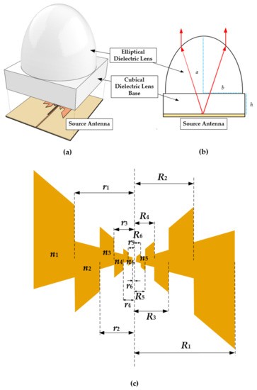
Figure 1.
Proposed trapezoidal log-periodic antenna (LPA): (a) 3-D perspective view (exploded), (b) side view, and (c) trapezoidal LPA radiator structure.
2.1. Trapezoidal Log-Periodic Antenna (LPA)
A layout of the proposed trapezoidal LPA is shown in Figure 1c. The proposed antenna consists of six protruding elements, commonly called “teeth”, alternating on both sides of the (right and left) antenna. The right arm shape is a rotated-and-mirrored image of the left arm. The length of the outermost teeth R1 is determined as
where λ0 is calculated at the lowest operating frequency of the designed antenna. The dimensions of the protruding elements and the relation between each tooth are expressed as [22]
where τ is the geometric ratio; σ is the spacing factor; fn and fn+1 are the design frequencies corresponding to the teeth lengths Rn and Rn+1, respectively; and rn is the distance of the tooth (Rn) from the center of the radiator. The teeth (n1, n2,…, n6) introduce different resonant frequencies. The initial design parameters of the proposed trapezoidal LPA are n = 4, R1 = 433 mil, and r1 = 264 mil, and the values of τ and σ are initially chosen as τ = 0.6 and σ = 0.7 based on [22], which are later verified as the optimum values through parametric optimization. At the LPA input, a CPS line with a line impedance of 188.5 Ω is used. Therefore, in order to feed the antenna with a typical 50 Ω microstrip line, a microstrip-to-CPS transition, which can provide broadband impedance matching and smooth field transformation, is required.
To optimize the performance of the proposed trapezoidal LPA, the antenna design parameters were adjusted through a parametric analysis. The reflection coefficients of the trapezoidal LPA with τ = 0.4, 0.5, and 0.6 (as defined in (1)) are compared in Figure 2. The antenna with τ = 0.6 performs best with a greater-than-10 dB return loss from 5.2 to 40 GHz. Additionally, the performance of the trapezoidal LPA with n = 4, 5, and 6 teeth is displayed in Figure 3.
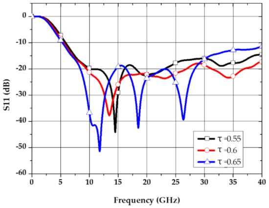
Figure 2.
Simulated S11 of the proposed trapezoidal LPA with varying values of τ.
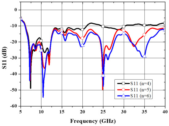
Figure 3.
Simulated S11 of the proposed trapezoidal LPA with different number of teeth (n = 4, 5, and 6).
Since the antenna performance at higher frequencies is determined by the innermost teeth, the antenna with n = 4 or n = 5 shows poor impedance matching at higher frequencies, while the performance at lower frequencies is mostly similar for all the cases of n = 4, 5, and 6. Therefore, n = 6 was selected for the design. The optimized design parameters of the proposed trapezoidal LPA are shown in Table 1.

Table 1.
Design parameters of the proposed trapezoidal LPA with the balun and dielectric lens.
2.2. Microstrip-to-CPS Transition Structure
A configuration and the dimensions of the ultra-wideband microstrip-to-CPS transition are shown in Figure 4 and Table 1, respectively. The transition works as a balun for feeding the trapezoidal log-periodic radiators and was designed using analytical formulas based on conformal mapping [24]. The transition, in the form of an asymmetric CPS structure, connects from a 188.5 Ω CPS line at the LPA input to a 50 Ω microstrip line at the input. The bottom ground linewidth is gradually adjusted to form an optimal impedance taper as illustrated in Figure 4. Moreover, this tapering structure smoothly transforms the field lines between the CPS and microstrip line sections. The trapezoidal LPA with the balun (without a dielectric lens) has an operating bandwidth of 6.05–40 GHz, as shown in Figure 5.
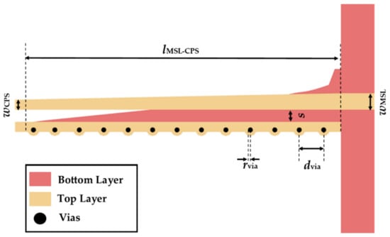
Figure 4.
Proposed microstrip-to-CPS transition.
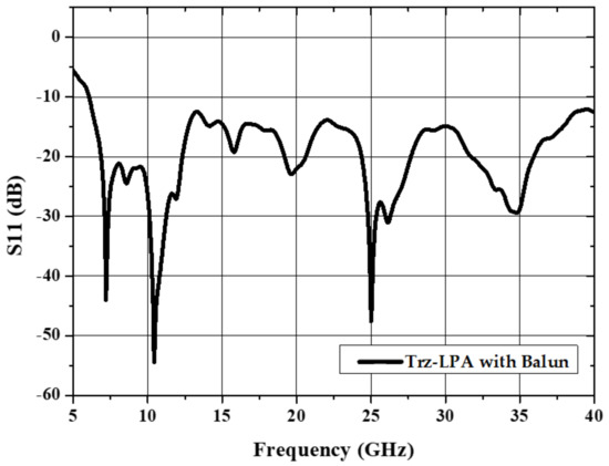
Figure 5.
Simulated S11 of the proposed trapezoidal LPA radiator (without a dielectric lens).
2.3. Elliptical Dielectric Lens
The proposed dielectric lens has an elliptical shape as illustrated in Figure 1b. The design parameters of the proposed elliptical dielectric lens were obtained through the following design process. First, the dielectric lens size was determined using the guidelines in [26]. The height (h) of the dielectric lens was chosen so that the antenna is placed at the focal point of the lens. Then, a parametric study was performed by varying the lengths of the major (a) and minor (b) axes, or controlling the ellipticity (c = a/b) of the lens as shown in Figure 6, where the antenna gains over the operating frequencies are plotted with ellipticity values of 1.33, 1.7, and 2. From this graph, it can be observed that higher ellipticity improves the antenna gain up to a certain level, and then, the overall gain is decreased. Through the parametric study, a maximum antenna gain of 17.8 dB was attained with an ellipticity of c = 1.7. The size of the proposed elliptical lens was selected to be relatively small (i.e., a rectangular base size of 50.8 × 50.8 mm) to reduce the antenna installation spacing. The optimized design parameters of the elliptical lens are listed in the lower part of Table 1.
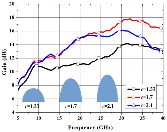
Figure 6.
Simulated gain of the proposed antenna with various values of ellipticity.
Figure 7 shows the simulated reflection coefficients of the proposed trapezoidal LPA with and without the elliptical dielectric lens. The operating bandwidth of the trapezoidal LPA is slightly shifted to higher frequencies due to the increased effective dielectric constant induced by the dielectric lens attached on the antenna board.
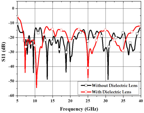
Figure 7.
Simulated S11 of the proposed trapezoidal LPA with/without a dielectric lens.
3. Fabrication and Measurements
A back-to-back microstrip-to-CPS transition structure was fabricated to verify the performance of the antenna feed as shown in Figure 8a. The performance of the microstrip-to-CPS transition structure was measured with a microwave network analyzer (Anritsu MS4644B), and the measured insertion loss (S21) and return loss (S11) are shown in Figure 8b. The transition shows a return loss greater than 10 dB from 6 GHz to over 40 GHz, and had an average insertion loss of 2.4 dB (~1.2 dB per transition) and maximum insertion loss of 3.5 dB (~1.75 dB per transition). The discrepancy between the measured and simulated results could have been caused by the increased loss tangent of the used substrate at higher frequencies and some measurement errors.
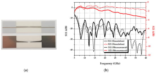
Figure 8.
Microstrip-to-CPS transition in a back-to-back configuration: (a) fabricated prototype; (b) simulated and measured S11 and S21.
The trapezoidal LPA was fabricated using an etching method on a 0.3048 mm-thick Rogers RO4003 substrate (ɛr = 3.38, tan δ = 0.00207). A micro-machining process was used to fabricate the dielectric lens using an HDPE material with a dielectric constant (ɛr) of 2.29 and loss tangent (tan δ) of 0.00031 (at 3 GHz). The dielectric lens was mounted on the top of the LPA radiator using four M4 acrylic screws as shown in Figure 9a. A measurement setup of the proposed LPA integrated with the dielectric lens for antenna radiation patterns and gains is shown in Figure 9b. The simulated and measured S11 values of the proposed lens-integrated LPA are compared in Figure 10. The proposed antenna provides an ultra-wideband impedance bandwidth from 5.2 to 40 GHz. While the measured results agree well with the simulation results at lower frequencies, some discrepancies are noticed at higher frequencies. This disagreement may have been caused by the fabrication tolerances of the antenna and lens, and the cables and connectors used in the measurement setup.
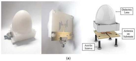
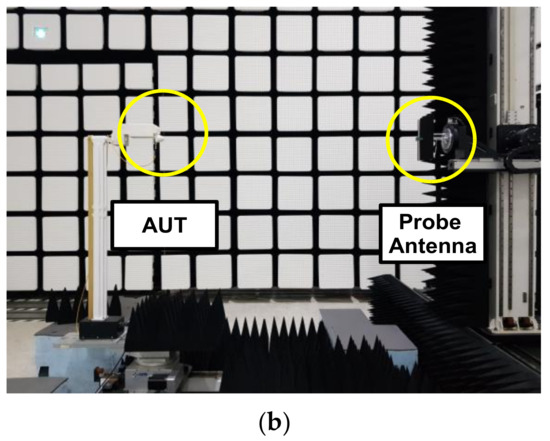
Figure 9.
Proposed dielectric lens antenna: (a) fabricated prototype and assembly illustration; (b) measurement setup for antenna radiation patterns and gains.
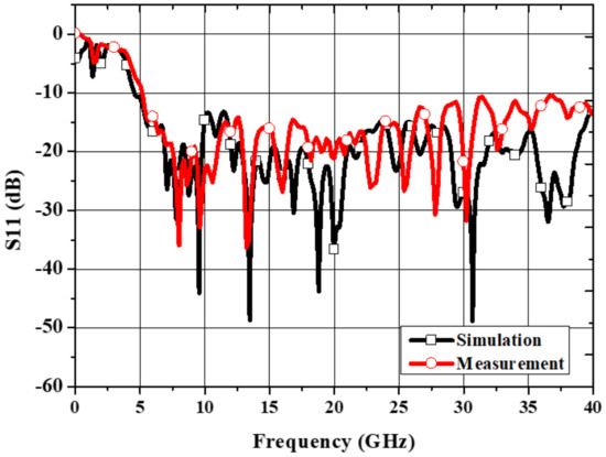
Figure 10.
Simulated and measured S11 results for the proposed antenna.
Figure 11 shows the simulated and measured radiation patterns in the azimuth (φ = 0°) and elevation (φ = 90°) planes at 6, 12, 20, 30, and 40 GHz. As compared with the radiation patterns in the azimuth plane, the radiation patterns in the elevation plane are less symmetrical. Additionally, as observed at both 30 and 40 GHz, the radiation patterns tend to have more prominent side lobes on the left-hand side, around the −60° direction. These are due to the presence of the parallel feeding line of the trapezoidal LPA. The parallel feed line affects the radiation patterns on the elevation plane where the feeding line lies. In addition, it is observed that, as the frequency becomes higher, the main lobe becomes narrower and the number of side lobes increases. Additionally, the measured and simulated gain plots of the proposed lens antenna are shown in Figure 12. The antenna showed a maximum gain of 17.8 dB at 36 GHz.
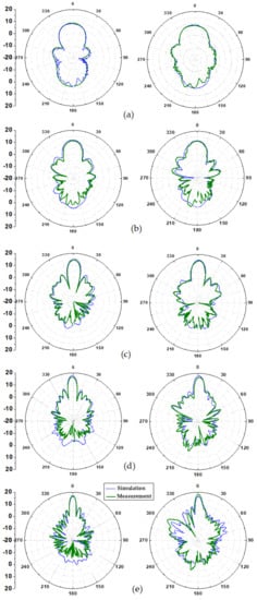
Figure 11.
Simulated and measured radiation patterns in the φ = 0° plane (left column) and φ = 90° plane (right column): (a) 6 GHz, (b) 12 GHz, (c) 20 GHz, (d) 30 GHz, and (e) 40 GHz.
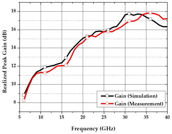
Figure 12.
Simulated and measured gains of the proposed lens-integrated LPA antenna.
The performance of the proposed trapezoidal LPA is compared with the previously reported wideband antennas in Table 2. It can be observed that, for most of the reported wideband LPAs, the antenna gains were under 8 dB. Moreover, the typical feeding technique used for trapezoidal LPAs and toothed LPAs required non-planar perpendicular feeding. As compared with the reported trapezoidal LPAs, the proposed antenna radiator is fully planar, and with the help of the integrated lens, a high gain (i.e., maximum of 17.8 dB) can be obtained with an approximately 50 mm increase in height.

Table 2.
Comparison of the reported log-periodic/ultra-wideband antennas with the proposed lens-integrated LPA antenna.
4. Conclusions
A design for an ultra-wideband trapezoidal LPA integrated with an elliptical dielectric lens is presented. This antenna design utilizes the wideband characteristic of a trapezoidal log-periodic radiator combined with a dielectric lens for radiation pattern improvement. The trapezoidal LPA is fed by an ultra-wideband microstrip-to-CPS transition. The elliptical lens shape is optimized with the LPA radiator for the maximum integrated antenna performance. The proposed antenna was fabricated and measured, showing an ultra-wideband impedance bandwidth of 34.8 GHz (5.2 to 40 GHz) and high gain response. The proposed ultra-wideband lens-integrated antenna is expected to be applied to a variety of emerging broadband communication systems.
Author Contributions
Conceptualization, S.H.N. and G.H.L.; methodology, S.H.N.; software, S.H.N.; validation, S.H.N. and G.H.L.; investigation, S.H.N.; resources, S.H.N.; data curation, S.H.N.; writing—original draft preparation, S.H.N.; writing—review and editing, S.H.N., G.H.L., S.K., H.C.C., and K.W.K.; visualization, S.H.N.; supervision, H.C.C. and K.W.K.; project administration, K.W.K.; funding acquisition, K.W.K. All authors have read and agreed to the published version of the manuscript.
Funding
This research was funded by the Ministry of Education, Science and Technology and the Ministry of Education, South Korea.
Acknowledgments
This work was supported by the National Research and Development Program through the National Research Foundation of Korea (NRF), funded by the Ministry of Education, Science and Technology, under Grant NRF-2018R1D1A3B07047848 and in part by the 4 BK21 Project funded by the Ministry of Education, South Korea.
Conflicts of Interest
The authors declare no conflict of interest.
References
- Balani, W.; Sarvagya, M.; Ali, T.; Manohara Pai, M.M.; Anguera, J.; Andujar, A.; Das, S. Design Techniques of Super-Wideband Antenna-Existing and Future Prospective. IEEE Access 2019, 7, 141241–141257. [Google Scholar] [CrossRef]
- Kumar, S.; Lee, G.H.; Kim, D.H.; Haunan, N.S.; Choi, H.C.; Kim, K.W. Compact planar super-wideband monopole antenna with four notched bands. Electronics 2020, 9, 1204. [Google Scholar] [CrossRef]
- Okas, P.; Sharma, A.; Gangwar, R.K. Circular base loaded modified rectangular monopole radiator for super wideband application. Microw. Opt. Technol. Lett. 2017, 59, 2421–2428. [Google Scholar] [CrossRef]
- Okas, P.; Sharma, A.; Das, G.; Gangwar, R.K. Elliptical slot loaded partially segmented circular monopole antenna for super wideband application. AEU Int. J. Electron. Commun. 2018, 88, 63–69. [Google Scholar] [CrossRef]
- Okas, P.; Sharma, A.; Gangwar, R.K. Super-wideband CPW fed modified square monopole antenna with stabilized radiation characteristics. Microw. Opt. Technol. Lett. 2018, 60, 568–575. [Google Scholar] [CrossRef]
- Oskouei, H.D.; Mirtaheri, A. A monopole super wideband microstrip antenna with band-notch rejection. Prog. Electromagn. Res. Symp. 2017, 2019–2024. [Google Scholar] [CrossRef]
- Figueroa-Torres, C.A.; Luis, M.-M.J.; Lobato-Morales, H.; Chavez-Perez, R.A.; Calvillo-Tellez, A. A novel fractal antenna based on the sierpinski structure for super wide-band applications. Microw. Opt. Technol. Lett. 2013, 55, 2562–2568. [Google Scholar] [CrossRef]
- Ur Rahman, M.; Naghshvarianjahromi, M.; Mirjavadi, S.S.; Hamouda, A.M. Bandwidth enhancement and frequency scanning array antenna using novel UWB filter integration technique for OFDM UWB radar applications in wireless vital signs monitoring. Sensors 2018, 18, 3155. [Google Scholar] [CrossRef]
- Rahman, M.; Haider, A.; Naghshvarianjahromi, M. A Systematic Methodology for the Time-Domain Ringing Reduction in UWB Band-Notched Antennas. IEEE Antennas Wirel. Propag. Lett. 2020, 19, 482–486. [Google Scholar] [CrossRef]
- Rahman, M.U.; Ko, D.S.; Park, J.D. A compact multiple notched ultra-wide band antenna with an analysis of the CSRR-TO-CSRR coupling for portable UWB applications. Sensors 2017, 17, 2174. [Google Scholar] [CrossRef]
- Zhang, Y.; Member, S.; Jiao, Y.; Member, S.; Liu, S. 3-D-Printed Comb Mushroom-Like Dielectric Lens for Stable Gain Enhancement of Printed Log-Periodic Dipole Array. IEEE Antennas Wirel. Propag. Lett. 2018, 17, 2099–2103. [Google Scholar] [CrossRef]
- Zhou, W.; Liu, J.; Long, Y. A broadband and high-gain planar complementary yagi array antenna with circular polarization. IEEE Trans. Antennas Propag. 2017, 65, 1446–1451. [Google Scholar] [CrossRef]
- Pirai, M.; Hassani, H.R. Size reduction of microstrip LPDA antenna with top loading. IEICE Electron. Express 2009, 6, 1528–1534. [Google Scholar] [CrossRef][Green Version]
- Yeo, J.; Lee, J.I. Miniaturized LPDA antenna for portable direction finding applications. ETRI J. 2012, 34, 118–121. [Google Scholar] [CrossRef]
- Elsheakh, D.; Abdallah, E. Compact printed log-periodic dipole antenna for terrestrial digital video broadcast application. Microw. Opt. Technol. Lett. 2014, 56, 1002–1007. [Google Scholar] [CrossRef]
- DuHamel, R.; Ore, F. Logarithmically periodic antenna designs. In Proceedings of the IRE International Convention Record, New York, NY, USA, 21–25 March 1966; pp. 139–151. [Google Scholar] [CrossRef]
- Rumsey, V.H. Frequency Independent Antennas; Academic Press: New York, NY, USA, 1966. [Google Scholar]
- Duhamell-, R.H.; Isbell, D.E. Broadband Logarithmically Periodic Antenna Structures. In Proceedings of the IRE International Convention Records, New York, NY, USA, 21–25 March 1966; pp. 119–128. [Google Scholar]
- Telfer, L.F.; Ramani, T.R.G.; Beaula, P.G.; Priya, M.S.D. Design and Optimization of Log Periodic Toothed Antenna for UWB Applications. Int. J. Eng. Innov. Res. 2013, 2, 2277–5668. [Google Scholar]
- Simon, J.; Flores-Gonzalez, J.R.; Gonzalez-Salas, J.S.; Flores-Troncoso, J. A log-periodic toothed trapezoidal antenna for rf energy harvesting. Microw. Opt. Technol. Lett. 2015, 57, 2765–2768. [Google Scholar] [CrossRef]
- Patre, S.R.; Singh, S.; Singh, S.P. Study of Trapezoidal Toothed Log-periodic Antenna Fed Through Tapered Microstrip Line-to-Coplanar Stripline Transition. Microw. Opt. Technol. Lett. 2015, 57, 1671–1677. [Google Scholar] [CrossRef]
- Patre, S.R.; Singh, S.P. Dielectric-loaded trapezoidal toothed log-periodic antenna. Int. J. RF Microw. Comput. Eng. 2017, 27, 1–8. [Google Scholar] [CrossRef]
- Edalati, A.; Shao, W.; McCollough, T.; McCollough, W. A novel cavity backed monopole antenna with UWB unidirectional radiation. Prog. Electromagn. Res. C 2017, 72, 1–13. [Google Scholar] [CrossRef]
- Lee, G.H.; Mohyuddin, W.; Choi, H.C.; Kim, K.W. Asymmetric Ultra-Wideband Microstrip-to-Coplanar Stripline Transition. IEEE Microw. Wirel. Components Lett. 2018, 28, 386–388. [Google Scholar] [CrossRef]
- Seeger, K. Microwave Measurement of the Dielectric Constant of High-Density Polyethylene. IEEE Trans. Microw. Theory Tech. 1991, 39, 352–354. [Google Scholar] [CrossRef]
- Filipovic, D.F.; Gearhart, S.S.; Rebeiz, G.M. Double-Slot Antennas on Extended Hemispherical and Elliptical Silicon Dielectric Lenses. IEEE Trans. Microw. Theory Tech. 1993, 41, 1738–1749. [Google Scholar] [CrossRef]
- Chen, S.Y.; Wang, P.H.; Hsu, P. Uniplanar log-periodic slot antenna fed by a CPW for UWB applications. IEEE Antennas Wirel. Propag. Lett. 2006, 5, 256–259. [Google Scholar] [CrossRef]
- Tang, M.C.; Shi, T.; Ziolkowski, R.W. Planar ultrawideband antennas with improved realized gain performance. IEEE Trans. Antennas Propag. 2016, 64, 61–69. [Google Scholar] [CrossRef]
Publisher’s Note: MDPI stays neutral with regard to jurisdictional claims in published maps and institutional affiliations. |
© 2020 by the authors. Licensee MDPI, Basel, Switzerland. This article is an open access article distributed under the terms and conditions of the Creative Commons Attribution (CC BY) license (http://creativecommons.org/licenses/by/4.0/).