1. Introduction
The mechanism of harvesting photons in the cells of photosynthetic organisms enables them to function effectively, even at low light intensities [
1,
2]. In addition, the quantum efficiency in generating separated electron–hole pairs due to absorbed photons inside the photosynthetic proteins is almost 100% [
2]. Due to these unique characteristics, the application of photosynthetic proteins and cells has attracted growing interest for the fabrication of solar cells [
3,
4]. While the low overall efficiency and the limited lifetime of biomaterials are serious challenges for efficient energy production, the elegant mechanism of light absorption and charge separation in photosynthetic proteins is inspiring for the fabrication of ultrasensitive photodetectors. In this study, we have used the reaction center (RC) and the core complex of the RCs, surrounded by a light-harvesting unit (RC-LH1) from a photosynthetic bacterium,
Rhodobacter (Rb.) sphaeroides, to make photo-sensors. It should be noted that the application of photosynthetic proteins in sensing devices is new and challenging. The results presented in this work are a proof of concept for the feasibility of employing RCs and RC-LH1s as the photoactive elements in photodetectors. Yet, due to some limitations, such as the limited absorption spectrum in the proteins (~750 nm < λ < ~950 nm), the performance of a bio-photodetector is not comparable to state-of-art technologies using no biomaterials.
Within a photosynthetic bacterium, for every RC, there are light-harvesting (LH) proteins that contain pigments which absorb photons like antennae. Through a Förster resonance mechanism, the energy of the photons is funneled to the closest light-harvesting protein layer (LH1) encircling the RC, through which the energy is delivered to the RC with high efficiency. As shown in
Figure 1a, the RC protein is surrounded by the LH1 layer, forming the RC-LH1 core complex. The charge separation process occurs inside the RC proteins.
Figure 1b is a schematic of the RC showing the structure of the protein, consisting of three protein subunits called L, M and H, with embedded cofactors that are the main elements in converting photons to electric charges. A photon absorbed by an RC generates an excited state in a pair of bacteriochlorophylls (BChls), called the special pair (P). The excited electron is then transferred to an accessory BChl (B
A), then to a bacteriopheophytin (BPhe) and subsequently to a primary (Q
A) and secondary (Q
B) quinone [
5]. As shown in
Figure 1c, the electron path is in favor of the electron moving from P to Q
B due to the lower energy level at Q
B. This process leaves a hole (positive charge) at P, with an electron at Q
B forming a dipole inside the RC. The multi-step electron transfer facilitates the charge separation and lowers the probability of charge recombination inside the RC. Due to this process, the photo-generated dipole is very stable, with a recombination time of ~1 s [
6].
In the native organism, the negative charge at Q
B is neutralized by a proton acquired from the cell cytoplasm forming hydroquinone. The positive charge is also transferred from P
+ to a cytochrome
c (cyt
c) protein, which acts as a charge mediator [
6]. The interaction between cyt
c and the RC occurs through a docking mechanism, in which cyt
c binds to the RC residues in a depression on the P side of the protein (
Figure 1b) [
7]. As we have shown previously (and also applied in this study), the interaction between an RC and a cyt
c is sufficiently stable for immobilization of properly oriented RCs [
8,
9,
10].
To employ the unique mechanism of photon absorption and charge separation in RCs for light detection, it is required to keep them in an electrochemical cell. In a conventional approach, the proteins are immobilized on the surface of a conductive electrode to be used in the electrochemical cell [
5,
9,
11,
12,
13]. The photo-generated electrons or holes are transferred to the conductive electrode to produce a photocurrent that is proportional to the intensity of the absorbed light. In this design, the orientation of the immobilized RCs is critical for collecting either the negative or positive charges. Various immobilization methods using linker molecules and specific tags on the protein have been demonstrated before [
4]. Nevertheless, those approaches rely on the charge transfer from the protein to the electrode, which can be limited due to the relatively large distance between either the P
+ or Q
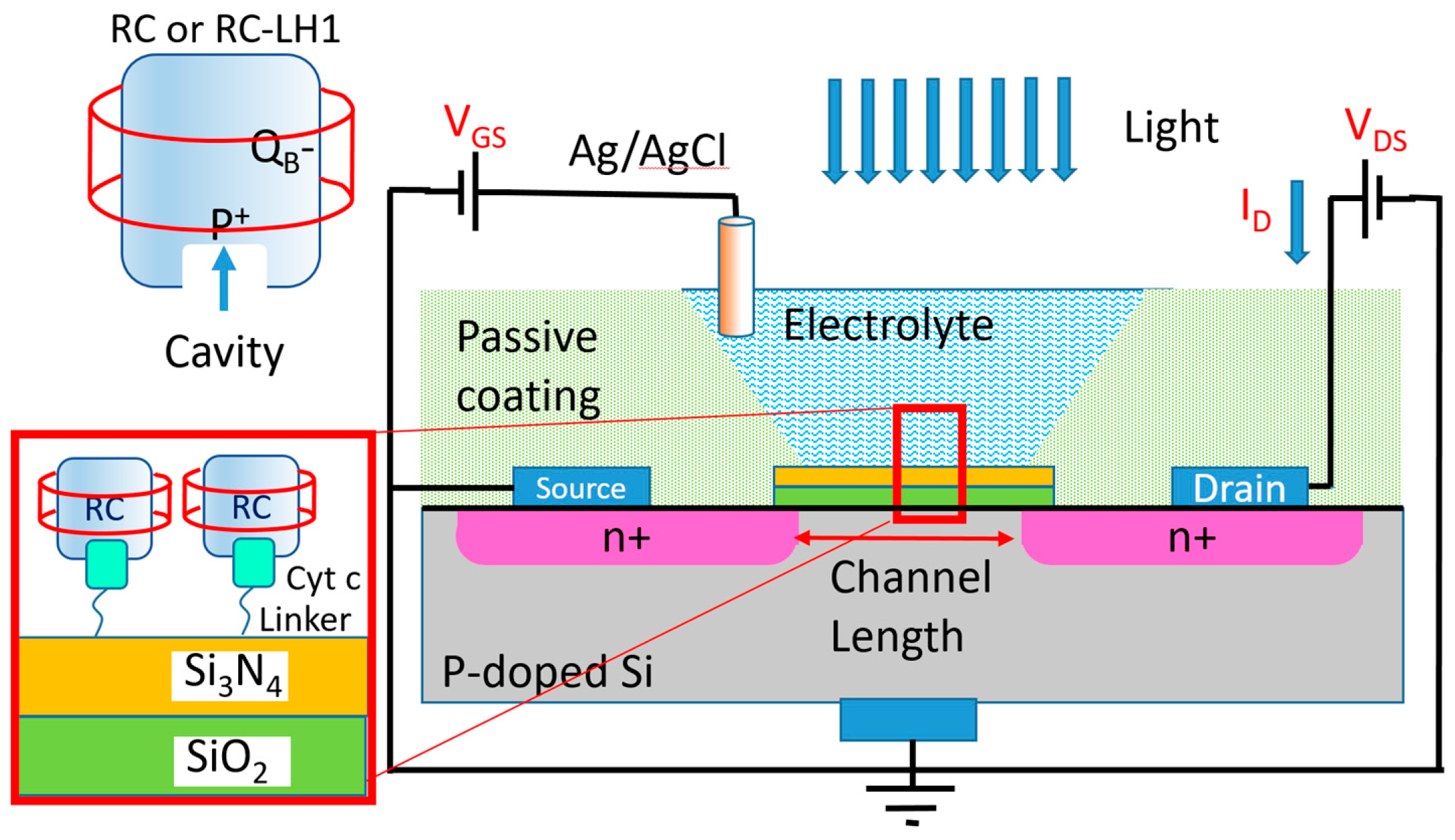
B− on the RC and the electrode surface. The novel approach in this work is to employ the proteins in an electrochemical transistor design, where the generated dipole can change the transistor’s drain current without any need for the charge transfer from the protein. With this design, RCs can act as photosensitive elements in liquid media that are potentially suitable for designing miniaturized spectrometers operating in water and other liquids, such as blood.
To eliminate charge transfer limitation, a common approach in biosensors is to use an electrochemical transistor with the immobilized biomaterials on top of their insulating layer [
14]. The mechanism of operation in an electrochemical transistor is very similar to a metal–oxide field effect transistor (MOSFET) that is well explained in [
15]. The insulating layer (the SiO
2 + Si
3N
4 layer in
Figure 2) between the electrolyte and the semiconductor forms a capacitor. The biomaterials attached to the insulating layer at the electrolyte side impact the charge distribution on the semiconductor layer between the drain and source contacts. Hence, the effect of the biomaterials can be measured via monitoring the drain current without any need for the charge transfer from the biomaterial to any of the electrochemical electrodes. Different forms of bio-transistors (also known as Bio-FETs) have been reported for the detection of proteins, DNAs, viruses and cells [
16]. In almost all of these devices, the transistor detects successful coupling between the target biomaterial in the electrolyte and the engineered immobilized bio-receptor [
14]. However, in this work, we have employed the photo-generated dipoles on already immobilized proteins on top of the gate insulator. Two Bio-FETs (one with the immobilized RCs and the other one with a layer of RC-LH1 as a photoactive layer) were studied as photodetectors by monitoring their response to light at various wavelengths.
Figure 2 shows the schematic of the fabricated devices.
2. Materials and Methods
Silicon-based electrochemical transistors with 98 nm thick SiO
2 and 100 nm thick Si
3N
4 gate insulators were purchased from Microsense. The gate area of the transistor was approximately W = 2 mm × L = 1 mm. The transistors were immersed into disposable cuvettes (1 cm × 1 cm × 4 cm) filled with a solution of 0.75 mM of methyl viologen (MV) in a 0.1 M Tris-HCl buffer (pH 8.0) as the electrolyte. An Ag/AgCl reference electrode was used as the gate contact (
Figure 2). The transistors were tested before and after protein immobilization under dark and light conditions.
Wild-type RCs from
Rb. sphaeroides were isolated using a modified version of the method of Goldsmith and Boxer [
5,
17,
18]. Briefly, cells were centrifuged at 9000
g and suspended in 10 mM Tris (pH 8), 150 mM NaCl and 2 mM MgCl
2 [
5]. The cells were broken by two passages through a French press. Broken cells were centrifuged at 9000
g to pellet unbroken cells, and the supernatant was centrifuged overnight at 30,000 rpm in a Beckman Coulter Type 70 Ti rotor to pellet the membranes. Membranes were suspended in 10 mM Tris (pH 8) and 150 mM NaCl and solubilized with 1.5%
N,
N dimethyldodecylamine N-oxide (LDAO). Solubilized membranes were ultra-centrifuged at 541,000
g, and 6-His-tagged RCs were purified from the supernatant using affinity chromatography [
19]. The concentration of RCs after purification was determined by their absorption at 804 nm, as described by Goldsmith and Boxer [
18].
The production and purification of the RC-LH1 in
Rb. sphaeroides were similar to the description by Abresch et al. [
20]. All protein solutions utilized a buffer of 10 mM Tris-HCl, pH 8, and 25 mM NaCl. Membranes were solubilized with 0.5% sodium cholate combined with 4%
n-octyl-
β-D-glucopyranoside (BOG), and the 6-His-tagged proteins were bound to a Ni
2+/NTA column. The detergent was then changed to a combination of 0.2% sodium cholate and 0.06%
n-dodecyl-
β-D-maltopyranoside (DDM) in all of the following steps. The column was washed with 10 column volumes of buffer solution containing 5 mM imidazole, and the protein was eluted from the column by raising the concentration of the imidazole to 150 mM. The column eluate was layered onto a sucrose gradient (15% to 35%) and centrifuged in a Beckman SW41 swinging bucket rotor at 4 °C for 44 h at 30,000 rpm. The bottom of the two bands was collected, and the sucrose was removed by dialysis.
Buffer solutions with RC and RC-LH1 concentrations of 5 µM were prepared and used for the fabrication of the Bio-FETs. A hybrid linker structure consisting of a self-assembled monolayer (SAM) of 10-carboxydecylphosphonic acid and immobilized cyt c was used to immobilize the photosynthetic proteins on the Si3N4 layer of the transistor from the P+ side of the proteins. The immobilization was done by first forming the SAM by inserting the transistor into an ethanolic solution of 10 mM 10-carboxydecylphosphonic acid (Dojindo) for 4 h at room temperature. After this step, the transistor was rinsed in ethanol, followed by a deionized water rinse to remove the loosely bound SAM. Equine cyt c (purchased from Sigma and used without purification) was deposited on the SAM by inserting the Bio-FET into a 0.8 mM solution of cyt c in a # mM Tris buffer (pH 8.0) for 24 h at room temperature. RC and RC-LH1 incubation were carried out by drop-casting 20 μL of the protein solutions (5 µM) on top of the active area of the transistor and keeping it at 4 °C for 24 h. The devices were rinsed before being used in the electrochemical cell.
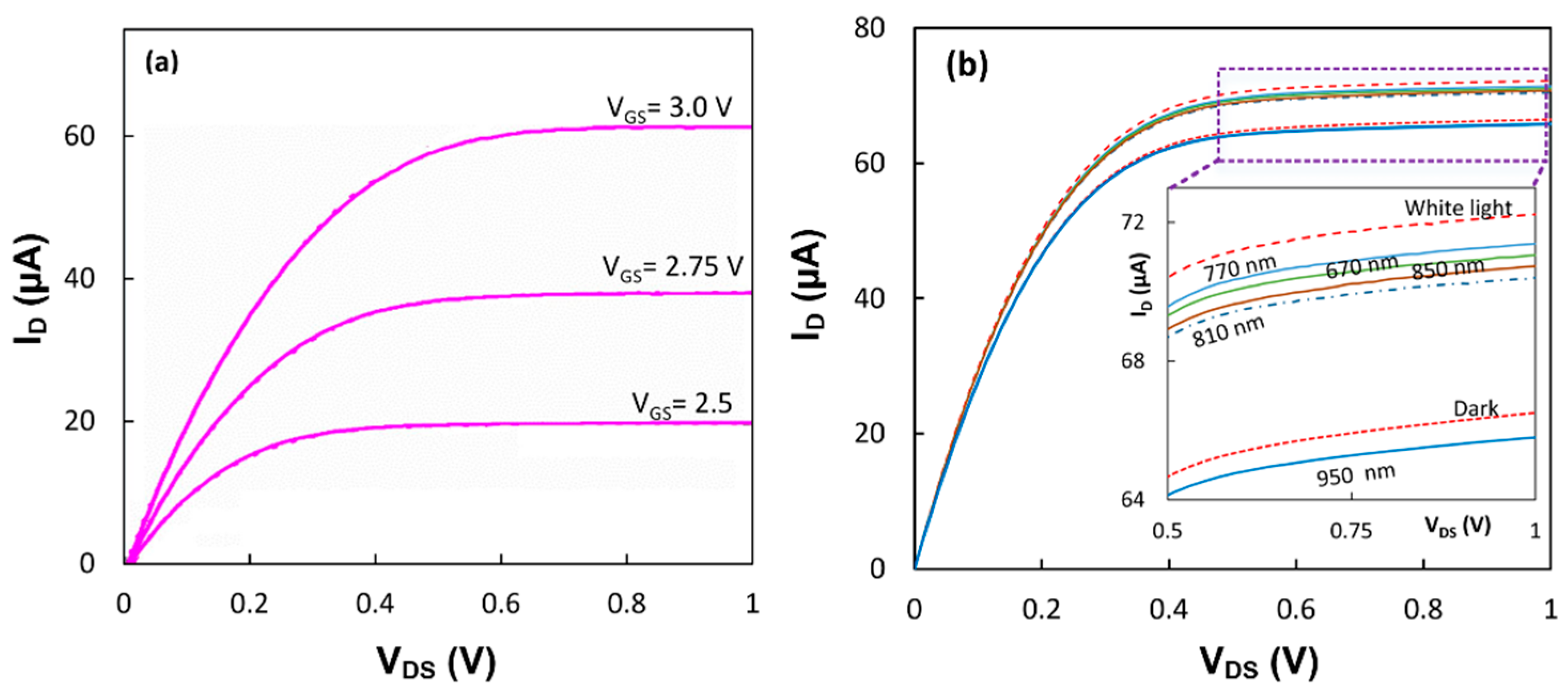
The electrochemical cells were tested using a custom-made setup, including a dark box with a white light-emitting diode (LED) and a multi-wavelength LED (MTMD6788594SMT6 from Marktech Optoelectronics) as the light sources inside the box. Each LED was biased with a 20 mA current to get white light emission and single wavelength emissions at 670, 770, 810, 850 and 950 nm. From the datasheet of the LED, the intensity of the monochromatic light was estimated to be ~3 μW/cm2 at the transistor surface. The transistor was characterized using a 2602A Keithley instrument. The Keithley instrument and the pulse current source for the LEDs were controlled through LabTracer 2.0 software.
3. Results
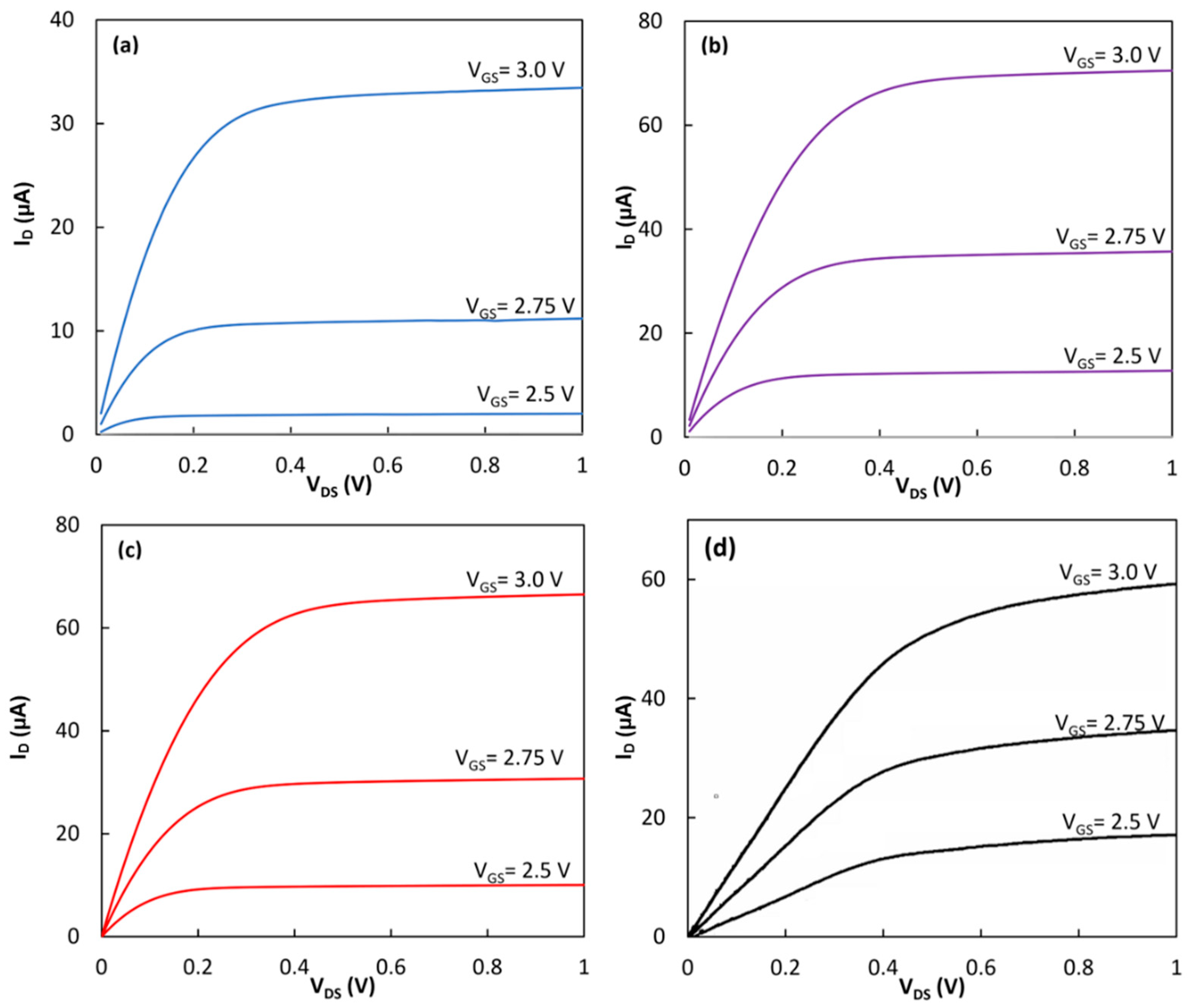
First, an electrochemical transistor without any coating on the gate insulator was tested under dark conditions. According to the datasheet of the device, the transistors had a threshold voltage of
Vth = ~2.4 V. To obtain the output characteristics of the devices, a constant voltage was applied between the gate (i.e., the Ag/AgCl electrode) and the source while the voltage of the drain was scanned from 0.0 V to 1.0 V, and the drain current was measured.
Figure 3a shows the response of the transistor at three different bias voltages of
VGS = 2.5 V, 2.75 V and 3.0 V. The device clearly showed the enhancement mode operation with the distinct triode and saturation regimes. The saturation current reached 33.4 µA at
VDS = 1.0 V when V
GS was 3.0 V. The same device was tested after the formation of the SAM and immobilization of the cyt
c on the gate insulating layer.
Figure 3b shows the output characteristics of the device after forming the hybrid linker on top of the gate insulator. In this case, the drain current was increased to 70.5 µA. RC proteins without the LH1 were immobilized on the hybrid linker using the natural docking mechanism between the RC and the cyt
c. The device with the immobilized RC was then tested in the dark (
Figure 3c). In this case, the drain current dropped to 66.5 µA at
VDS = 1.0 V and
VGS = 3.0 V. The same functionalization process to deposit the hybrid linker on the Si
3N
4 layer was performed on a different transistor. Then, the RC-LH1 was immobilized on the second transistor.
Figure 3d shows the output characteristics of the device under dark conditions. A drain current of 59.0 µA was achieved from the transistor.
Both devices with the immobilized proteins were tested under white and monochromic light from LEDs.
Figure 4a shows that the output characteristics of the device with the RC-LH1 proteins had an increase in the drain current from its dark value of 59.0 µA to 62.0 µA under white light when the gate was biased at 3.0 V and the
VDS was 1.0 V. The output characteristics of the first device in the dark and upon illumination with white and monochromic light are shown in
Figure 4b. While the current increased from 66.5 µA in the dark to 72.2 µA upon white light illumination, the value of the current was different under monochromic lights.
The drain current difference, Δ
ID, between light and dark at
VDS = 1.0 V and
VGS = 3.0 V for each wavelength has been calculated for both transistors. As shown in
Figure 5, Δ
ID has a relatively consistent correlation with the absorption spectrum in the RC and RC-LH1 proteins.
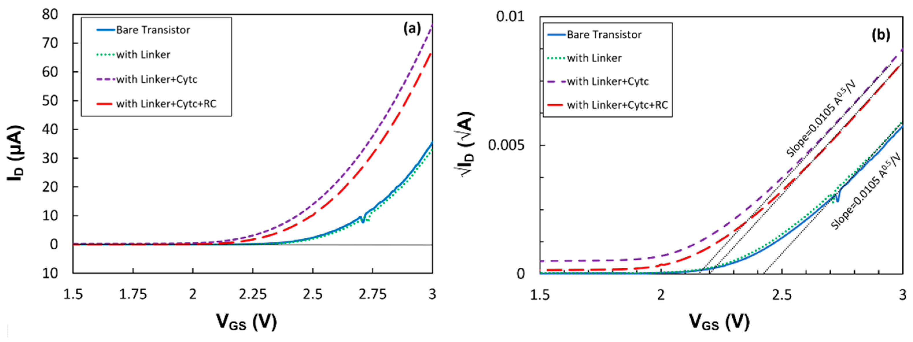
4. Discussion
The drain saturation current,
ID, in an enhancement transistor is expressed by [
15]
where
μ is the mobility of the carrier in the channel of the transistor,
W/
L is the channel’s width-to-length ratio and
CG is the gate capacitance. Since
μ, W and L do not change after the formation of the linker and immobilization of the proteins, the variation in the drain current can either be due to the change in the gate capacitance or the threshold voltage. To understand the effect of different layers, trans-characteristics (
ID -
VGS) of the first transistor at
VDS = 1.0 V before and after the deposition of each layer have been studied and plotted in
Figure 6a. Since there is a quadratic function between the current and voltage, the square root of the drain current versus
VGS is plotted in
Figure 6b. The results clearly show that the SAM layer of the linker molecule had a negligible impact on the threshold voltage and
CG. However, the immobilized cyt
c shifted the threshold voltage from
Vth = 2.42 V to 2.15 V. Since the slope had not changed, the shift in the threshold voltage implies that the positive charge, most likely from the Fe
2+ inside the cyt
c, affected the density of the electrons in the silicon channel [
15]. This can be explained via the flat-band voltage in an FET device, which is a function of fixed charges at the gate insulator interface [
15]. RC immobilization also showed a shift in the threshold voltage without changing the gate capacitance. The increase in the threshold voltage to
Vth = 2.20 V indicates that the center of charge in the coupled cyt
c with the RC shifted away from the gate insulator. However, the larger drain current under illumination than in the dark suggests that the photo-generated dipoles inside RCs reduce the threshold voltage in the transistor p15]. While the results show the compatibility between the drain current and the absorption spectrum of the proteins, it is expected that shorter linkers on the gate insulator would enhance the effect of the dipoles on the drain current and improve the photosensitivity of the devices.


