Article

Low-Speed Performance Improvement of Direct Torque Control for Induction Motor Drives Fed by Three-Level NPC Inverter

by
Samer Saleh Hakami
,
Ibrahim Mohd Alsofyani
and
Kyo-Beum Lee
*
Department of Electrical and Computer Engineering, Ajou University, 206, World cup-ro, Yeongtong-gu, Suwon 16499, Korea
*
Author to whom correspondence should be addressed.
Electronics 2020, 9(1), 77; https://doi.org/10.3390/electronics9010077
Submission received: 10 December 2019 / Revised: 19 December 2019 / Accepted: 24 December 2019 / Published: 1 January 2020
(This article belongs to the Special Issue High Power Electric Traction Systems)

Abstract

:
Classical direct torque control (DTC) is considered one of the simplest and fastest control algorithms in motor drives. However, it produces high torque and flux ripples due to the implementation of the three-level hysteresis torque regulator (HTR). Although, increasing the level of HTR and utilizing multilevel inverters has a great contribution in torque and flux ripples reduction, stator flux magnitude of induction motor (IM) droops at every switching sector transition, particularly at low-speed operation. This problem occurs due to the utilization of a zero voltage vector, where the domination of stator resistance is very high. A simple flux regulation strategy (SFRS) is applied for low-speed operation for DTC of IM. The proposed DTC-SFRS modifies the output status of the five-level HTR depending on the flux error, torque error, and stator flux position. This method regulates the stator flux for both forward and reverse rotational directions of IM with retaining the basic structure of classical DTC. By using the proposed algorithm, the stator flux is regulated, hence pure sinusoidal current waveform is achieved, which results in lower total harmonics distortion (THD). The effectiveness of the proposed DTC-SFRS is verified through simulation and experimental results.

1. Introduction

Approximately 60% of the total industrial applications utilize induction motor (IM) drives for its simple mechanical construction, reliability, ruggedness, low-cost, and low maintenance requirements. However, the nonlinear system of IM is complex due to instantaneous changes during its operation [1]. Therefore, the development of a variable speed drive with a robust control technique is compulsory for improving the performance and efficiency of the IM drives [2]. Among these control techniques are direct torque control (DTC), which is well known for its simplicity and quick dynamic response compared to field orientated control (FOC) [3]. Despite its fast dynamic control and less sophisticated control structure, there are some associated drawbacks of classical DTC; high torque and flux ripples, variable switching frequency, and stator flux-droop at low-speed regions of induction motor (IM) drives [4,5].
As reported in the literature, there has been some effort to improve the operation of classical DTC. The first approach was introducing space vector modulation (SVM) to DTC [6,7,8]. This technique uses the reference voltage vector; however, the appropriate reference voltage cannot be easily estimated. In addition, for the proper regulation of torque and flux, additional control techniques are required [9,10,11,12,13]. Model predictive control (MPC) is considered as the second alternative control strategy that requires a predefined cost function to predict output states to obtain state variables and execute control object optimization [14,15,16,17,18,19,20,21]. Another approach to improving DTC is by controlling the duty-ratio of applied voltage vectors (DDTC) [22,23]. In DDTC, the duty-ratio of applied voltage vectors are adjusted to reduce the ripples of torque and flux. The critical issue in implanting the DDTC is how to determine the duty-ratio. Thus far, there are a variety of methods to obtain the duty-ratio and they differ in the optimization aims and vector numbers. The specific methods include an analytical calculation based on torque ripple minimization [24] or equalizing the torque with the reference value over one cycle [25]. Although the torque ripple is reduced, these methods are usually complex depending on the knowledge of machine parameters. In addition, the switching frequency is not fixed, and it has poor performance for the low-speed operation of IM.
In addition to the merits of these sophisticated algorithms used to improve the performance of classical DTC, torque and flux ripples can be minimized if multilevel inverters (MLIs) are employed because the output voltage of MLIs is synthesized with more discrete levels compared to a two-level inverter. Among MLIs topologies used in DTC drives, the three-level neutral-point clamped (NPC) inverter is the most prominent. In DTC fed by a three-level NPC inverter, the selection of applied voltage vectors is expanded, thus different speeds of stator flux linkage can be achieved to have a predominant control of torque and flux [26,27,28,29].
Recently, to meet the requirements of most advanced industrial applications such as cranes, tractions, and winches, researchers have focused on improving the low-speed operation of IM in both forward and reverse directions, where the stator flux is unregulated due to the domination of stator resistance and extensive utilization of zero voltage vector. In references [30,31], the authors have replaced the classical HTR by an overlapping-carriers regulator. Lower torque and flux ripples and constant switching frequency were achieved. Moreover, the stator flux of IM is regulated at the low-speed region. However, the dynamic response is slow because of the proportional-integral (PI) controller as compared to the classical DTC and it has some limitations when implementing on the DSP control board.
This paper proposes a simple flux regulation strategy (SFRS) based DTC to improve the low-speed operation of IM fed by a three-level NPC inverter. This method modifies the output status of the conventional five-level HTR depending on flux error, torque error, and stator flux position. Based on the torque error, the proposed DTC-SFRS detects the rotational direction of the IM. Moreover, the position of the stator flux vector is checked by using a simple arrangement of space vector diagram of the three-level NPC inverter. By using the proposed DTC-SFRS, the stator flux of IM is regulated while retaining the basic structure of classical DTC. Furthermore, the pure sinusoidal current waveform is achieved, which results in lower total harmonics distortion (THD). Simulation and experimental results validate the effectiveness of the proposed DTC-SFRS.

2. Mathematical Model of IM

IM can be mathematically modelled as expressed [20]:
v s = R s i s + d λ s d t
0 = R r i r j ω r λ r + d λ r d t
λ s = L s i s + L m i r
λ r = L r i r + L m i s
T e = 3 2 p . Im ( λ s i s )
where vs denotes the stator voltage vector, ψs and ψr represent the stator, and rotor flux vectors, respectively. is and ir are the stator and rotor currents vectors. ωr is the rotor angular motor velocity in rad/s. Ls, Lr, Lm, Rs, and Rr represent the stator inductor, rotor inductor, mutual inductor, stator resistor, and rotor resistor, respectively. p represents the number of pole pairs, while Te denotes the electromagnetic torque.

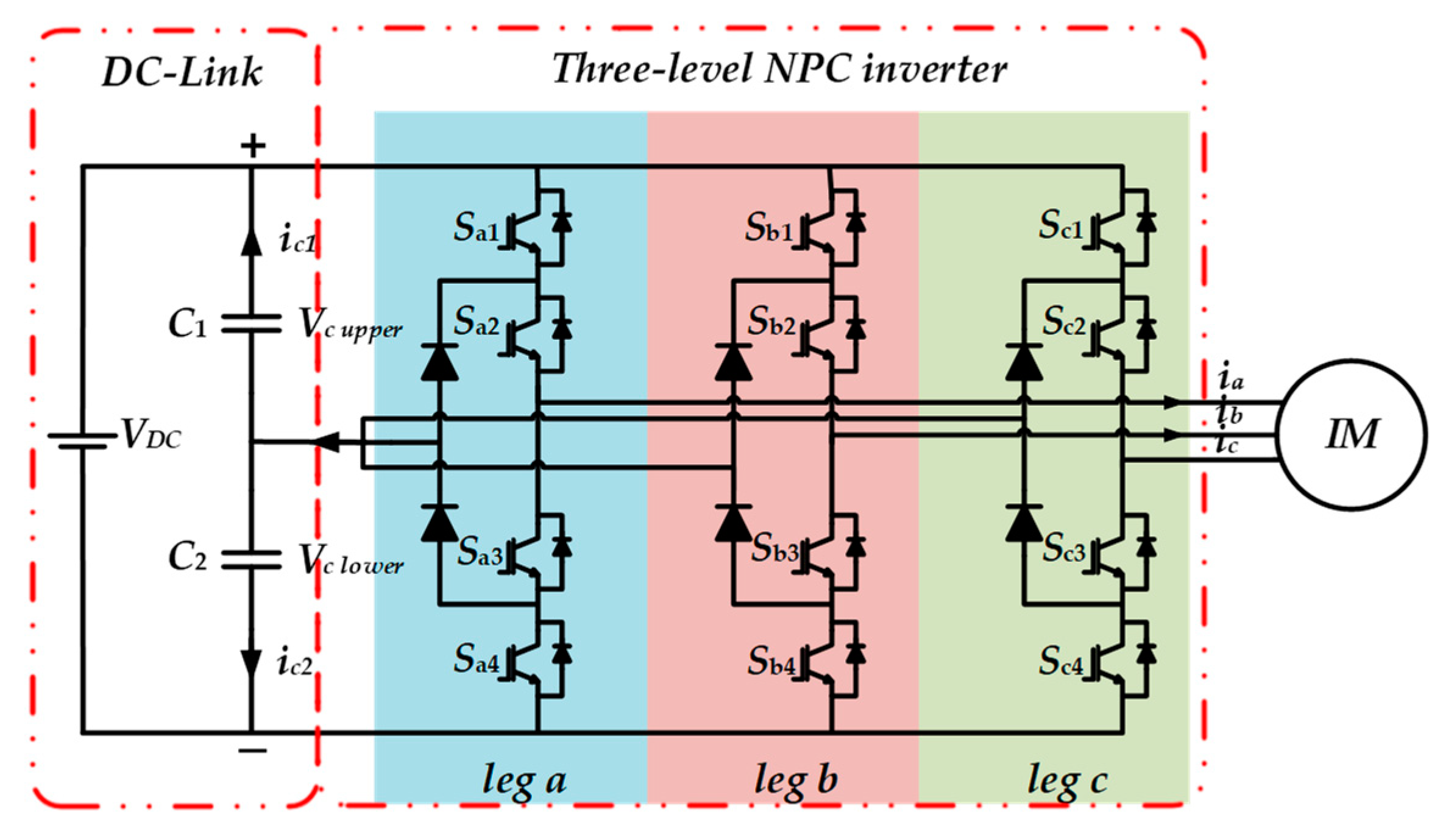
3. Three-Level Neutral-Point-Clamped Inverter for DTC of IM

Among multilevel inverters, a three-level neutral-point clamped (NPC) inverter is the most commonly used topology in DTC drives. It contributes to torque and flux ripples reduction. Moreover, the degree of freedom for selecting the voltage vectors is higher; therefore, the stator flux of IM can be controlled for various speed operation. The basic structure of a three-level NPC inverter is illustrated in Figure 1. It can be seen from the circuit topology that a three-level NPC consists of three legs and four switches in each leg. The space vector diagram and switching states of three-level NPC inverter are shown in Figure 2.
There are 19 distinct voltage vectors: Large (V1−V6), medium (V7−V12), small (V13−V18), and zero (V0). These voltage vectors generate 27 switching states, which represent the connection of stator to the DC power supply “−1,” “0,” and “1,” which denotes a connection to the negative DC rail, neutral point, and positive DC rail, respectively. Simplicity, the space vector diagram will be divided into 6 sectors and each sector will have two subsectors “a” and “b”. This arrangement will reduce the complexity of the three-level NPC inverter for DTC of IM drives.

4. Classical DTC of IM and Its Limitations at Low-Speed Regions

Figure 3 shows the complete structure of classical DTC for controlling the IM fed by a three-level NPC inverter. The main idea of this topology is applying hysteresis torque and flux regulators for controlling both stator flux ψs and electromagnetic torque Te. The designs of these hysteresis regulators are shown in Figure 4. With the output of the hysteresis regulators, the inverter switching states can be selected from a predefined switching table (see Table 1).
The output rules for the five-level HTR are expressed as:
T e   s t a t u s = { + 2 f o r T e   e r r o r Δ T e   + 1 f o r Δ T e   / 2   < T e   e r r o r < Δ T e   + 0 f o r 0 < T e   e r r o r < Δ T e   / 2 0 f o r Δ T e   / 2 < T e   e r r o r < 0 1 f o r Δ T e   < T e   e r r o r < Δ T e   / 2 2 f o r T e   e r r o r Δ T e  
where Te status is the torque status, which can be either of the following states +2, +1, +0, −0, −1, −2. The positive torque status indicates the IM is rotating in the forward direction, while the negative status represents the reverse rotation of IM.
Similarly, the flux regulator used in this topology is shown in Figure 4b. It is shown that this regulator is a two-level HFR, which has the following states either 1 or 0. The output rules for the two-level HFR are expressed as:
ψ s   s t a t u s = { 1 f o r ψ s   e r r o r + Δ ψ s / 2 0 f o r ψ s   e r r o r Δ ψ s / 2
It is worthy to note that all calculations are carried out in the stationary reference frame for estimating the ψs and Te from the α-β components of stator current is and stator voltage vs as follow:
| ψ s | = ψ 2 s α + ψ 2 s β
T e = 3 2 p ( ψ s α i s β ψ s β i s α )
where
ψ s α = ( v s α i s α R s )   d t
ψ s β = ( v s β i s β R s )   d t
Although the five-level HTR provides an excellent reduction of torque and flux ripples for DTC of IM fed by a three-level NPC inverter, the |ψs| droops at some sectors depending on the rotational direction of the IM low-speed, as shown in Figure 5. This drawback of the five-level HTR deteriorates the overall performance of the corresponding response of the stator current resulting in high THD, which is not desirable for some advanced industrial applications.
Figure 5a demonstrates the poor performance of DTC when IM is rotating in the forward direction. It is evident that the |ψs| droops at every “a” subsector. For example, at subsector “2a”, the small voltage vector v15 is applied to increase the Te, while the zero vector v0 is applied to reduce it. The |ψs| droops at the beginning of this subsector because the correspondent applied vector is too weak to regulate the ψs. Similarly, this problem is happening at every “b” subsector when the IM rotates in the reverse direction (see Figure 5b). For instance, at subsector “6b”, the small voltage vector v17 fails to regulate the ψs. This drop of the ψs affects the performance of the IM drives and results in high THD of the is.

5. Low-Speed Performance Improvement

To mitigate the problem of the stator flux-droop mentioned in Section 4, previous techniques reported in the literature [20,21] used constant-switching-frequency regulators instead of the classical HTR. Although lower torque and flux ripples and constant switching frequency were achieved, the dynamic response was slow because of the proportional-integral (PI) controller as compared to the classical DTC, and it had some limitations when implementing on the DSP control board. The proposed DTC-SFRS modified the output status of the five-level HTR depending on flux error, torque error, and stator flux position. Figure 6 shows the flow-chart of the proposed DTC-SFRS. Unlike the previous flux-regulation methods reported in the literature, the proposed strategy retains the basic control structure of the classical DTC. The proposed DTC-SFRS modifies the output status of the five-level HTR when the |ψs| droops by reading the flux error, torque error, and stator flux position. Based on the torque error, the rotational direction of the IM is detected and then the effected subsector where the |ψs| droops are selected. If the IM rotates in the forward direction and there is a droop of |ψs|, the Te statues of v0 will be changed to a “−1”, which indicates that the reverse active voltage vectors will be in charge of controlling the torque instead of v0. For example, to minimize the |ψs| droop at subsector “2a”, the v0 will be replaced with the correspondent reverse active vector v18. By using this technique, the ψs will be regulated within the HFR bands.
On the other hand, the proposed DTC-SFRS is also effective in improving the low-speed operation of IM when it is rotating in the reverse direction where the torque error is negative. After detecting that the IM is rotating in the reverse direction, the proposed DTC-SFRS check, which subsectors are affected by the droop of |ψs|. Similarly, the Te statues of v0 will be changed to a “+1”, which indicates that the forward active voltage vectors will be in charge of controlling the torque instead of v0. For example, to minimize the |ψs| droop at subsector “6b”, the v0 will be replaced with the correspondent forward active vector v14. This is going to keep the ψs regulated within the HFR bands.
Furthermore, the proposed DTC-SFRS keeps the simple operational principle of classical DTC when the speed of the motor is high enough to control the ψs. By using the proposed DTC-SFRS, the operation of the IM at the low-speed region will be improved, thus a lower THD of is is achieved.

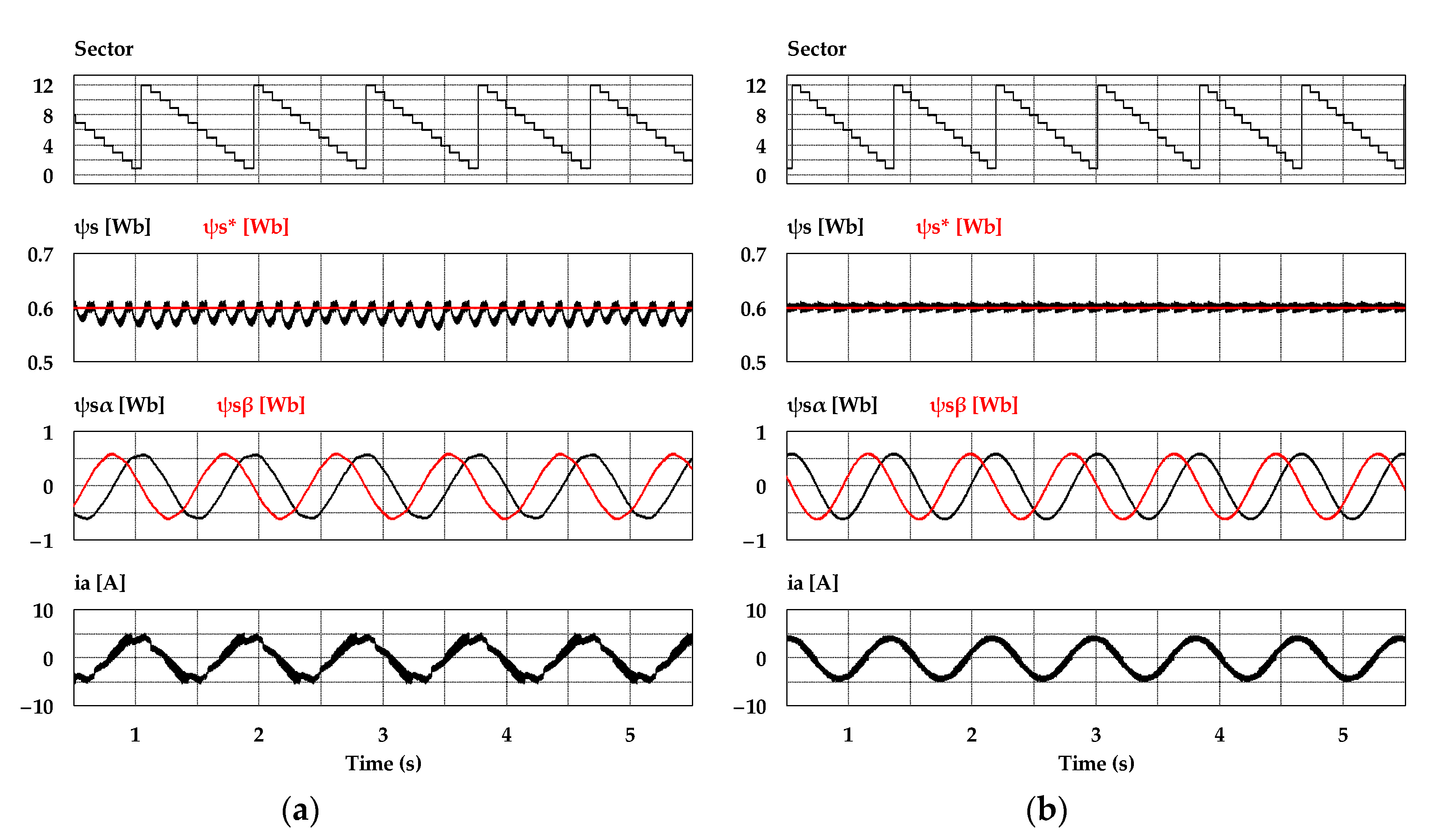
6. Simulation Results

To verify the effectiveness of the proposed DTC-SFRS, simulation using the PSIM tool was carried out using real experimental settings, where sampling time was set to 70 μs. The parameters of the IM motor are listed in Table 2. The band size of HTR was set to be 10% of the rated torque (i.e., ΔTe/2 = 2 Nm), whereas the stator flux band was 0.0015 Wb. Figure 7 shows the simulation results of the sectors, stator flux, stator flux α-β components, and stator current when the IM operates at 50 r/min in the forward direction with a light mechanical load of 4 Nm. It can be noticed that the proposed DTC-SFRS can regulate the ψs, which resulted in pure sinusoidal waveforms of both stator flux α-β components and stator current. Similarly, the proposed DTC-SFRS maintained its effectiveness, even when the IM operates in the reverse direction at 50 r/min with the same torque load as shown in Figure 8. Overall, the proposed DTC-SFRS reduced the THD of both stator flux α-β components and stator current, which lead to the smoother and more stable operation of the IM particularly at very low-speed.

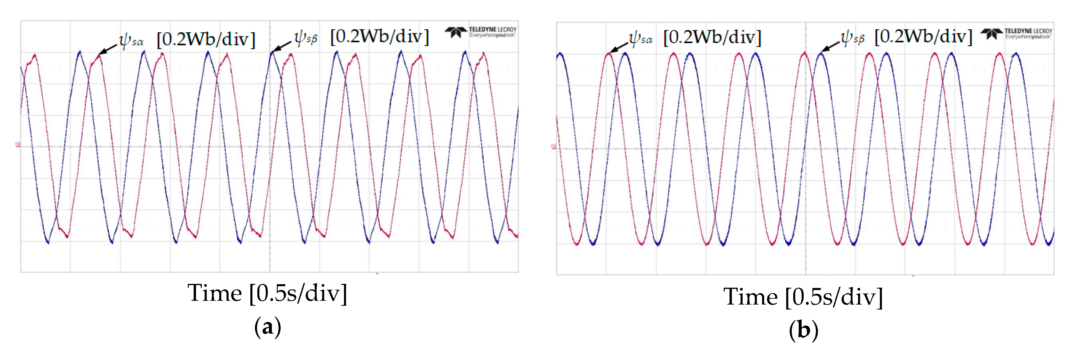
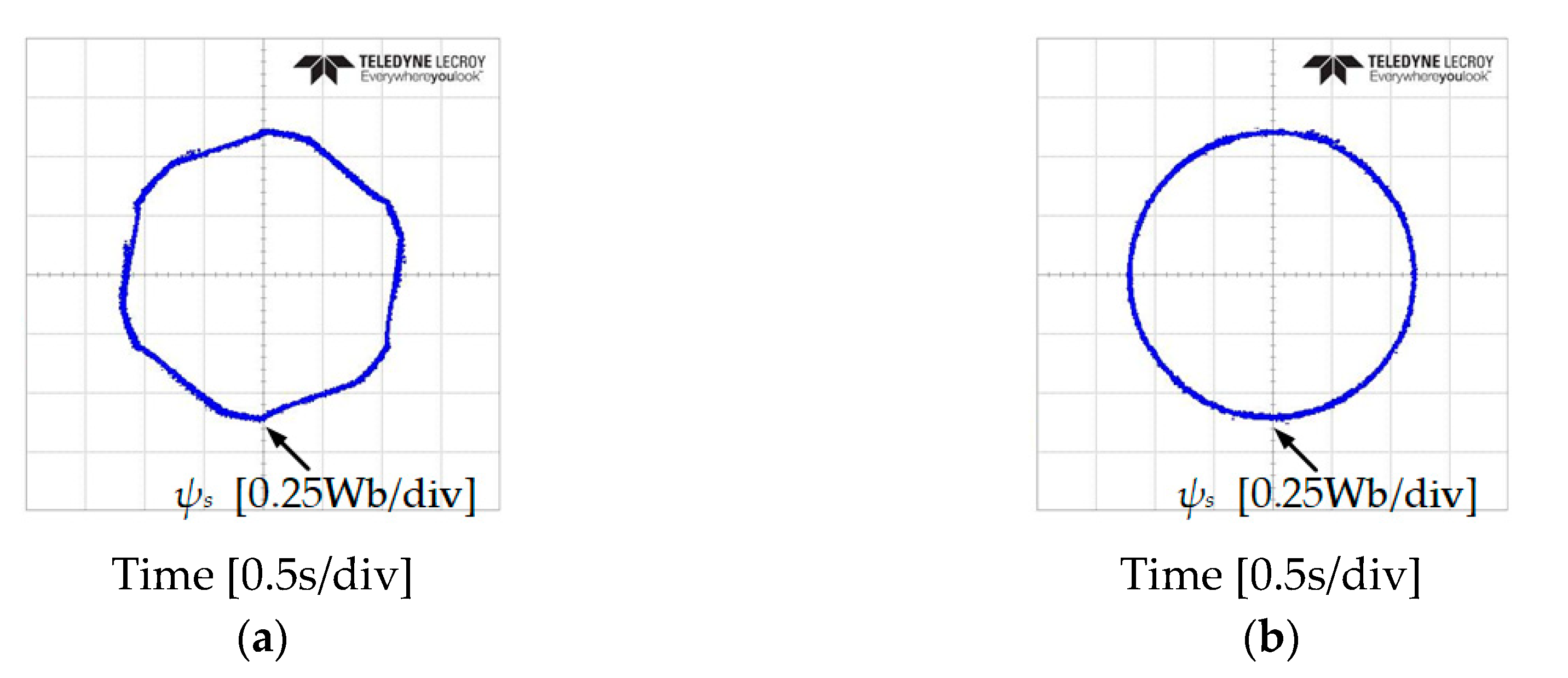
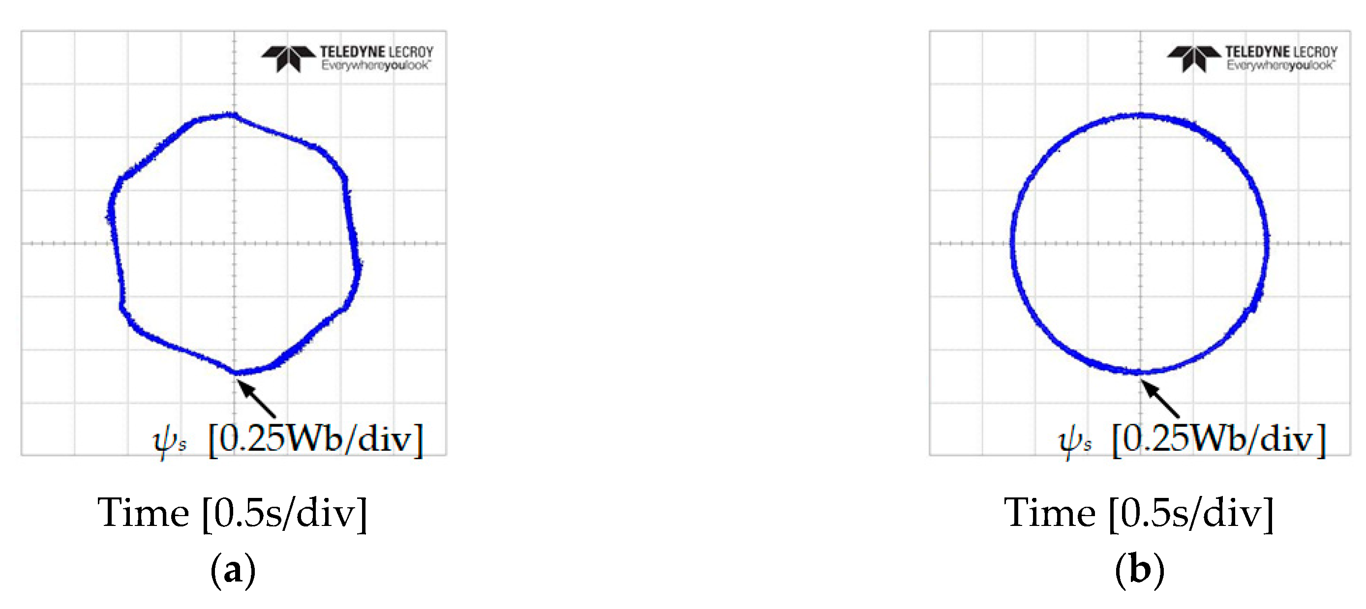
7. Experimental Results

To validate the effectiveness of the proposed DTC-SFRS, the experimental setup shown in Figure 9 was used. It consisted of a TMS320F28335 DSP control board and a three-level NPC inverter equipped with IGBTs. A 5.5 kW mechanical load was connected to the IM and it was controlled by a Yaskawa inverter. To maintain the same operational conditions as the simulation, the sampling time was set to 70 μs and the same parameters of the IM motor, which is listed in Table 2, were considered. In this section, the results will show the problem associated with the classical DTC at low-speed and how its poor performance was affecting the corresponding waveform of the stator current, which resulted in high THD. The results will be divided into two subsections; steady-state and transient-state operations. Each subsection will analyze and compare the classical DTC and proposed SFRS based DTC for both forward and reverse operations of the IM fed by the three-level NPC inverter. In addition, a full set of analytical data was presented to show the robustness of the proposed SFRS based DTC method in minimizing the stator flux-droop at low-speed. Moreover, the THD of the stator current was significantly reduced.

7.1. Steady-State Operation

It was important to note that the experiments were carried for low-speed operation of IM, where the stator flux magnitude significantly droops.
Figure 10 and Figure 11 show the experimental results of stator flux, sectors, and stator current when the IM operates at 50 r/min in both rotational directions with 4 Nm of load torque. It can be observed that the proposed DTC-SFRS can keep the stator flux regulated regardless of the rotational direction of the IM by replacing the zero voltage vectors with the reverse active voltage vector in the subsector, which is affected by stator flux-droop. Moreover, the responses of stator flux α-β components are shown in Figure 12 and Figure 13 for both forward and reverse operations of the IM, respectively. It is evident that the proposed DTC-SFRS can minimize the THD of the stator flux α-β components that result in pure sinusoidal waveforms.
In addition, an investigation of the stator flux trajectory response has been done to verify the problem at low-speed of IM at 50 and −50 r/min, as shown in Figure 14 and Figure 15. It is shown that the classical DTC has 6 subsectors where the magnitude of the stator flux droops. The proposed DTC-SFRS managed to solve the problem unregulated stator flux at these particular subsectors owning to the simple algorithm used in this topology, which resulted in a pure circular shape trajectory of the stator flux.

7.2. Transient-State Operation

Figure 16 and Figure 17 show the results of stator flux, sectors, and stator current when the IM speed stepped down from 150 r/min to at 50 r/min for the forward operation and from −150 r/min to −50 r/min with a light load torque of 4 Nm. It can be observed that the problem of the stator flux-droop was significant at very low-speed of the IM, where the effect of the stator resistance became high. By using the proposed DTC-SFRS, the stator flux is regulated at all speed regions including the critical very low-speed of the IM. Furthermore, an improvement has been achieved using the proposed DTC-SFRS on the stator current waveform with less THD as compared to the classical DTC.
Finally, the analytical data of the stator flux error and stator current THD is presented in Figure 18. It is shown that the proposed DTC-SFRS successfully manages to maintain the stator flux error within the bands even at zero speed where the stator flux magnitude droops by 0.21 Wb. Moreover, the proposed DTC-SFRS reduced the THD of stator current to less than 10% over various speed regions including zero speed to have a robust control of the IM for advanced industrial applications.

8. Conclusions

In this paper, a simple flux regulation strategy (SFRS) is proposed to improve the low-speed performance of DTC for IM drives fed by three-level NPC inverter. The proposed DTC-SFRS method shows excellent performance for both steady-state and transient-state operations of IM. In addition, the responses of stator current and flux have been improved by regulating the stator flux of the IM at very low-speed. The main advantage of the proposed method is its simple implementation while retaining the feature of the classical DTC. The effectiveness of the proposed method was demonstrated by the simulation and experimental results.

Author Contributions

Conceptualization, methodology, and formal analysis, S.S.H. and I.M.A.; experimental validation, S.S.H.; writing—original draft preparation, S.S.H.; writing—review and editing the final manuscript, S.S.H., I.M.A., and K.-B.L.; resources and supervision, K.-B.L. All authors have read and agreed to the published version of the manuscript.

Funding

This research was supported in part by the Korea Electric Power Corporation (KEPCO) under Grant R19XO01-20, and in part by the Railroad Technology Research Program (RTRP), funded by the Ministry of Trade, Industry, and Energy (MOTIE) under Grant 19RTRP-B146008-02.

Acknowledgments

The authors would like to thank Power Electronics Laboratory colleagues of the Electrical and Computer Engineering Department, Ajou University, South Korea.

Conflicts of Interest

The authors declare no conflict of interest.

References

  1. Chan, T.-F.; Shi, K. Applied Intelligent Control of Induction Motor Drives; Wiley: Hoboken, NJ, USA, 2011. [Google Scholar]
  2. Hannan, M.A.; Ali, J.A.; Jern, K.P.; Mohamed, A.; Lipu, M.S.H.; Hussain, A. Switching techniques and intelligent controllers for induction motor drive: Issues and recommendations. IEEE Access 2018, 6, 47489–47510. [Google Scholar] [CrossRef]
  3. Takahashi, I.; Noguchi, T. A new quick-response and high efficiency control strategy of an induction motor. IEEE Trans. Ind. Appl 1986, IA–22, 820–827. [Google Scholar] [CrossRef]
  4. Alsofyani, I.M.; Kim, K.Y.; Lee, S.S.; Lee, K.-B. A Modified Flux Regulation Method to Minimize Switching Frequency and Improve DTC-Hysteresis-Based Induction Machines in Low-Speed Regions. IEEE J. Emerg. Sel. Top. Power Electron. 2019, 7, 2346–2355. [Google Scholar] [CrossRef]
  5. Lee, K.-B.; Song, J.H.; Choy, I.; You, J.Y. Improvement of low-speed operation performance of DTC for three-level inverter-fed induction motors. IEEE Trans. Ind. Electron. 2001, 48, 1006–1014. [Google Scholar]
  6. Yuan, T.; Wang, D. Performance Improvement for PMSM DTC System through Composite Active Vectors Modulation. Electronics 2018, 7, 263. [Google Scholar] [CrossRef] [Green Version]
  7. Lee, K.-B.; Blaabjerg, F. An improved DTC-SVM method for sensorless matrix converter drives using an overmodulation strategy and a simple nonlinearity compensation. IEEE Trans. Ind. Electron. 2007, 54, 3155–3166. [Google Scholar] [CrossRef]
  8. Lee, J.S.; Choi, C.-H.; Seok, J.-K.; Lorenz, R.D. Deadbeat–direct torque and flux control of interior permanent magnet synchronous machines with discrete time stator current and stator flux linkage observer. IEEE Trans. Ind. Appl. 2011, 47, 1749–1758. [Google Scholar] [CrossRef]
  9. Lascu, C.; Trzynadlowski, A.M. Combining the principles of sliding mode, direct torque control, and space-vector modulation in a high-performance sensorless AC drive. IEEE Trans. Ind. Appl. 2004, 40, 170–177. [Google Scholar] [CrossRef]
  10. Lee, H.; Nguyen, H.M.; Chun, T. Implementation of Direct Torque Control Method using Matrix Converter Fed Induction Motor. J. Power Electron. 2008, 8, 74–80. [Google Scholar]
  11. Liu, G.; Yang, Y.; Chen, Q. Virtual Signal Injected MTPA Control for DTC Five-Phase IPMSM Drives. J. Power Electron. 2019, 19, 956–967. [Google Scholar]
  12. Deng, Y.; Liang, Z.; Xia, P.; Zuo, X. Improved Speed Sensorless Vector Control Algorithm of Induction Motor Based on Long Cable. J. Electr. Eng. Technol. 2019, 14, 219–229. [Google Scholar] [CrossRef] [Green Version]
  13. Alsofyani, I.M.; Idris, N.R.N.; Lee, K.-B. Impact of Observability and Multi-objective Optimization on the Performance of Extended Kalman Filter for DTC of AC Machines. J. Electr. Eng. Technol. 2019, 14, 231–242. [Google Scholar] [CrossRef]
  14. Rodriguez, J.; Kazmierkowski, M.P.; Espinoza, J.R.; Zanchetta, P.; Abu-Rub, H.; Young, H.A.; Rojas, C.A. State of the Art of Finite Control Set Model Predictive Control in Power Electronics. IEEE Trans. Ind. Inform. 2013, 9, 1003–1016. [Google Scholar] [CrossRef]
  15. Du, M.; Tian, Y.; Wang, W.; Ouyang, Z.; Wei, K. A Novel Finite-Control-Set Model Predictive Directive Torque Control Strategy of Permanent Magnet Synchronous Motor with Extended Output. Electronics 2019, 8, 388. [Google Scholar] [CrossRef] [Green Version]
  16. Wang, X.; Zhao, J.; Wang, Q.; Li, G.; Zhang, M. Fast FCS-MPC-Based SVPWM Method to Reduce Switching States of Multilevel Cascaded H-Bridge STATCOMs. J. Power Electron. 2019, 19, 244–253. [Google Scholar]
  17. Bak, Y.; Jang, Y.; Lee, K.-B. Torque Predictive Control for Permanent Magnet Synchronous Motor Drives Using Indirect Matrix Converter. J. Power Electron. 2019, 19, 1536–1543. [Google Scholar]
  18. Zhou, Y.; Li, H.; Zhang, H.; Mao, J.; Huang, J. Model Free Deadbeat Predictive Speed Control of Surface-Mounted Permanent Magnet Synchronous Motor Drive system. J. Electr. Eng. Technol. 2019, 14, 265–274. [Google Scholar] [CrossRef]
  19. Li, Y.; Wang, C.; Hu, H. Predictive control of torque and flux of induction motor drives. In Proceedings of the 2005 International Conference on Power Electronics and Drives Systems (PEDS), Kuala Lumpur, Malaysia, 28 November–1 December 2005; pp. 67–71. [Google Scholar]
  20. Wang, F.; Zhang, Z.; Davari, S.A.; Fotouhi, R.; Khaburi, D.A.; Rodríguez, J.; Kennel, R. An Encoderless Predictive Torque Control for an Induction Machine with a Revised Prediction Model and EFOSMO. IEEE Trans. Ind. Electron. 2014, 61, 6635–6644. [Google Scholar] [CrossRef]
  21. Habibullah, M.; Lu, D.D.-C. A Speed-Sensorless FS-PTC of Induction Motors Using Extended Kalman Filters. IEEE Trans. Ind. Electron. 2015, 62, 6765–6778. [Google Scholar] [CrossRef]
  22. Cho, Y.; Bak, Y.; Lee, K.-B. Torque-Ripple Reduction and Fast Torque Response Strategy for Predictive Torque Control of Induction Motors. IEEE Trans. Power Electron. 2018, 33, 2458–2470. [Google Scholar] [CrossRef]
  23. Chen, W.; Zhao, Y.; Zhou, Z.; Yan, Y.; Xia, C. Torque Ripple Reduction in Three-Level Inverter-Fed Permanent Magnet Synchronous Motor Drives by Duty-Cycle Direct Torque Control Using an Evaluation Table. J. Power Electron. 2017, 17, 368–379. [Google Scholar] [CrossRef] [Green Version]
  24. Vafaie, M.H.; Dehkordi, B.M.; Moallem, P.; Kiyoumarsi, A. Minimizing Torque and Flux Ripples and Improving Dynamic Response of PMSM Using a Voltage Vector With Optimal Parameters. IEEE Trans. Ind. Electron. 2016, 63, 3876–3888. [Google Scholar] [CrossRef]
  25. Cho, Y.; Lee, K.-B.; Song, J.-H.; Lee, Y. -I. Torque-ripple minimization and fast dynamic scheme for torque predictive control of permanent-magnet synchronous motors. IEEE Trans. Power Electron. 2015, 30, 2182–2190. [Google Scholar] [CrossRef]
  26. Mohan, D.; Zhang, X.; Foo, G.H.B. Three-Level Inverter-Fed Direct Torque Control of IPMSM with Constant Switching Frequency and Torque Ripple Reduction. IEEE Trans. Ind. Electron. 2016, 63, 7908–7918. [Google Scholar] [CrossRef]
  27. Naganathan, P.; Srinivas, S.; Ittamveettil, H. Five-level torque controller-based DTC method for a cascaded three-level inverter fed induction motor drive. IET Power Electron. 2017, 10, 1223–1230. [Google Scholar] [CrossRef]
  28. Lee, K.-B.; Lee, J.S. Reliability Improvement Technology for Power Converters; Springer: Singapore, 2017. [Google Scholar]
  29. Lee, K.-B.; Song, J.-H.; Choy, I.; Yoo, J.Y. Torque ripple reduction in DTC of induction motor driven by three-level inverter with low switching frequency. IEEE Trans. Power Electron. 2002, 17, 255–264. [Google Scholar]
  30. Alsofyani, I.M.; Bak, Y.; Lee, K.-B. Fast Torque Control and Minimized Sector-Flux Droop for Constant Frequency Torque Controller based-DTC of Induction Machines. IEEE Trans. Power Electron. 2019, 34, 12141–12153. [Google Scholar] [CrossRef]
  31. Hakami, S.S.; Alsofyani, I.M.; Lee, K.-B. Improved Constant Switching Frequency Torque Regulator based DTC of IM Fed by 3L-NPC Inverter for Wide Speed Region. In Proceedings of the 2019 IEEE Conference on Energy Conversion (CENCON), Yogyakarta, Indonesia, 16–17 October 2019; pp. 42–46. [Google Scholar]
Figure 1. Circuit topology of three-level neutral-point clamped (NPC) inverter.
Electronics 09 00077 g001
Figure 2. Space vector representation of three-level NPC inverter.
Electronics 09 00077 g002
Figure 3. Complete structure of a classical DTC.
Electronics 09 00077 g003
Figure 4. Hysteresis regulators: (a) Five-level hysteresis torque regulator (HTR); (b) two-level HFR.
Electronics 09 00077 g004
Figure 5. Sector flux-droop of the induction motor (IM) at low-speed: (a) Forward direction; (b) reverse direction.
Electronics 09 00077 g005
Figure 6. The complete structure of the proposed DTC-simple flux regulation strategy (SFRS).
Electronics 09 00077 g006
Figure 7. Sectors, stator flux, α-β components of stator flux and stator current responses of five-level HTR at 50 r/min in the forward direction of IM: (a) Classical DTC; (b) proposed DTC-SFRS.
Electronics 09 00077 g007
Figure 8. Sectors, stator flux, α-β components of stator flux and stator current responses of five-level HTR at 50 r/min in reverse direction of IM: (a) Classical DTC; (b) proposed DTC-SFRS.
Electronics 09 00077 g008
Figure 9. Experimental setup.
Electronics 09 00077 g009
Figure 10. Stator flux, sectors and current responses of five-level HTR at 50 r/min in forward direction of IM: (a) classical DTC; (b) proposed DTC-SFRS.
Electronics 09 00077 g010
Figure 11. Stator flux, sectors and current responses of five-level HTR at 50 r/min in reverse direction of IM: (a) classical DTC; (b) proposed DTC-SFRS.
Electronics 09 00077 g011
Figure 12. α-β components of stator flux responses of five-level HTR at 50 r/min in forward direction of IM: (a) classical DTC; (b) proposed DTC-SFRS.
Electronics 09 00077 g012
Figure 13. α-β components of stator flux responses of five-level HTR at 50 r/min in reverse direction of IM: (a) classical DTC; (b) proposed DTC-SFRS.
Electronics 09 00077 g013
Figure 14. Stator flux trajectory response of five-level HTR at 50 r/min in forward direction of IM: (a) classical DTC; (b) proposed DTC-SFRS.
Electronics 09 00077 g014
Figure 15. Stator flux trajectory response of five-level HTR at 50 r/min in reverse direction of IM: (a) classical DTC; (b) proposed DTC-SFRS.
Electronics 09 00077 g015
Figure 16. Speed transient from 150 r/min to 50 r/min: stator flux, sectors and current responses of five-level HTR in forward direction of IM: (a) classical DTC; (b) proposed DTC-SFRS.
Electronics 09 00077 g016
Figure 17. Speed transient from 150 r/min to 50 r/min: stator flux, sectors and current responses of five-level HTR in reverse direction of IM: (a) classical DTC; (b) proposed DTC-SFRS.
Electronics 09 00077 g017
Figure 18. Effectiveness of the proposed method at different speed operations: (a) Minimizing stator flux-droop; (b) reducing stator current THD.
Electronics 09 00077 g018
Table 1. Switching table for the direct torque controller (DTC) fed by a three-level NPC inverter.
ψs StatusTe StatusSec 1aSec 1bSec 2aSec 2bSec 3aSec 3bSec 4aSec 4bSec 5aSec 5bSec 6aSec 6b
+2V8V3V9V4V10V5V11V6V12V1V7V2
+1V14V15V15V16V16V17V17V18V18V13V13V14
10V0V0V0V0V0V0V0V0V0V0V0V0
−1V17V18V18V13V13V14V14V15V15V16V16V17
−2V5V11V6V12V1V7V2V8V3V9V4V10
+2V7V2V8V3V9V4V10V5V11V6V12V1
+1V13V14V14V15V15V16V16V17V17V18V18V13
00V0V0V0V0V0V0V0V0V0V0V0V0
−1V18V13V13V14V14V15V15V16V16V17V17V18
−2V6V12V1V7V2V8V3V9V4V10V5V11
Table 2. Induction motor specifications.
ParameterValue
Nominal power3.7 kW
Nominal torque20.36 Nm
Nominal speed1750 r/min
Nominal current8.28 A
Reference flux0.6 Wb
Number of pole-pairs2
Rotor inductance146.2 mH
Rotor resistance1.225 Ω
Stator inductance146.2 mH
Stator resistance0.934 Ω
Mutual inductance139.52 mH

