Abstract
This paper presents a new design of a fifth order bandpass waveguide filter with Chebyshev response which operates in the X-band at 10 GHz center frequency. By using a complementary split ring resonator (CSRR) upper and lower sections that are placed on the same transverse plane and are not on the same parallel line, CSRR sections are shifted from each other. A simple model of lumped elements RLC is introduced and calculated as well. The model of the proposed bandpass waveguide filter is synthesized and designed by using computer simulation technology (CST). Hereafter, by selecting proper physical parameters and optimizing the overall CSRR geometrical dimensions by taking into consideration the coupling effect between resonators, a shortened length of the overall filter, and a wider bandwidth over the conventional one are obtained. As a result, the proposed filter is compared with the conventional bandpass waveguide filter that is coupled by inductive irises with Chebyshev response, in addition to other studies that have used the metamaterial technique. The proposed filter reduces the overall physical length by and enhances the bandwidth up to .
1. Introduction
Waveguides are in general hollow metallic wave guiding structures used as filters, couplers, combiners, and amplifiers in various microwave and millimeter wave applications due to their less power consumption and high power handling capacity [1]. Recent advents in wireless communication applications have enormously increased the demand on antennas and filters with improved frequency selectivity as well as decreased overall physical size. For instance, such a demand results in various forms of designs and implementations of waveguide filters with improved characteristics of sharpness, bandwidth, and physical size [2,3,4].
Filters are components designed with the purpose of selecting or transmitting signals over specified band and rejecting signals over the other bands. Although various forms of microwave filters are available in the literature, they all have the same common point by which their performance is evaluated using the distributed network concept, assuming that they usually consist of periodic structures exhibiting passband and stopband characteristics in various frequency bands [1]. A variety of waveguide filters with different characteristics of low insertion loss, high Q factor, and sharp frequency selectivity have been proposed for various applications [5,6,7,8]. For example, inductive irise-coupled resonators are implemented into waveguide structures to have a Chebyshev response with N-poles [9]. In addition, stepped-impedance resonators are employed in the design of an X-band waveguide filter at 10 GHz to have superior filter characteristics [10]. Furthermore, a co-planar waveguide filter by using the bended stub and folded structure at GHz [11], E-plane waveguide filter with periodically loaded resonators [12,13,14], and T-shaped resonators with reduced size [15] are also implemented. On the other hand, the introduction of the substrate-integrated waveguide technique [16] has lead to the emergence of many microwave filters with quarter wavelength resonator based on impedance and admittance inverters’ method [17]. An aperture engraved in the middle common ground of the vertically stacked cavities [18] and U-shape slots on substrate integrated waveguide (SIW) with low temperature co-fired ceramic (LTCC) [19] at 40 GHz and 3D printed inserted into waveguide filter at 10 GHz [20] are implemented. In a recent study, two quarter-wavelength stepped-impedance resonators are realized to suppress the effect of a third harmonic in a wideband bandpass filter design being presented [21].
After the implementation of engineered materials [22] coined as metamaterials (MMs) based on the study of Veselago [23], a new era has been opened in the design and implementation of microwave filters due to their unique, unnatural, and exotic electromagnetic properties. Split ring resonators (SRRs) played a vital rule in the design of microwave applications like filters. Because of resonance structures of (SRRs) and their resonance behavior, they can be used for miniaturizing overall microwave devices. Waveguides embedded with metamaterial in various forms with diverse electromagnetic properties are designed to reduce the size of the filter [24]; to have a narrow-band filter in a rectangular waveguide using complementary split ring resonator (CSRR) has been proved, but the authors didn’t mention the type of response or the final size of the proposed filter [25]. Using different models of CSRRs inside rectangular waveguide to design bandpass filter for single and dual mode has been demonstrated [26], and a compact dual-band waveguide bandstop filter using double SRR structure is designed [27].
In addition to these studies, gradually, metamaterials have spread out in many syntheses and designs to improve performance whether cutoff frequency or bandwidth of filter by using coupled split ring resonators (SRRs) and a negative image of split ring resonator CSRRs [28,29,30,31,32,33] are proposed and designed. However, previous studies have discussed and focused on dimensions of meta-resonators without mentioning or discussing shifts between upper and lower rings. Due to the shift property between CSRR rings, reaching the center frequency in a faster way is expected.
In [34], the authors have designed and simulated a three poles Chebyshev bandpass waveguide filter by using single CSRR in the X-band at center frequency GHz. Although the methodology used in this article is straightforward due to the usage of a single resonator, it gives a narrow bandwidth 500 MHz and is not able to control the bandwidth or the selectivity of filter well; particularly, they have implemented two filters with a different number of poles and given the same narrow bandwidth; furthermore, they didn’t mention the overall physical size of the proposed filter. Whilst the authors in [33] have proposed a unit cell of CSRR and tuned it at GHz center frequency without mentioning the type of filter or the number of filter’s poles, they have just implemented their resonator based on optimization of its physical dimensions to get a desired center frequency with 2 GHz passband. In addition, their method has just depended on the changing physical dimensions of CSRR itself.
Here, in our work, in order to improve the miniaturization of Chebyshev bandpass waveguide filter based metamaterials over a conventional filter at 10 GHz center frequency with five resonators, and to improve its selectivity and insertion loss alongside bandwidth as well. Simple double symmetric unit cells with electric coupling between CSRRs which are engraved from the center to facilitate and tune the resonating frequency at 10 GHz are used. The CSRRs have been designed with shifting between the upper and lower sections. The shifting between two CSRRs—right or left from each other—means the changing of electric coupling between them, and, due to this change in coupling, the center frequency will be affected directly with respect to this shifting. In this work, with the change in CSRR’s physical dimensions besides the shift between two loops, the optimal waveguide filter is obtained in a systematic manner as it will be shown in Section 3.1. Cutoff frequency, Q factor, and S-parameters are studied and calculated by using computer simulation technology (CST), and a circuit simulator is used to implement and simulate a lumped element bandpass filter as well.
Unlike the conventional filters, the proposed filter is designed based on the metamaterial resonators’ technology that are coupled directly without H-plane waveguide junctions between resonators that give the design important factors, especially for telecommunication applications such as compact size, simple structure, and wide bandwidth. Thus, according to these features, the proposed filter could be employed inline with low noise amplifier (LNA) for X-band receiver circuits which works at 10 GHz center frequency ( GHz– GHz) to suppress the unwanted signal band, and waveguide size is critical in such circuits as well [35]. In addition, the proposed filter could be employed inline with X-band power amplifier at 10 GHz center frequency to achieve the maximum power and extend the desired bandwidth [36]. An X-band RADAR transceiver module that works at the same frequency band ( GHz– GHz) could be inserted with high selectivity and a high quality factor [28].
2. Fundamentals of Waveguide Resonators
The working principles of microwave filters operating at high frequencies are very similar to those of lumped elements series or parallel resonators in circuit theory [1]. Microwave resonators are constructed by enclosing (short circuiting) both ends of waveguide structures as shown in Figure 1a by metallic walls. For instance, Figure 1b shows the geometry of a rectangular waveguide resonator () with length d shorted at both ends and . Here, it is assumed that waveguide is extending in the z-axis. Electromagnetic energy (in the electric and magnetic fields) is stored within the box enclosure as shown in Figure 2, and it reaches its maximum at good coupling, and it dissipates power in the metallic walls and/or within the filling dielectric material , where is a medium’s relative permittivity.
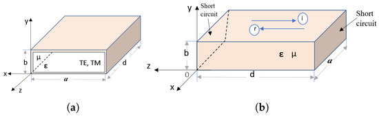
Figure 1.
(a) rectangular waveguide ; (b) rectangular cavity, shorted and perfect electric conductor (PEC) for all sides .
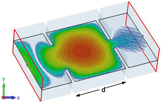
Figure 2.
Electromagnetic energy stored in the rectangular waveguide resonator for X-band WR-90 with dimension a = 22.86 mm and b = 10.16 mm at center frequency 10 GHz with length d.
By applying the Poynting vector in a cavity in which applying conditions of modes, power will be purely imaginary, and time averaged power density (real part) will be zero. This means that there is no real power in/out the cavity will be transferred. However, the imaginary part means that there is a stored energy in electromagnetic fields inside the cavity [1]. Meanwhile, the quality factor (Q) is an important parameter and should be taken into consideration once design of the microwave filter is needed. The quality factor measures the strong coupling either in electric (aperture) or magnetic origin (loop) between resonators; in other words, it measures the losses in the resonator. Q is alternatively defined as the ratio of a resonator’s center frequency to its 3-dB bandwidth (means bandwidth of the range of frequencies for which the energy is at least half its peak value) and given by the formula [1]. However, the external coupling factor (k factor) between resonators is defined by
where and are the lower and higher frequencies of the filter, and the adjacent cavities.
Under the condition that a cavity is lossless, transverse electric field intensity can be derived as [1]:
where is the transverse variation of mode, and are, respectively, the arbitrary amplitudes of the forward and backward traveling waves, and is the phase constant of wave. Application of boundary conditions on the side walls and of the cavity results in
where is the wave number of the material filling the waveguide, and are the permeability and permittivity of the filled material, and m and n denote the number of half-sine (or cosine) variations in x and y directions. Application of boundary conditions at the front and rear faces of the enclosed waveguide cavity at yields the well-known following resonant frequency
where l denotes the number of half-sine (or cosine) variations on the z-axis. Figure 3a shows the parameter of the resonator at 10 GHz resonant frequency when the port 2 in Figure 2 is weak, and Figure 3b shows the real reference impedance to the same resonator at 10 GHz.
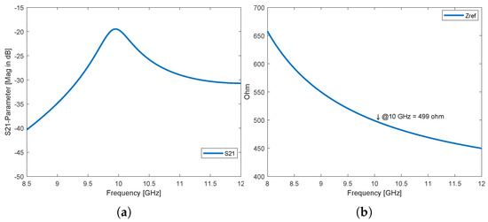
Figure 3.
(a) S21 parameter of waveguide resonator, and (b) reference Impedance real part of waveguide resonator.
3. Design and Simulation
In the late 1960s, Veselago has paved the way for using artificial materials (unnatural material) [23] with negative and . Considerably later, the evidence of medium with simultaneous negative and was demonstrated experimentally [22]. As demonstrated in [25], one can use CSRR to design a compact waveguide filter by an engraving metallic sheet. Here, in this paper, a double ring meta-resonator engraved from the center of CSRR as shown in Figure 4a to reduce the physical size of the waveguide filter that is coupled by inductive or capacitive irises has been used. The engraved rings on the copper plane are not mutually aligned to each other, thus the upper ring and the lower ring are not on the same vertical line (shifted). Nevertheless, the shifting of rings plays another role besides selecting proper CSRR physical dimensions to move the resonant frequency as desired. Based on the coupling phenomena, shifting changes the coupling between two rings, so that selecting a good shift with a proper physical dimension of CSRR gives a quick response at desired resonant frequency as shown in the response in Figure 4b.
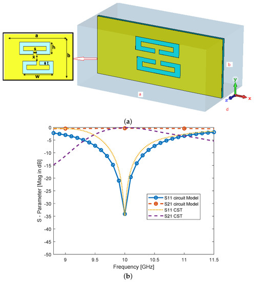
Figure 4.
(a) rectangular meta-resonator design; (b) S-parameter response of waveguide meta-resonator and which is compared by using (CST) and a circuit simulator.
As shown in Figure 4, computer simulation technology (CST) is used to simulate rectangular waveguide resonator which initial length is at 10 GHz for X-band applications with lower cutoff frequency GHz, higher cutoff frequency GHz, and dB passband ripple. In addition, using substrate material (RT/Duroid) with a thickness of 0.5 mm, permittivity constant , and appropriate mesh density selection 10 steps per wavelength with 20 min number of steps are selected. Annealed copper (lossy material) with conductivity [S/m], thickness 30 m is chosen for metallic layer, and impedance at resonant frequency as shown in Figure 3b.
The microwave resonant circuits in high frequency behave as elements in low frequency circuits (including ohmic losses) that can be excited by external magnetic source. In other words, to obtain lumped elements model from distributed model, values of components that are calculated using Equations (5)–(7) as proposed in [26] will be used. The equivalent lumped elements model for the proposed meta-resonator (microstrip) is shown in Figure 5:
where is angular frequency (rad/s), bandwidth at specific frequency, port impedance, and is S-parameter at considered resonant frequency. Based on what is proposed in [26] and the definition of circuit R, L, and C parameters, shown in Figure 5, and, because of symmetry between two CSRRs, the values are obtained at 10 GHz resonant frequency by using Equations (5)–(7): , GHz, , pF, nH.
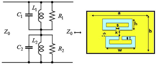
Figure 5.
Rectangular meta-resonator and its simple lumped model RLC circuit.
3.1. Bandpass Waveguide Filter Using Symmetric CSRR
Up to now, a single waveguide meta-resonator by using CSRR and according to simulation results of meta-resonator as shown in Figure 4b has been analyzed, it can be noticed that the variation of parameters , w, and t introduce a shift of the resonant frequency and effect on bandwidth according to the main values of the same Figure 4a ( GHz and GHz), as listed in Table 1 and already has been shown in Figure 6, Figure 7, Figure 8, Figure 9, Figure 10 and Figure 11. Changing the width (s) of the engraved center of two loops leads to changing resonant frequency according to the variation coupling capacitance as shown in Figure 7 and, once engraving width increases, the resonant frequency increases as well. Figure 8 shows the variations of vertical separation (x) between the two loops and its effect on the change electrical coupling between loops, as a result of increasing the separation, the resonant frequency will be decreased and will then move to the left. Figure 9 shows an increase in the height (h) of the loop, decreasing the resonant frequency and moving to the left. In Figure 10, alternation in the line width of loops has a direct effect on the resonant frequency, decreases (t) parameter, and increases resonant frequency according to a variation of currents that moves along a path of the loops. As well as changing the width of the loops (upper and lower), the bandwidth and the resonant frequency change accordingly, and an increase in the (w) parameter decreases the resonant frequency as shown in Figure 11. For the waveguide filter design, WR- 90 standard, , mm, mm, and Chebyshev response are used here. The Chebyshev response that exhibits the equal-ripple passband and maximally flat stopband. The alternation of the Chebyshev response as well as changing the bandwidth and sharpness of a filter could be affected based on the number of its resonators. Meaning that an increase in filter order N will give more sharpness and enhance bandwidth, but, meanwhile, filter design will be more complicated. Figure 12 shows the sharpness of a filter with a Chebyshev response. The sharpness of a filter with a Chebyshev response gets better with an increase in filter order, as expected. The amplitude-squared transfer function that describes this type of response is given by [37]
where is a Chebyshev function of the first kind of order n and the ripple constant is related to a given passband ripple in dB by

Table 1.
The influence of changing parameters of the meta-resonator and its effect on cutoff frequency and bandwidth of a bandpass filter, ← response shifts to the left, → response shifts to the right, and ≈ response doesn’t change.
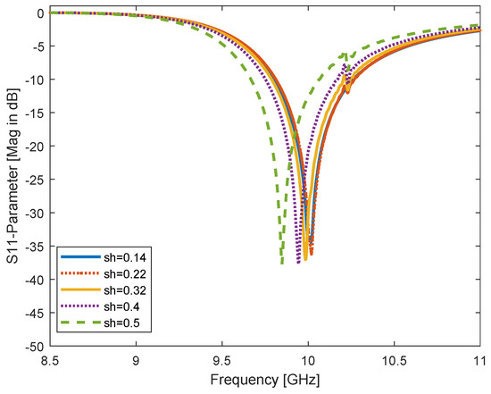
Figure 6.
Alteration of horizontal shift between two CSRR rings (upper and lower loops) sh-parameter for sh = 0.14, 0.22, 0.32, 0.4, and 0.5 mm; resonant frequency is shifted to the left once the sh parameter is increased.
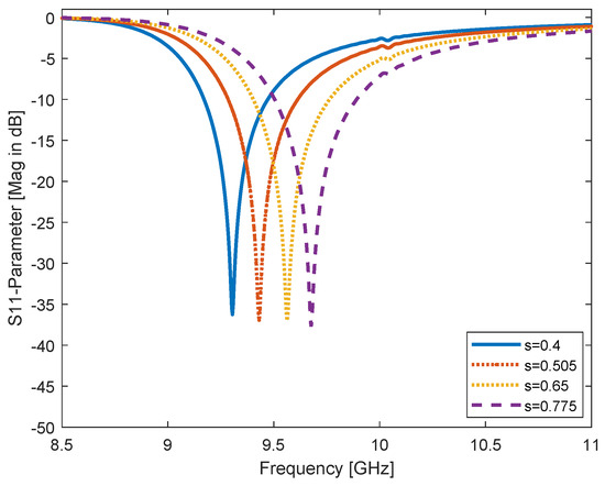
Figure 7.
Engraving the center width of both CSRR rings, the s parameter for both loops and its changing s = 0.4, 0.505, 0.65, and 0.775 mm; the resonant frequency is shifted to the right as a result of changing capacitance.
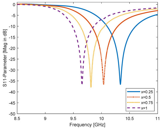
Figure 8.
Alteration of both CSRR rings (upper and lower loops) vertical separation, x parameter for x = 0.25, 0.5, 0.75, and 1 mm, and resonant frequency is shifted to the left according to the coupling effect.
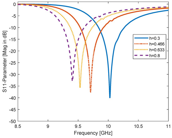
Figure 9.
Alteration of CSRR height, h parameter for h = 0.3, 0.466, 0.633, and 0.8 mm, and the resonant frequency is shifted to the left.
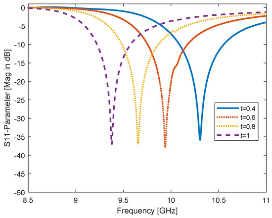
Figure 10.
Changing the line width t parameter of both CSRR rings, for t = 0.4, 0.6, 0.8, and 1 mm, the resonant frequency is shifted to the left and the changing is high in frequency according to this parameter.
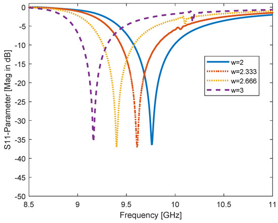
Figure 11.
Alteration of CSRR rings width w parameter and its efffect on resonant frequency w = 2, 2.333, 2.666, and 3 mm; resonant frequency is shifted to the left as well as the bandwidth being decreased.
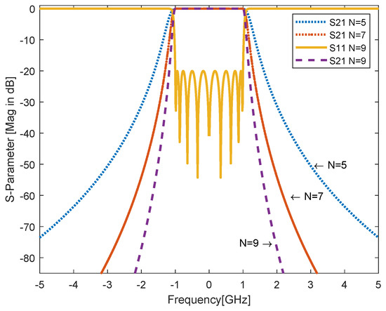
Figure 12.
The alternation of the Chebyshev response as well as changing the bandwidth and the sharpness of a filter could be affected based on the number of its resonators, meaning that an increase of filter order N will give more sharpness and enhance bandwidth for N = 5, 7 and 9.
With increasing value of modes (propagation patterns) in the waveguide, attenuation increases as well (evanescent); particularly, the waveguide acts as a high pass filter and supports all possible modes higher than cutoff frequency, but the attenuation losses are minimum in the lower order mode. Thus, assuming that the dominant pattern of propagation is for the cavity, this means that transverse electric or there are no components of electric field in the direction of propagation , and magnetic components exist in the the same direction of propagation . The proposed waveguide filter has the symmetry modeling of resonators, so this feature reduces the number of variables of design (physical dimensions). The structure of waveguide filter, initially used quarter wavelength distance between adjacent resonators. The gap between the inserted metamaterial and the metallic walls of waveguide is less than 30 m. The procedure used here to design the waveguide bandpass filter is proposed in [38], which depends on the coupling between cascaded meta-resonators. The first waveguide resonator is run and optimized at 10 GHz as shown in Figure 4, the initial length of the waveguide resonator without inserting metamaterial is 40 mm and with inserting metamaterial is 17 mm. After that, another resonator has been inserted within the waveguide, or cascaded with the previous one and so on, as shown in Figure 13. Once the overall waveguide filter is totally designed, the initial response is optimized by using an Interpolated Quasi Newton method to reach the desired filter specifications. The flowchart of the filter design procedure is shown in Figure 14. It is noticed that, at 10 GHz, the return loss is the lesser of dB with insertion loss being close to dB, cutoff at dB, and Q factor is 7563 as shown in Figure 15 and Figure 16.
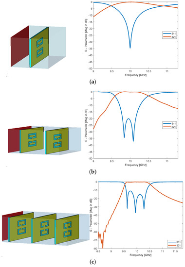
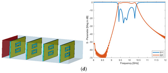
Figure 13.
Design steps of bandpass waveguide filter based on rectangular meta-resonator and its S-parameters for (a) first resonator and its S-parameter; (b) second resonator is added to the first one and its S-parameter; (c) the third resonator is added to both resonators and its S-parameter; (d) the fourth resonator is added in, cascaded to three resonators and its S-parameter.
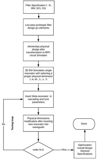
Figure 14.
Flowchart of the waveguide filter design methodology.
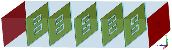
Figure 15.
Final design of the proposed waveguide meta-resonator filter for X-band at resonant frequency 10 GHz.
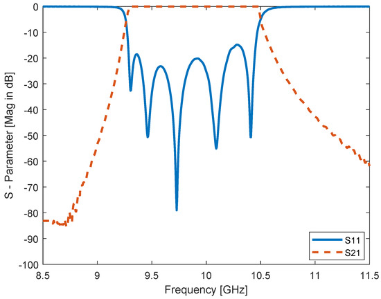
Figure 16.
Optimized final response of the proposed waveguide meta-resonator filter and its S-parameters at dB and dB at center frequency 10 GHz, .
4. Discussion
Based on the initial design specifications of the bandpass filter H-plane, resonant frequency , number of resonators (cavities) N, relative bandwidth , low pass prototype with element values , and insertion loss of filter being assumed, then the conventional resonators are designed to get the desired BPF. To obtain the bandpass filter from a low pass prototype filter with g parameters , , , ,, , and , the frequency transformation method is used here [37] as shown in Figure 17. If the conventional bandpass waveguide filter for X-band application as shown in Figure 18a, with its design method (insertion loss method) as has been proposed in [9,38] that consists of five resonators with inductive apertures (discontinuities), and the proposed metamaterial bandpass waveguide filter (cascaded meta-resonators) as shown in Figure 15 are compared with each other, the use of metamaterial technology shortening the overall physical length of the waveguide filter by and enhancing the bandwidth up to GHz with increasing at 10 GHz will be noticed. In Table 2, a quick comparison between two waveguide filters has been summarized. In Figure 19, both responses of the conventional and the proposed bandpass filters could be seen.
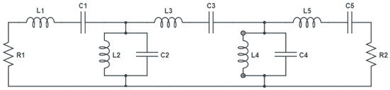
Figure 17.
Circuit model of a symmetrical bandpass filter for the Chebyshev response after transformation from low pass prototype filter, , pF, pF, pF, nH, nH, and nH [37].
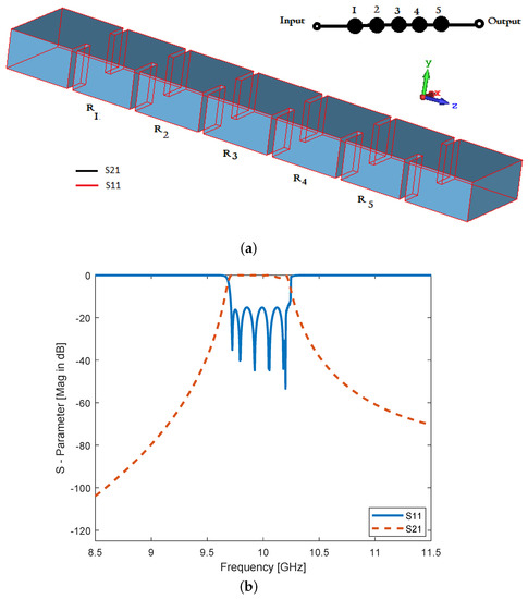
Figure 18.
(a) conventional Bandpass waveguide filter with inductive irises fifth order for WR- 90 standard, , mm, mm, and (b) illustration of S-parameters S11 and S21.
Table 2.
Comparison between conventional waveguide bandpass filter and the metamaterial waveguide filter for the X-band at 10 GHz.
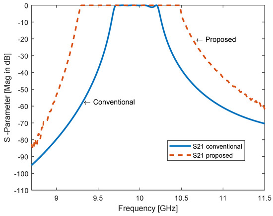
Figure 19.
S-parameter comparison between conventional rectangular waveguide filter with direct waveguide junctions and meta-resonator waveguide filter without waveguide junctions for X-band, . The proposed filter has enhanced the bandwidth to as seen in the figure.
5. Conclusions
In this paper, a simple methodology to control bandwidth and cutoff frequency of waveguide filter is proposed and simulated. Inserting CSRRs in the same plane of transverse in the waveguide filter for X-band applications such as the RADAR communication system and LNA is presented. A CSRR-loaded bandpass waveguide filter with a Chebyshev response using a symmetry structure with a shifted upper or lower ring of CSRR is designed and discussed here. Adding a meta-resonator to another at the same time in the structure, with an initial distance between them, is simulated. A fifth order CSRR-loaded bandpass waveguide filter is designed and simulated by computer simulation technology (CST) along with a circuit simulator as well. The filter’s dimensions are optimized and tuned toward the desired center frequency at 10 GHz, as well as the shifting of upper and/or lower rings from each other. The bandwidth of the proposed bandpass filter increases up to GHz, meaning that the bandwidth of the filter is increased by , and the filter’s size reduced by as well if it was to be compared with the conventional X-band bandpass filter, which is designed by using the insertion loss method at the same center frequency. For future work, the proposed waveguide filter will be employed to design a waveguide diplexer and multiplexer based on the metamaterial technology.
Author Contributions
Conceptualization, M.A.; methodology, M.A.; software, M.A.; Design, M.A., U.C.H; validation, M.A., writing–review and editing, U.C.H.; original draft preparation, M.A.; supervision, U.C.H.; visualization, M.A.; optimization and tuning, M.A. All authors have read and agreed to the published version of the manuscript.
Funding
This research received no external funding.
Conflicts of Interest
The authors declare no conflict of interest.
Abbreviations
The following abbreviations are used in this manuscript:
| MM | Metamaterial |
| SRR | Split Ring Resonator |
| CSRR | Complementary Split Ring Resonator |
| CST | Computer Simulation Technology |
References
- Pozar, D.M. Microwave Engineering; Wiley: Hoboken, NJ, USA, 2012. [Google Scholar]
- Guo, C.; Shang, X.; Lancaster, M.J.; Xu, J. A 3D printed lightweight X-band waveguide filter based on spherical resonators. IEEE Microw. Wirel. Compon. Lett. 2015, 25, 442–444. [Google Scholar] [CrossRef]
- Atia, A.E.; Williams, A.E. Narrow-bandpass waveguide filters. IEEE Trans. Microw. Theory Tech. 1972, 20, 258–265. [Google Scholar] [CrossRef]
- Bonetti, R.R.; Williams, A.E. Application of dual TM modesto triple-and quadruple-mode filters. IEEE Trans. Microw. Theory Tech. 1987, 35, 1143–1149. [Google Scholar] [CrossRef]
- Levy, R.; Cohn, S.B. A history of microwave filter research, design, and development. IEEE Trans. Microw. Theory Tech. 1984, 32, 1055–1067. [Google Scholar] [CrossRef]
- Levy, R.; Snyder, R.V.; Matthaei, G. Design of microwave filters. IEEE Trans. Microw. Theory Tech. 2002, 50, 783–793. [Google Scholar] [CrossRef]
- Hunter, I.C.; Billonet, L.; Jarry, B.; Guillon, P. Microwave filters-applications and technology. IEEE Trans. Microw. Theory Tech. 2002, 50, 794–805. [Google Scholar] [CrossRef]
- Zou, X.; Tong, C.M.; Yu, D.W. Design of an X-band symmetrical window bandpass filter based on substrate integrated waveguide. In Proceedings of the 2011 Cross Strait Quad-Regional Radio Science and Wireless Technology Conference, Harbin, China, 26–30 July 2011; Volume 1, pp. 571–574. [Google Scholar]
- Damou, M.; Nouri, K.; Feham, M.; Chetioui, M. Design and Optimization of Rectangular Waveguide Filter based on Direct Coupled Resonators. Int. J. Electron. Telecommun. 2017, 63, 375–380. [Google Scholar] [CrossRef]
- Morelli, M.; Hunter, I.; Parry, R.; Postoyalko, V. Stopband performance improvement of rectangular waveguide filters using stepped-impedance resonators. IEEE Trans. Microw. Theory Tech. 2002, 50, 1657–1664. [Google Scholar] [CrossRef]
- Liao, S.S.; Sun, P.T.; Chen, H.K.; Liao, X.Y. Compact-size coplanar waveguide bandpass filter. IEEE Microw. Wirel. Compon. Lett. 2003, 13, 241–243. [Google Scholar] [CrossRef]
- Goussetis, G.; Budimir, D. Novel periodically loaded E-plane filters. IEEE Microw. Wirel. Compon. Lett. 2003, 13, 193–195. [Google Scholar] [CrossRef]
- Mohottige, N.; Glubokov, O.; Jankovic, U.; Budimir, D. Ultra Compact Inline E-Plane Waveguide Bandpass Filters Using Cross Coupling. IEEE Trans. Microw. Theory Tech. 2016, 64, 2561–2571. [Google Scholar] [CrossRef]
- Mohottige, N.; Glubokov, O.; Budimir, D. Ultra Compact Inline E-Plane Waveguide Extracted Pole Bandpass Filters. IEEE Microw. Wirel. Compon. Lett. 2013, 23, 409–411. [Google Scholar] [CrossRef]
- Budimir, D.; Glubokov, O.; Potrebić, M. Waveguide filters using T-shaped resonators. Electron. Lett. 2011, 47, 38–40. [Google Scholar] [CrossRef]
- Chen, X.P.; Wu, K. Substrate integrated waveguide filters: Design techniques and structure innovations. IEEE Microw. Mag. 2014, 15, 121–133. [Google Scholar] [CrossRef]
- Zhou, S.; Wang, Z.; Xu, R.; Shen, D.; Zhan, M. A novel X-band half mode substrate integrated waveguide (HMSIW) bandpass filter. In Proceedings of the 2009 Asia Pacific Microwave Conference, Singapore, 7–10 December 2009; pp. 1387–1389. [Google Scholar]
- Jin, C.; Chen, J.X.; Chu, H.; Bao, Z.H. X-band differential bandpass filter with high common-mode suppression using substrate integrated waveguide cavity. Electron. Lett. 2014, 50, 88–89. [Google Scholar] [CrossRef]
- Wong, S.W.; Chen, R.S.; Wang, K.; Chen, Z.N.; Chu, Q.X. U-shape slots structure on substrate integrated waveguide for 40-GHz bandpass filter using LTCC technology. IEEE Trans. Compon. Packag. Manuf. Technol. 2015, 5, 128–134. [Google Scholar] [CrossRef]
- Dahle, R.; Laforge, P.; Kuhling, J. 3-D Printed Customizable Inserts for Waveguide Filter Design at X-Band. IEEE Microw. Wirel. Compon. Lett. 2017, 27, 1080–1082. [Google Scholar] [CrossRef]
- Liu, L.; Zhang, P.; Weng, M.H.; Tsai, C.Y.; Yang, R.Y. A Miniaturized Wideband Bandpass Filter Using Quarter-Wavelength Stepped-Impedance Resonators. Electronics 2019, 8, 1540. [Google Scholar] [CrossRef]
- Pendry, J.B.; Holden, A.J.; Robbins, D.J.; Stewart, W. Magnetism from conductors and enhanced nonlinear phenomena. IEEE Trans. Microw. Theory Tech. 1999, 47, 2075–2084. [Google Scholar] [CrossRef]
- Veselago, V. Electrodynamics of substances with simultaneously negative electrical and magnetic permeabilities. Physics-Uspekhi 1968, 10, 504–509. [Google Scholar]
- Hrabar, S.; Bartolic, J.; Sipus, Z. Waveguide miniaturization using uniaxial negative permeability metamaterial. IEEE Trans. Antennas Propag. 2005, 53, 110–119. [Google Scholar] [CrossRef]
- Ortiz, N.; Baena, J.; Beruete, M.; Falcone, F.; Laso, M.; Lopetegi, T.; Marques, R.; Martin, F.; Garcia-Garcia, J.; Sorolla, M. Complementary split-ring resonator for compact waveguide filter design. Microw. Opt. Technol. Lett. 2005, 46, 88–92. [Google Scholar] [CrossRef]
- Stefanovski, S.L.; Potrebić, M.M.; Tošić, D.V. Design and analysis of bandpass waveguide filters using novel complementary split ring resonators. In Proceedings of the 2013 11th International Conference on Telecommunications in Modern Satellite, Cable and Broadcasting Services (TELSIKS), Nis, Serbia, 16–19 October 2013; Volume 1, pp. 257–260. [Google Scholar]
- Fallahzadeh, S.; Bahrami, H.; Tayarani, M. A novel dual-band bandstop waveguide filter using split ring resonators. Prog. Electromagn. Res. 2009, 12, 133–139. [Google Scholar] [CrossRef]
- Fathnan, A.; Amrullah, Y.; Wijayanto, Y.; Mahmudin, D.; Daud, P. A compact X-Band bandpass filter using rectangular split ring resonators for radar applications. In Proceedings of the 2015 International Conference on Radar, Antenna, Microwave, Electronics and Telecommunications (ICRAMET), Bandung, Indonesia, 5–7 October 2015; pp. 60–63. [Google Scholar]
- Odabasi, H.; Teixeira, F. Electric-field-coupled resonators as metamaterial loadings for waveguide miniaturization. J. Appl. Phys. 2013, 114, 214901. [Google Scholar] [CrossRef]
- Bage, A.; Das, S. Stopband Performance Improvement of CSRR-Loaded Waveguide Bandpass Filters Using Asymmetric Slot Structures. IEEE Microw. Wirel. Compon. Lett. 2017, 27, 697–699. [Google Scholar] [CrossRef]
- Torabi, Y.; Dadashzadeh, G.; Oraizi, H. Miniaturized sharp band-pass filter based on complementary electric-LC resonator. Appl. Phys. A 2016, 122, 273. [Google Scholar] [CrossRef]
- Dong, Y.; Itoh, T. Miniaturized dual-band substrate integrated waveguide filters using complementary split-ring resonators. In Proceedings of the 2011 IEEE MTT-S International Microwave Symposium, Baltimore, MD, USA, 5–10 June 2011; pp. 1–4. [Google Scholar]
- ul Haq, T.; Khan, M.; Siddiqui, O. Design and implementation of waveguide bandpass filter using complementary metaresonator. Appl. Phys. A 2016, 122, 34. [Google Scholar] [CrossRef]
- Bahrami, H.; Hakkak, M.; Pirhadi, A. Using complementary split ring resonators (CSRR) to design bandpass waveguide filters. In Proceedings of the 2007 Asia-Pacific Microwave Conference, Bangkok, Thailand, 11–14 December 2007; pp. 1–4. [Google Scholar]
- Yoon, K.C.; Kim, S.C.; Lee, J.C. Compact low noise amplifier with high stable gain using distributed CRLH metamaterial. Microw. Opt. Technol. Lett. 2016, 58, 1715–1720. [Google Scholar] [CrossRef]
- Chen, R.; Li, R.; Zhou, S.; Chen, S.; Huang, J.; Wang, Z. An X-Band 40 W Power Amplifier GaN MMIC Design by Using Equivalent Output Impedance Model. Electronics 2019, 8, 99. [Google Scholar] [CrossRef]
- Hong, J.S.G.; Lancaster, M.J. Microstrip Filters for RF/Microwave Applications; John Wiley & Sons: Hoboken, NJ, USA, 2004; Volume 167. [Google Scholar]
- Shang, X.; Xia, W.; Lancaster, M.J. The design of waveguide filters based on cross-coupled resonators. Microw. Opt. Technol. Lett. 2014, 56, 3–8. [Google Scholar] [CrossRef]
© 2020 by the authors. Licensee MDPI, Basel, Switzerland. This article is an open access article distributed under the terms and conditions of the Creative Commons Attribution (CC BY) license (http://creativecommons.org/licenses/by/4.0/).