Abstract
The protection of sensitive loads against voltage drop is a concern for the power system. A fast fault current limiter and circuit breaker can be a solution for rapid voltage recovery of sensitive loads. This paper proposes a compound type of current limiter and circuit breaker (CLCB) which can limit fault current and fast break to adjust voltage sags at the protected buses. In addition, it can act as a circuit breaker to open the faulty line. The proposed CLCB is based on a series L-C resonance, which contains a resonant transformer and a series capacitor bank. Moreover, the CLCB includes two anti-parallel power electronic switches (a diode and an IGBT) connected in series with bus couplers. In order to perform an analysis of CLCB performance, the proposed structure was simulated using MATLAB. In addition, an experimental prototype was built, tested, and the experimental results were reported. Comparisons show that experimental results were in fair agreement with the simulation results and confirm CLCB’s ability to act as a fault current limiter and a circuit breaker.
1. Introduction
Faults in electrical power systems are inevitable. They can lead to high transients and thermal stresses on power system equipment such as overhead lines, cables, transformers, and switchgears. Therefore, the fault current protection schemes are important. The simplest solution to limit the short-circuit current would be the application of a source with high impedance. The main drawback of this solution is that it also influences the system during normal operation conditions, and it results in a considerable voltage drop for high current loads [1,2]. Therefore, electric networks require efficient and reliable equipment to limit the short-circuit current. Another solution to this problem is the use of technologies such as fault current limiters (FCLs). The FCL is one of the protection devices, which is used to limit the fault current. The FCL should limit the fault current passing through it within the first half-cycle and the best FCL should limit the fault current before the first peak [3]. However, high price, power losses, continuous current after fault current flow limitation, and harmonic distortion are some of the main problems of typical FCLs. Since the 1970s, several types of FCLs have been investigated such as fuses with fault-current limitation, series current limiting reactors [4], series transformers [5], superconducting fault current limiters (SCFCL) [6,7,8], solid-state FCLs (SSFCL) [9,10,11,12,13], and fault current limiting circuit breakers (FCLCB). In the recent years, researchers have focused on the SSFCLs and FCLCBs, such as: Purely resistive FCL [14], hybrid-resistive FCL [15], saturable core FCL [16], IGBTs controlled series reactor FCL [17], solid-state FCLCB (SSFCL-CB) [18], and bridge type FCL [19]. These new protection devices usually use inductors to decrease the fault current. In these structures, the reactor is ignorable during the normal operation mode and has a fixed impedance during the fault episode, which decreases the system fault current and in some cases can improve the system stability [19]. The influence of the FCL on the short-circuit level of the substation bus bar splitter circuit breaker has been investigated in [20,21]. A rectifier-type SFCL with non-inductive reactor has been reported in [22]. In [23], the power electronic switches selection for 20 kV distribution network application are discussed. A DC circuit breaker for voltage source converter (VSC) has been proposed in [24]. The fast-closing switch application in solid-state circuit breaker and its optimization process has been studied in [25]. Application of current-limiting circuit breakers to control the arc-flash energy has been presented in [26]. Classification of solid-state circuit breakers and application of solid-state circuit breaker, to improve grid voltage quality during the fault is reported in [27]. In [28], the comparison of two control methods of power swing reduction in a power system with unidirectional power flow controller (UPFC) is discussed. Analysis and control of fault current by firing angle control of solid-state fault current limiter is an important issue which depends on the strategy of power electronic switch control [29].
This paper presents a new type of current limiter circuit breaker (CLCB) with series compensation. This protection device is invisible during the normal operation mode. During the fault period, it disconnects the loads from the source. The operational effectiveness of this device is verified by MATLAB simulations and confirmed by the developed experimental tests. The results show the fast-closing switch based CLCB has more advantages than the former FCLs with low cost and can improve the system protection against fault by fast current limiting and breaking.
Expected advantages of the proposed CLCB over other FCLs are as the following:
- Ability to remain invisible to the grid under normal operation mode, introducing negligible impedance in the network;
- Short recovery time and ability to limit the fault current before initiation of the first peak;
- By connecting the proposed CLCB to the grid, the mechanical circuit breaker can be replaced;
- Using the proposed CLCB in the network decreases the grid short-circuit levels;
- Fast recovery after fault removal.
This paper has been organized as follows:
In Section 2, the system topology including proposed CLCB is discussed. In Section 3, the analytical analysis of the CLCB operation during normal and fault operation modes, voltage sag at sensitive bus, and power losses are studied. Then, in Section 4, the control system is studied. In the next section, the MATLAB software was used to simulate the operational behavior of the CLCB. In Section 6, experimental results are presented and finally a conclusion is drawn.
2. Electrical Network Modeling
Figure 1 shows a single line diagram of the power grid, in which CLCB connects bus 3 and bus 4 as bus coupler.
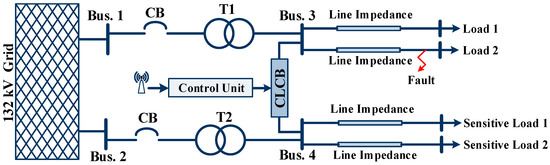
Figure 1.
Single line diagram of the distribution network.
Bus 3 is assumed to be faulty and bus 4 is connected to the sensitive loads by feeders. The CLCB topology is shown in Figure 2.
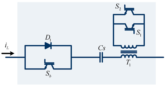
Figure 2.
Current limiting circuit breaker topology.
In this circuit, D1 and Sb are power electronics diode and IGBT switch, respectively, and Cs is a series capacitor bank. In addition, the primary side of transformer T1 is connected in series to a line and its secondary is connected to two anti-parallel IGBTs. During normal operation mode, the resonance transformer and series capacitor form a series resonance L-C tank with resonance frequency equal to electrical network frequency. In this case, D1 for positive half-cycles and Sb for negative half-cycles, are in on-state and voltage drop on the CLCB components is negligible. The CLCB configuration during normal operation mode is shown in Figure 3a.
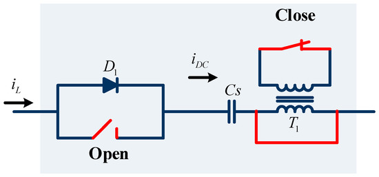
Figure 3.
Proposed CLCB topology (a) normal operation, (b) fault current limiting, and (c) fault current breaking.
During a fault, the fault current increases and passes the threshold current level (IL). In this case, the control circuit detects the fault and turns on the antiparallel IGBTs. Therefore, the secondary side of the resonance transformer is short-circuited and the resonance transformer shows negligible impedance. The series capacitor impedance then limits the fault current. Figure 3b shows the CLCB topology in the fault current limiting mode. To open the faulty line, the control circuit turns off Sb after one cycle delay. In this case, D1 passes a positive half-cycle and the induced DC voltage on the series capacitor charges it. Then, the series capacitor opens the faulty line successfully. The CLCB topology in circuit breaker mode is shown in Figure 3c.
3. Analytical Studies
3.1. CLCB Operation in Normal Mode
In this mode, the secondary side of the transformer is open and the series resonance LC tank is in resonance condition. Therefore, the electrical network equivalent circuit in steady state condition is an R-L circuit where R and L equal to source, line, and load resistances and inductances, respectively. In addition, the source voltage is denoted with Vs(t) and is equal to Vm sin(ωt). By applying Kirchhoff law to the network, the line current for the steady-state condition,
then
Equation (2) shows the sinusoidal nature of the line current during the normal operation mode.
3.2. CLCB Operation in Fault Current Limiting Mode
During a fault, the resonance transformer is by-passed via IGBTs and the equivalent circuit of the network is an R-L-C circuit, where R and L include the source, line, and CLCB (transformer leakage and magnetization) resistances and inductances, respectively, and C is the series capacitor bank. In this case, the RLC circuit current can be obtained using the Equation (3)
where initial conditions for L is , for C is , and VD and VIGBT is IGBT voltage drop, respectively
Solving this equation results in the following equation:
where , , , and the value of A1 and A2 can be obtained using initial conditions. Then,
The obtained value for iL(t) includes two-term responses and one steady-state term. The transient responses are dampened after some milliseconds. The steady-state response includes the phase angle shift as shown in the simulation results.
3.3. CLCB Operation in Circuit Breaking Mode
In this case, the electrical network is in faulty condition and the suggested CLCB should open the faulty line. Therefore, the control system turns off Sb and induces the DC voltage on the series capacitor. The charged capacitor then opens the faulty line and the transmission line current reaches zero. In this case, we have:
The Equation (7) includes two exponential parts and, the line current reaches zero.
4. Control Strategy
The control block diagram of the proposed CLCB is shown in Figure 4. In the normal mode, the Sb was in on-state for negative half-cycles and IGBTs were in off-state. Therefore, the line current (iL) passed through the series resonance LC tank and the CLCB showed negligible impedance.
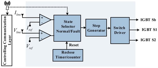
Figure 4.
Bock diagram presentation of CLCB control logic.
At fault inception, the IL becomes greater than the maximum permissible current (Iref) and the control circuit turns on the anti-parallel IGBTs and turns off the Sb after the one cycle delay. Therefore, the resonance transformer is bypassed and the impedance of the series capacitor limits the fault current. By turning off the Ts1, the faulty line is opened and the CLCB acts as a circuit breaker. After fault removal, the step generator resets the gates pulses of the power electronics switches and returns the network to the pre-fault condition.
5. Simulation Results
The single line diagram of the electrical network including CLCB and shown in Figure 1 is simulated. The parameters of the suggested CLCB and electrical network are listed in Table 1. The results are obtained considering a single-phase to the ground short-circuit fault at bus A. The simulation results are studied for the system with and without using the CLCB.

Table 1.
Parameters of electrical network and CLCB.
In normal operation mode, both buses delivered power to the loads at half capacity (12.5 MVA). In this case, there was no voltage drop on the CLCB devices and because of the system symmetry; no current was circulated through the interconnected CLCB. In addition, it is assumed that there was no CLCB connected to the feeder and line current was in normal condition as shown in Figure 5. A fault at bus (A) could cause severe voltage sag, which would affect the sensitive load. In this case, the fault current increased and its amplitude reached 6.8 kA as shown in Figure 5.
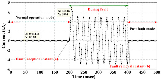
Figure 5.
Fault current at bus A without using CLCB.
It is assumed that the fault occurred at bus (A) which produced an increase of current in the interconnection CLCB and bus (A) experienced a transient voltage. To prevent the service interruption at a sensitive load, the CLCB was connected in series with the feeder and interconnection bus as shown in Figure 1. In fault case, the CLCB impedance increased and its series LC tank was in series with the interconnection bus during the increase of the current. Therefore, its impedance decreased the faulty line current to an acceptable level and compensated the voltage sag at bus (A). Figure 6 and Figure 7 show the fault current and bus (A) voltage for both cases with and without using CLCB.
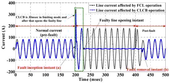
Figure 6.
Fault current during the normal operation and fault with connected CLCB.
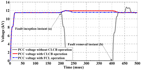
Figure 7.
RMS value of bus A voltage with and without using CLCB.
In the case 1 (without CLCB), the fault current increased to the peak value of 6.8 kA but by using the CLCB, the fault current was limited to the peak value of 200 A. It is shown that in case 1, the voltage of the bus (A) decreased approximately to zero. However, CLCB not only reduced the voltage sag to 0.9 pu, but also it opened the faulty line and fixed the bus (A) voltage to 1 pu. During the normal operation mode, the impedance of the series resonance LC tank was close to zero and there was no voltage drop on it. During the fault, the resonance transformer was bypassed and a considerable voltage drop was seen on the series capacitor. In circuit breaking mode, the induced DC voltage on the series capacitor charged it higher than the peak voltage of the network and caused it to open the faulty line. Figure 8 shows the series capacitor voltage during normal operation and fault for AC and DC operation cases.
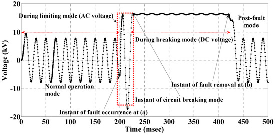
Figure 8.
Series capacitor voltage during the normal operation and fault including fault current limiting mode (AC operation) and circuit breaking mode (DC capacitor charging).
As shown in Figure 8, after fault inception, the fault current increased but the impedance of the series capacitor in AC mode decreased the fault current. After one cycle delay, the controller turned off Ts1 and induced DC voltage on the series capacitor charged it with DC voltage. In this case, the faulty line was opened via a series capacitor and the fault current reached zero.
The load voltage during normal and fault operation modes is shown in Figure 9. The fault occurred at instant (a) and the voltage of the load decreased to zero. At instant (b), the fault was cleared and the load voltage returned to the pre-fault value.
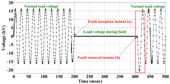
Figure 9.
Load voltage during the normal and fault operation modes.
After the fault removal, the voltage of the electrical load was distorted for a first half-cycle. The stored energy on the series capacitor during the fault period caused this voltage fluctuation.
The CLCB operation and its effect on faulty line current are shown in Figure 10. These comparative plots show the CLCB influence on both decreasing the fault current and opening the faulty line. The dotted plot shows the fault current when there is no connected FCL in series with the feeder. By FCL utilization, the fault current was decreased as shown with dash line in Figure 10.
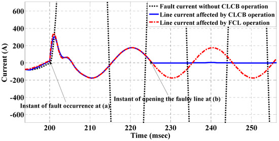
Figure 10.
Comparison of line current during the normal and fault operation modes; with and without using CLCB.
In the instant of fault inception, the first peak of the fault current decreased and after that the limited fault current reached an acceptable level. The blue solid plot shows the line current during normal and fault operation modes affected by the proposed CLCB. At the first cycle of the line fault current, the proposed CLCB acted as a fault current limiter. Then it opened up the faulty line, and current decayed to zero.
6. Experimental Results
To verify the simulation results, a CLCB prototype was built as shown in Figure 11. The CLCB prototype was tested in normal and fault operation modes. Table 2 lists the experimental setup parameters.
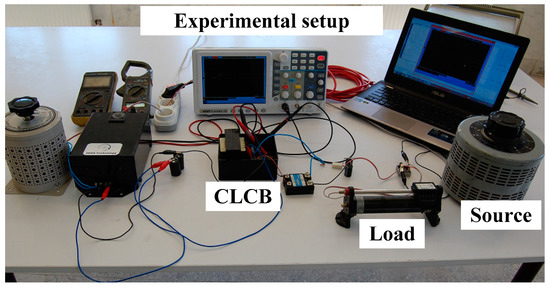
Figure 11.
Prototype of the proposed CLCB.
Table 2.
Experimental setup characteristics.
Using a mechanical switch, a single line to ground fault was implemented. The controlling circuit included a voltage transformer, a current transducer (LTS 25-NP), IGBT gate drivers (TLP250), RC filter, and an Atmel XMEGA microcontroller. Measurements of line voltage and current in faulty condition were processed and detected by microcontroller and operation command was generated in two stages. In the first stage, by operating a switch of the transformer, secondary fault current magnitude was limited. In the second stage, by operating series IGBT, fault current was broken.
Figure 12 shows the line current during the normal and fault operation modes. In this plot, the phase to ground fault occurred at instant (a) via a mechanical switch and was cleared up at instant (b) by the opening of the mechanical switch. As shown here, after the fault occurrence, the CLCB limited the fault current, opened the faulty line, and decreased the fault current to zero. After fault clearance, CLCB recovered the faulty line in less than 20 ms. This measured curve is in fair agreement with Figure 6.
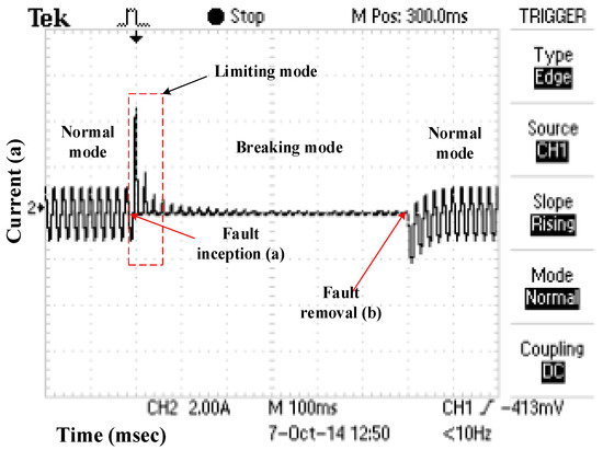
Figure 12.
Line current during the normal and fault operation modes.
Figure 13 shows the protected bus voltage during the normal and fault operation modes. As shown in this figure, CLCB can successfully fix protected bus voltage to an acceptable level during the fault. This figure is in agreement with Figure 7. In this figure, the duration of the normal, fault operation modes, and its effect on the line current can be seen in the upper curve.
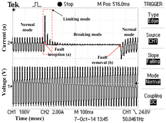
Figure 13.
Protected bus voltage during the normal and fault operation modes.
The voltage of the series capacitor is shown in Figure 14. The series capacitor voltage during the normal operation mode was sinusoidal and this capacitor was in resonance with the series transformer primary. After the fault, by operating series IGBT operation, voltage changed to the DC voltage, which opened the faulty line. This figure is in agreement with Figure 8.
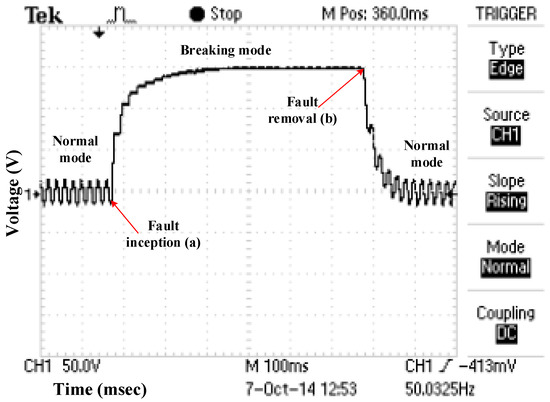
Figure 14.
The voltage of series capacitor during the normal and fault operation modes.
Comparing the proposed CLCB with traditional CB and power electronic based CB, superiority of the proposed structure can be listed as follows:
- A low number of series power electronic switches (two switches);
- Series switch low voltage stress;
- Low current magnitude in breaking state;
- Combination of fault current limiting structure with solid-state breaker;
- Very fast operation in comparison with mechanical breakers.
7. Conclusions
In this paper, a new type of CLCB is proposed. This device acts by dual-function protection, not only limiting the fault current but also open the faulty line similar to a circuit breaker. In practice, its fast response to faults can successfully limit the first peak of the fault current. In addition, the proposed CLCB assists to recover the protected buses voltage to an acceptable level. Therefore, the sensitive loads do not experience a significant voltage sag. The CLCB can be placed as a solid-state circuit breaker (instead of the traditional circuit breakers) and behaves as a fault current limiter. Performance of proposed CLCB is proved by simulation and experimental test results.
Author Contributions
All authors contributed equally to this work and all authors have read and approved the final manuscript.
Funding
This research received no external funding.
Conflicts of Interest
The authors declare no conflict of interest.
References
- Elmitwally, A. Proposed hybrid superconducting fault current limiter for distribution systems. Int. J. Electr. Power Energy Syst. 2009, 31, 619–625. [Google Scholar] [CrossRef]
- Didier, G.; Lévêque, J. Influence of fault type on the optimal location of superconducting fault current limiter in electrical power grid. Int. J. Electr. Power Energy Syst. 2014, 56, 279–285. [Google Scholar] [CrossRef]
- Prigmore, J.R.; Mendoza, J.A.; Karady, G.G. Comparison of four different types of ferromagnetic materials for fault current limiter applications. IEEE Trans. Power Deliv. 2013, 28, 1491–1498. [Google Scholar] [CrossRef]
- Chen, S.; Yang, P.; Xu, W.; Bian, X.; Wang, W. Side effects of Current-Limiting Reactors on power system. Int. J. Electr. Power Energy Syst. 2013, 45, 340–345. [Google Scholar] [CrossRef]
- Tian, M.; Li, Q.; Li, Q. A controllable reactor of transformer type. IEEE Trans. Power Deliv. 2004, 19, 1718–1726. [Google Scholar] [CrossRef]
- Didier, G.; Leveque, J.; Rezzoug, A. A novel approach to determine the optimal location of SFCL in electric power grid to improve power system stability. IEEE Trans. Power Deliv. 2013, 28, 978–984. [Google Scholar] [CrossRef]
- Aracil, J.C.; Lopez-Roldan, J.; Coetzee, J.C.; Darmann, F.; Tang, T. Analysis of electromagnetic forces in high voltage superconducting fault current limiters with saturated core. Int. J. Electr. Power Energy Syst. 2012, 43, 1087–1093. [Google Scholar] [CrossRef]
- Rouzbehi, K.; Candela, J.I.; Luna, A.; Gharehpetian, G.B.; Rodriguez, P. Flexible Control of Power Flow in Multiterminal DC Grids Using DC–DC Converter. IEEE J. Emerg. Sel. Top. Power Electron. 2016, 4, 1135–1144. [Google Scholar] [CrossRef]
- Heidary, A.; Radmanesh, H.; Fathi, S.H.; Gharehpetian, G.B. Series transformer based diode-bridge-type solid state fault current limiter. Front. Inf. Technol. Electron. Eng. 2015, 16, 769–784. [Google Scholar] [CrossRef]
- Ghanbari, T.; Farjah, E. Development of an efficient solid-state fault current limiter for microgrid. IEEE Trans. Power Deliv. 2012, 27, 1829–1834. [Google Scholar] [CrossRef]
- Fereidouni, A.R.; Vahidi, B.; Mehr, T.H. The impact of solid state fault current limiter on power network with wind-turbine power generation. IEEE Trans. Smart Grid 2013, 4, 188–1196. [Google Scholar] [CrossRef]
- Heidary, M.A.; Radmanesh, H.; Rouzbehi, K.; Pou, J. A dc-reactor based solid-state fault current limiter for hvdc applications. IEEE Trans. Power Deliv. 2019, 34, 720–728. [Google Scholar] [CrossRef]
- Javadi, H.; Ali Mousavi, S.M.; Khederzadeh, M. A novel approach to increase FCL application in preservation of over-current relays coordination in presence of asynchronous DGs. Int. J. Electr. Power Energy Syst. 2013, 44, 810–815. [Google Scholar] [CrossRef]
- Naderi, S.B.; Jafari, M.; Hagh, M.T. Controllable resistive type fault current limiter (CR-FCL) with frequency and pulse duty-cycle. Int. J. Electr. Power Energy Syst. 2014, 61, 11–19. [Google Scholar] [CrossRef]
- Rouzbehi, K.; Miranian, A.; Candela, J.; Luna, A.; Rodriguez, P. Intelligent voltage control in a dc micro-grid containing PV generation and energy storage. In Proceedings of the 2014 IEEE PES T&D Conference and Exposition, Chicago, IL, USA, 14–17 April 2014; pp. 1–5. [Google Scholar]
- Rouzbehi, K.; Miranian, A.; Luna, A.; Rodriguez, P. Towards fully controllable multi-terminal DC grids using flexible DC transmission systems. In Proceedings of the 2014 IEEE Energy Conversion Congress and Exposition (ECCE), Pittsburgh, PA, USA, 14–18 September 2014; pp. 5312–5316. [Google Scholar]
- Kang, B.; Park, J.-D. Application of thyristor-controlled series reactor for fault current limitation and power system stability enhancement. Int. J. Electr. Power Energy Syst. 2014, 63, 236–245. [Google Scholar] [CrossRef]
- Lanes, M.; Matusalem, B.; Barbosa, P.G. Fault current limiter based on resonant circuit controlled by power semiconductor devices. IEEE Lat. Am. Trans. 2007, 5, 311–320. [Google Scholar] [CrossRef]
- Radmanesh, H.; Heidary, A.; Fathi, S.H.; Gharehpetian, G.B. Dual function ferroresonance and fault current limiter based on DC reactor. IET Gener. Trans. Distrib. 2016, 10, 2058–2065. [Google Scholar] [CrossRef]
- Heidary, A.; Radmanesh, H.; Fathi, S.H.; Khamse, H.R.R. Improving transient recovery voltage of circuit breaker using fault current limiter. Res. J. Appl. Sci. Eng. Technol. 2012, 4, 5123–5128. [Google Scholar]
- Javadi, H. Fault current limiter using series impedance combined with bus sectionalizing circuit limiter. Int. J. Electr. Power Energy Syst. 2011, 33, 731–736. [Google Scholar] [CrossRef]
- Hoshino, T.; Itsuya, M.; Nakamura, T.; Salim, K.M.; Yamada, M. Non-inductive variable reactor design and computer simulation of rectifier type superconducting fault current limiter. IEEE Trans. Appl. Supercond. 2005, 15, 2063–2066. [Google Scholar] [CrossRef]
- Radmanesh, H.; Fathi, S.H.; Gharehpetian, G.B.; Heidary, A. A novel solid-state fault current-limiting circuit breaker for medium-voltage network applications. IEEE Trans. Power Deliv. 2016, 31, 236–244. [Google Scholar] [CrossRef]
- Sano, K.; Takasaki, M. A surge-less solid-state DC circuit breaker for voltage source converter based HVDC systems. IEEE Trans. Ind. Appl. 2014, 50, 2690–2699. [Google Scholar] [CrossRef]
- Zou, J.; Chen, J.; Dong, E. Study of fast-closing switch based fault current limiter with series compensation. Int. J. Electr. Power Energy Syst. 2002, 24, 719–722. [Google Scholar] [CrossRef]
- Gregory, G.; Lippert, K.J. Applying low-voltage circuit breakers to limit arc-flash energy. IEEE Trans. Ind. Appl. 2012, 48, 1225–1229. [Google Scholar] [CrossRef]
- Meyer, C.; De Doncker, R.W. Solid-state circuit breaker based on active thyristor topologies. IEEE Trans. Power Electron. 2006, 21, 450–458. [Google Scholar] [CrossRef]
- Gharibpour, H.; Monsef, H.; Ghanaatian, M. The comparison of two control methods of power swing reduction in power system with UPFC compensator. In Proceedings of the 20th Iranian Conference on Electrical Engineering (ICEE2012), Tehran, Iran, 15–17 May 2012; pp. 386–391. [Google Scholar]
- Sharma, J.P.; Chauhan, V. Analysis and control of fault current by firing angle control of solid state fault current limiter. In Proceedings of the 2015 International Conference on Energy Systems and Applications, Pune, India, 30 October 2015; pp. 527–530. [Google Scholar]
© 2019 by the authors. Licensee MDPI, Basel, Switzerland. This article is an open access article distributed under the terms and conditions of the Creative Commons Attribution (CC BY) license (http://creativecommons.org/licenses/by/4.0/).