Abstract
This paper introduces a new chaotic system with two circles of equilibrium points. The dynamical properties of the proposed dynamical system are investigated through evaluating Lyapunov exponents, bifurcation diagram and multistability. The qualitative study shows that the new system exhibits coexisting periodic and chaotic attractors for different values of parameters. The new chaotic system is implemented in both analog and digital electronics. In the former case, we introduce the analog circuit of the proposed chaotic system with two circles of equilibrium points using amplifiers, which is simulated in MultiSIM software, version 13.0 and the results of which are in good agreement with the numerical simulations using MATLAB. In addition, we perform the digital implementation of the new chaotic system using field-programmable gate arrays (FPGA), the experimental observations of the attractors of which confirm its suitability to generate chaotic behavior.
1. Introduction
A nonlinear, aperiodic and continuous-time dynamical system is said to be chaotic if it exhibits sensitive dependence on initial conditions [1]. Thus, an autonomous continuous-time system with dimension is chaotic if there is a positive element in its Lyapunov exponents spectrum. A 3D dissipative autonomous chaotic system is characterized by the existence of positive, zero and negative Lyapunov exponents with a negative sum of the Lyapunov exponents [2]. Dissipative systems have a state space volume that contracts on average along the trajectory so that the orbit approaches an attractor of measure zero in the state space. If the dissipative system is chaotic, the attractor is strange with a non-integer dimension and fractal structure [2].
Recently, chaotic systems with a closed curve of equilibrium points have attracted much attention in the chaos literature. Gotthans and Petrzela proposed a chaotic system with circular equilibrium by using search irregular behavior of nonlinear models [3]. Pham et al. proposed a new chaotic system with different shapes of equilibria such as ellipse equilibrium, square-shaped equilibrium and rectangle-shaped equilibrium [4]. Pham et al. constructed a novel chaotic system with heart-shaped curve equilibrium curve, which can exhibit hidden attractors [5]. Pham et al. proposed a new chaotic system with equilibria located on the rounded square loop and discussed its circuit implementation [6]. In addition, Mobayen et al., presented a new chaotic system with a three-leaved clover equilibrium and its application in image encryption [7]. Sambas et al. proposed a new chaotic system with pear-shaped equilibrium and discussed its electronic circuit simulation [8]. Vaidyanathan et al. proposed a new chaotic system with axe-shaped equilibrium and discussed its control applications [9]. Vaidyanathan et al. proposed a new chaotic system with a cloud-shaped curve of equilibrium and discussed its application to sound encryption [10]. Mobayen et al. announced a new chaotic system with a boomerang-shaped equilibrium and discussed its application to sound encryption [11]. Some recent 3D chaotic systems with a closed curve of equilibrium points [3,4,5,6,7,8,9,10,11] are presented in Table 1.

Table 1.
Chaotic systems with a closed curve of equilibrium points.
In this work, we propose a new chaotic system with two circles of equilibrium points. The closed curve of equilibrium points in this work consists of two circles that intersect at the origin and a chaotic system with such a closed curve is a new contribution in the chaos literature. The phase portraits of the new chaotic system are illustrated using numerical simulations with MATLAB. The qualitative properties of the new chaotic system are analyzed by calculating Lyapunov exponents, bifurcation diagram and multistability. The dynamical analysis shows that the new system exhibits coexisting periodic and chaotic attractors for different values of parameters.
Chaos in electrical circuits is an active research area and many seminal papers have been published on chaotic circuits in the literature [12,13,14,15,16]. Matsumoto observed a chaotic attractor from Chua’s circuit [12]. Chua et al. announced a chaotic circuit with double-scroll attractor and analyzed its properties [13]. Chua and Lin discussed canonical realization of Chua’s circuit family [14]. Chua et al. discussed a universal circuit for studying and generating chaos [15]. Sprott made a detailed study of simple chaotic systems and circuits [16].
Furthermore, the electronic circuit of the proposed chaotic system with two circles of equilibrium points is implemented in MultiSIM software, version 13.0. The oscilloscope results of the electronic circuit design of the new chaotic system are consistent with the numerical MATLAB simulations of the new chaotic system. Finally, we implement the new chaotic system using the field-programmable gate array (FPGA) circuit. FPGA circuit design has several applications in engineering [17].
2. Dynamical Model of the New Chaotic System
A general model of chaotic systems with a curve of equilibrium points has been proposed by Pham et al. [6] as follows:
Motivated by the research work on chaotic systems with closed curves of equilibrium points (see Table 1) and the general System (1), we report a new chaotic system with two circles of equilibrium points given by:
where is the state and a, b, c are positive parameters. System (1) can generate chaos for a = 4, b = 4.5, c = 1 and initial conditions X (0) = (0.01, 0.02, 0.01).
The equilibrium points of the new System (2) are tracked by solving the following system of equations:
Simplifying System (3), we see that the equilibrium points of the System (2) are characterized: by
z = 0 and x2 + y2 -|x| = 0
Equation (4) represents two circles of equilibrium points (x2 + y2 + x= 0 and x2 + y2 −x = 0) touching at the origin in the x-y plane as shown in Figure 1.
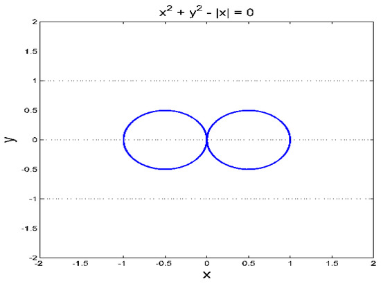
Figure 1.
Two circles of equilibrium points of the new System (2) in the x-y plane.
By fixing (a, b, c) = (4, 4.5, 1) and X(0) = (0.01, 0.02, 0.01), we numerically solve System (2) via the fourth order Runge-Kutta method. MATLAB plots depicting the chaotic attractor of the new System (2) are shown in Figure 2a–c.
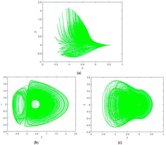
Figure 2.
MATLAB plots of the new chaotic System (2) (a) x-y plane, (b) y-z plane and (c) x-z plane.
The bifurcation analysis of a nonlinear dynamical system is useful for knowing the behavior of the system both chaotic or periodic behavior for certain values of the system parameters [18,19,20,21,22,23]. Lyapunov exponent spectrum and bifurcation diagram are obtained for b = 4.5, c = 1 as a varies between 4 to 15 and initial condition X(0) = (0.01, 0.02, 0.01). Lyapunov exponent spectrum and bifurcation diagram of System (2) are given in Figure 3a,b, respectively. Obviously, from the bifurcation diagram and Lyapunov exponent spectrum, we conclude that System (2) exhibits robust chaos in the whole region. We note that the famous Wolf’s algorithm [24] is used for calculating the Lyapunov exponents.
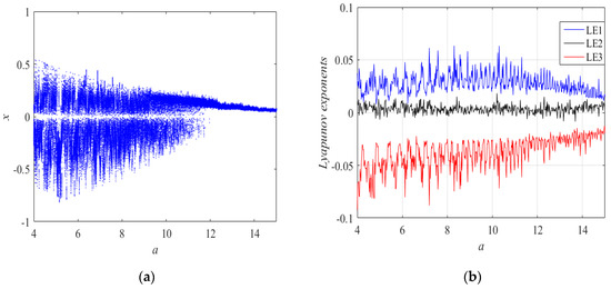
Figure 3.
(a) Bifurcation diagram of System (2) with respect to parameter a and (b) Lyapunov exponent spectrum of the system with respect to parameter a.
3. Multistability Analysis
Multistability is an interesting phenomenon and usually exists in many chaotic systems. As can be seen from the bifurcation diagram in Figure 4, there exist coexisting attractors in the region of [5.3, 10] (see the right side of the black solid line in the Figure 4). When the parameters b = 4.5, c = 1 and vary a in the region of [4,15]. A set of initial states with blue color (0.3, 0.02, 0.01) and another set of initial states with red color (–0.3, 0.02, 0.01) are fixed. Some sample coexisting attractors are presented. For example, when a = 6, the system produces the coexisting periodic attractor and chaotic attractor as shown in Figure 5a,b. Moreover, the coexisting periodic attractors are found in the new System (2) with a = 10 as shown in Figure 5c,d.
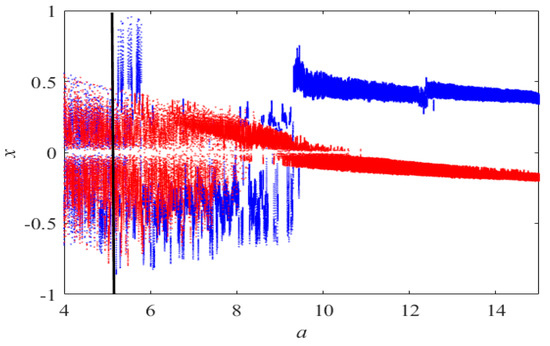
Figure 4.
Coexisting bifurcation diagram of the state variable x with respect to the control parameter a.
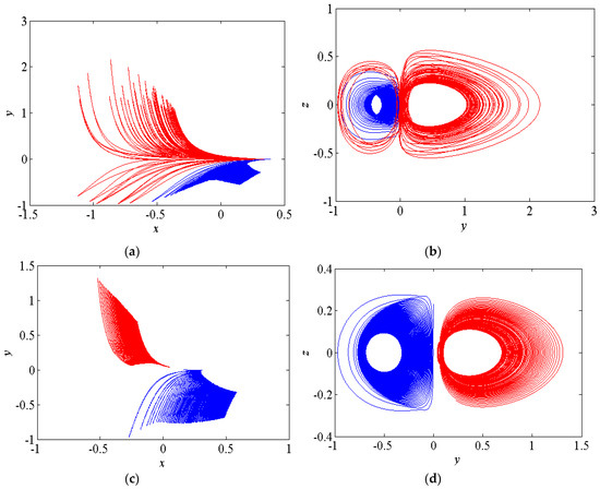
Figure 5.
(a) The coexisting periodic attractor and chaotic attractor in x-y plane (b) The coexisting periodic attractor and chaotic attractor in y-z plane (c) The coexisting periodic attractors in x-y plane and (d) The coexisting periodic attractors in y-z plane.
4. The Electronic Circuit Implementation
The main purpose of electronic implementation using MultiSim version 13.0 is to confirm the suitability of system behavior with numerical simulations. The schematic diagram of new chaotic System (2) is shown in Figure 6. In this section, we set X = 4x, Y = 4y and Z = 4z. We obtain the following dimensionless system:
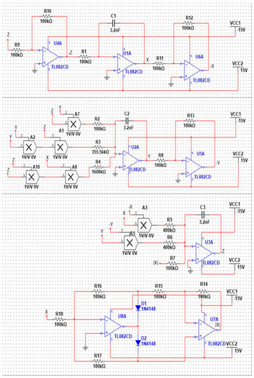
Figure 6.
The circuit schematic diagram of the new chaotic system.
By applying Kirchhoff’s circuit laws, we get its circuital equations:
The values of circuit components have been chosen as: R1 =R5 = R6 = 400 kΩ, R3 = 355.56 kΩ, R4 = 1600 kΩ, R2 = R7 = R8 = R9 = R10 = R11 = R12 = R13 = R14 = R15 = R16 = R17 = R18 = 100 kΩ and C1 = C2 = C3 = 3.2 nF. The phase portraits of the circuit are represented in Figure 7a–c. A very good similarity between MATLAB simulation results (shown in Figure 2a–c) and MultiSim version 13.0 simulation results (shown in Figure 7a–c) can be observed. Figure 8 shows spectral distribution for chaotic signals in the three coordinates: X, Y and Z. The power spectra of the produced signals are broadband, typical of chaotic signals. They span to a frequency range that goes beyond 5 kHz. The peak of the frequency spectrum was measured to be at 0.4 kHz and it corresponds to a prevailing frequency of the implementing oscillating loop. The frequency is quite low. Thus, the new chaotic system can only be used for low frequency applications.
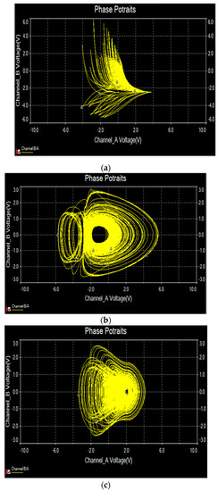
Figure 7.
Phase portraits of the new chaotic system in Multisim (a) X-Y plane, (b) Y-Z plane and (c) X-Z plane.
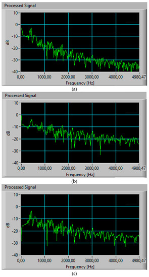
Figure 8.
The spectral distribution of the new chaotic system: (a) X-signal, (b) Y-signal and (c) Z-signal.
5. FPGA Realization
The digital implementation of chaotic systems using field-programmable gate arrays (FPGA) has advantages, such as verification and fast prototyping, exploitation of the processing speed, high computational power and programming flexibility. Implementing chaotic systems like this new one described by System (2) using FPGAs, requires choosing the appropriate numerical method to discretize the equations and then describe the building blocks for synthesis purposes. The FPGA-based implementation is then suitable to develop several applications in data encryption and secure communications, as shown in [25].
Applying one-step methods to solve System (1) is quite enough to perform the FPGA-based implementation. In this manner, the mathematical model described in System (1) is discretized applying Forward-Euler and the fourth-order Runge-Kutta methods. Forward-Euler leads us to the discretized equations given in System (2).
Figure 9 shows the block description of the chaotic system and by applying the Forward Euler method. Applying the fourth-order Runge-Kutta method leads us to much bigger equations, which require more digital blocks for its implementation in the FPGA, but this method provides higher precision than Forward Euler. The choose of the step-size is also different in each numerical method. For instance, however in this work we set it to h = 0.001 for both numerical methods. The digital implementation can be done using computer arithmetic of 32 bits, with a fixed-point notation in the format 7.25, which means that one bit is associated to the sign, six bits to the integer part and 25 bits to the fractional part of a number. From System (7), one can identify the use of adders, subtractors, multipliers and a special block to implement the absolute value of the state variable |x|. The multipliers with two state variables as inputs are taken from the FPGA resources and the multipliers having one number as input (a, b, c, h), are designed as single-constant multiplier (SCM) blocks, which reduce the use of digital resources. To increase the processing speed, all blocks include a clock (clk) pin, as shown in Figure 9, in which one can change the numerical method labeled as Integrator Forward Euler. Details on FPGA design issues can be found in [26].
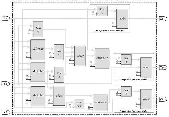
Figure 9.
Block description of the new chaotic system given in System (1), discretized with Forward-Euler.
Table 2 shows the hardware resources used to implement the new chaotic system given in System (2) and using the FPGA Cyclone IV EP4CGX150DF31C7. The VHDL descriptions were performed using the synthesizer of software \Quartus II 13.0. The last two rows represent the number of clock cycles to obtain a new iteration from the initial iteration values Xn, Yn, Zn to the next values Xn+1, Yn+1, Zn+1 shown in Figure 8. The data at each iteration requires a latency in nanoseconds and they are calculated using a 50 MHz clock signal.
Table 2.
Resources using the FPGA Cyclone IV EP4CGX150DF31C7 for implementing System (2) applying Forward-Euler and fourth-order Runge-Kutta methods.
Figure 10, Figure 11 and Figure 12 show the 2D views of the new chaotic attractors associated to the FPGA-based implementation of System (2) and using the FPGA Cyclone IV EP4CGX150DF31C7. The experimental chaotic time series of each state variable were truncated to observe the data on the oscilloscope when using a 16-bits digital to analog (DAC) converter of 1 megasample/second. From these chaotic attractors one can conclude on the good agreement between the simulated and experimental results for the new chaotic oscillator with two circles of equilibrium points.
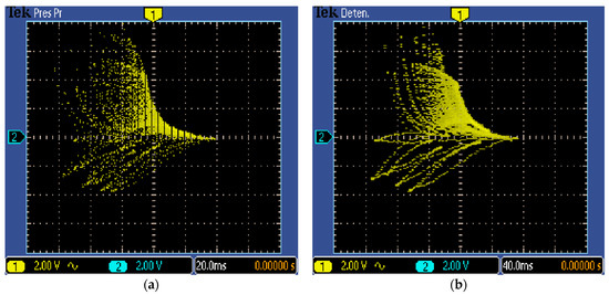
Figure 10.
Oscilloscope views in the x-y plane (2v/div) of the new chaotic System (2) implemented in field-programmable gate array (FPGA) and with: (a) Forward-Euler with h = 0.001 and (b) fourth-order Runge-Kutta with h = 0.01.
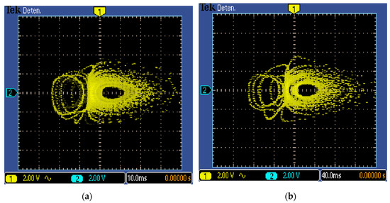
Figure 11.
Oscilloscope views in the y-z plane (2v/div) of the new chaotic System (2) implemented in FPGA and with: (a) Forward-Euler with h = 0.001 and (b) fourth-order Runge-Kutta with h = 0.01.
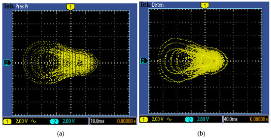
Figure 12.
Oscilloscope views in the x-z plane (2v/div) of the new chaotic System (2) implemented in FPGA and with: (a) Forward-Euler with h = 0.001 and (b) fourth-order Runge-Kutta with h = 0.01.
6. Conclusions
This paper introduced a new chaotic system with two circles of equilibrium points, which is a new contribution to the literature of chaotic systems with closed curves of equilibrium points. Lyapunov exponents, bifurcation diagrams and coexisting attractors have been used to investigate the complex behaviors of the system. We showed that the chaotic system exhibits multistability with coexisting attractors. For practical implementation, an electronic circuit of the new chaotic system has been designed using both MultiSIM version 13.0 and FPGA. MultiSIM based simulation results of System (1) are in good agreement with the FPGA realization. Chaotic systems with realizations in circuits and FPGA have good engineering applications such as pseudo-random number generator (PRNG), encryption, steganography, secure communication devices, etc.
Author Contributions
Conceptualization, A.S. and S.; methodology, S.V. and S.Z.; software, E.T.-C., S.Z. and Y.H.; validation, A.S., O.G.-F. and G.G.; formal analysis, S.V., E.T.-C.; writing—original draft, A.S., S.V. and S.
Funding
This research was funded Ministry of Research and Higher Education, Republik of Indonesia through Penelitian Kerja Sama Antar Perguruan Tinggi (Grant No. 2891/L4/PP/2019).
Acknowledgments
Aceng Sambas thanks to KEMENRISTEKDIKTI for the financial support to through Project No. 2891/L4/PP/2019 (Penelitian Kerja Sama Antar Perguruan Tinggi).
Conflicts of Interest
The authors declare no conflict of interest.
References
- Strogatz, S.H. Nonlinear Dynamics and Chaos: With Applications to Physics, Biology, Chemistry and Engineering; Westview Press: Boulder, CO, USA, 2015. [Google Scholar]
- Vaidyanathan, S.; Volos, C. Advances and Applications in Chaotic Systems; Springer: Basel, Switzerland, 2016. [Google Scholar]
- Gotthans, T.; Petrzela, J. New class of chaotic systems with circular equilibrium. Nonlinear Dyn. 2015, 73, 429. [Google Scholar] [CrossRef]
- Pham, V.T.; Jafari, S.; Wang, X.; Ma, J. A chaotic system with different shapes of equilibria. Int. J. Bifurc. Chaos 2016, 26, 1650069. [Google Scholar] [CrossRef]
- Pham, V.T.; Jafari, S.; Volos, C. A novel chaotic system with heart-shaped equilibrium and its circuital implementation. Optik 2017, 131, 343–349. [Google Scholar] [CrossRef]
- Pham, V.T.; Jafari, S.; Volos, C.; Giakoumis, A.; Vaidyanathan, S.; Kapitaniak, T. A chaotic system with equilibria located on the rounded square loop and its circuit implementation. IEEE Trans. Circuits Syst. II Express Briefs 2016, 63, 878–882. [Google Scholar] [CrossRef]
- Mobayen, S.; Volos, C.; Kaçar, S.; Çavuşoğlu, Ü. New class of chaotic systems with equilibrium points like a three-leaved clover. Nonlinear Dyn. 2018, 91, 939–956. [Google Scholar] [CrossRef]
- Sambas, A.; Vaidyanathan, S.; Mamat, M.; Mohamed, M.A. A new chaotic system with a pear-shaped equilibrium and its circuit simulation. Int. J. Electr. Comput. Eng. 2018, 8, 4951. [Google Scholar] [CrossRef]
- Vaidyanathan, S.; Sambas, A.; Mamat, M. A new chaotic system with axe-shaped equilibrium, its circuit implementation and adaptive synchronization. Arch. Control Sci. 2018, 28, 443. [Google Scholar]
- Vaidyanathan, S.; Sambas, A.; Kaçar, S.; Çavuşoğlu, Ü. A new three-dimensional chaotic system with a cloud-shaped curve of equilibrium points, its circuit implementation and sound encryption. Int. J. Model. Identif. Control 2018, 30, 184. [Google Scholar] [CrossRef]
- Mobayen, S.; Vaidyanathan, S.; Sambas, A.; Kaçar, S.; Çavuşoğlu, Ü. A novel chaotic system with boomerang-shaped equilibrium, its circuit implementation and application to sound encryption. Iran. J. Sci. Technol. Trans. Electr. Eng. 2019, 43, 1–12. [Google Scholar] [CrossRef]
- Matsumoto, T. A chaotic attractor from Chua’s circuit. IEEE Trans. Circuits Syst. 1984, 31, 1055. [Google Scholar] [CrossRef]
- Chua, L.O.; Komuro, M.; Matsumoto, T. The double-scroll family. IEEE Trans. Circuits Syst. 1986, 33, 1073. [Google Scholar] [CrossRef]
- Chua, L.O.; Lin, G.N. Canonical realization of Chua’s circuit family. IEEE Trans. Circuits Syst. 1990, 37, 885. [Google Scholar] [CrossRef]
- Chua, L.O.; Wu, C.W.; Huang, A. A universal circuit for studying and generating chaos—Part I. Routes to chaos. IEEE Trans. Circuits Syst. 1993, 40, 732. [Google Scholar] [CrossRef]
- Sprott, J.C. Simple chaotic systems and circuits. Am. J. Phys. 2000, 68, 758. [Google Scholar] [CrossRef]
- Kim, H.; Kim, Y.; Ji, H.; Park, H.; An, J.; Song, H.; Kim, Y.T.; Lee, H.; Kim, K. A single-chip FPGA holographic video processor. IEEE Trans. Ind. Electron. 2019, 66, 2066. [Google Scholar] [CrossRef]
- Sambas, A.; Vaidyanathan, S.; Zhang, S.; Zeng, Y.; Mohamed, M.A.; Mamat, M. A new double-wing chaotic system with coexisting attractors and line equilibrium: Bifurcation analysis and electronic circuit simulation. IEEE Access 2019, 7, 115454–115462. [Google Scholar] [CrossRef]
- Li, C.; Hu, W.; Sprott, J.C.; Wang, X. Multistability in symmetric chaotic systems. Eur. Phys. J. Spec. Top. 2015, 224, 1493–1506. [Google Scholar] [CrossRef]
- Li, C.; Sprott, J.C. Coexisting hidden attractors in a 4-D simplified Lorenz system. Int. J. Bifurc. Chaos 2014, 24, 1450034. [Google Scholar] [CrossRef]
- Zhang, S.; Zeng, Y.; Li, Z.; Wang, M.; Xiong, L. Generating one to four-wing hidden attractors in a novel 4D no-equilibrium chaotic system with extreme multistability. Chaos Interdiscip. J. Nonlinear Sci. 2018, 28, 013113. [Google Scholar] [CrossRef]
- Zhang, S.; Zeng, Y.; Li, Z. One to four-wing chaotic attractors coined from a novel 3D fractional-order chaotic system with complex dynamics. Chin. J. Phys. 2018, 56, 793–806. [Google Scholar] [CrossRef]
- Sun, K.; Wang, X.; Sprott, J.C. Bifurcations and chaos in fractional-order simplified Lorenz system. Int. J. Bifurc. Chaos 2010, 20, 1209–1219. [Google Scholar] [CrossRef]
- Wolf, A.; Swift, J.B.; Swinney, H.L.; Vastano, J.A. Determining Lyapunov exponents from a time series. Physica D 1985, 16, 285–317. [Google Scholar] [CrossRef]
- Fernandez, O.G.; Cano, A.M.; Cuautle, E.T.; Perez, J.C.N.; Magdaleno, J.J.R. On the synchronization techniques of chaotic oscillators and their FPGA-based implementation for secure image transmission. PLoS ONE 2019, 14, e0209618. [Google Scholar]
- Cuautle, E.T.; Fraga, L.G.; Magdaleno, J.R. Engineering Applications of FPGAs; Springer: Basel, Switzerland, 2016. [Google Scholar]
© 2019 by the authors. Licensee MDPI, Basel, Switzerland. This article is an open access article distributed under the terms and conditions of the Creative Commons Attribution (CC BY) license (http://creativecommons.org/licenses/by/4.0/).