Abstract
A mechanically reconfigurable phased array antenna (MRPA) with switchable radiation and scattering characteristics is presented. By adjusting the height of each array element, a continuous aperture phase response is achieved, enabling mechanical beam steering without electronic phase shifters. In the radiation mode, a height-induced phase gradient is used to steer the beam, while in the scattering mode, the same height–phase mapping mechanism produces multi-element phase cancellation for radar cross-section (RCS) reduction. An 8 × 8 prototype operating at 7.9 GHz is designed and validated. The array achieves beam steering up to ±45° with a peak realized gain of 21.5 dBi and an aperture efficiency of 87.6%. Moreover, more than 10 dB monostatic RCS reduction is obtained over a wide frequency range from 3 to 38 GHz. The proposed design provides a unified mechanical approach for radiation enhancement and scattering suppression in multifunctional phased arrays.
1. Introduction
Phased array antennas have become a key technology for high-performance radiation control in satellite communications [1,2,3,4], radar sensing [5,6,7,8], and wireless communication systems [9,10,11,12], owing to their ability to achieve beam steering through flexible manipulation of the aperture phase distribution. According to the phase control mechanism, most reconfigurable phased arrays are implemented using electrically reconfigurable approaches [13,14,15,16,17,18,19,20,21], in which the element phase is typically adjusted by PIN diodes [14,15,16,17,18] or varactor diodes [19,20,21]. These approaches offer fast response and flexible control; however, their phase states are generally discrete, which limits continuous beam steering. Moreover, the required bias networks and active components inevitably introduce additional loss, increased system complexity, and reduced reliability.
Compared with electrically reconfigurable approaches, mechanically reconfigurable phased array antennas realize phase modulation by altering the geometric configuration of the antenna, offering advantages such as low loss, continuous phase tunability, and broadband operation. Existing studies have explored different mechanical means to reconfigure the aperture phase, including rotating antenna elements or phase-modulating structures to steer the beam [22,23], laterally translating radiating or feeding structures to synthesize aperture phase gradients [24], and mechanically tuning waveguide feeding networks or phase-shifting modules to control the phase response [25,26]. In addition, element-height adjustment has been investigated as an effective approach to directly introduce free-space propagation path differences for continuous phase modulation [27,28,29]. Compared with other methods, height-adjustable configurations establish a direct and predictable mapping between the geometric displacement of the elements and the radiation phase without relying on complex feeding phase-shifting networks. Building upon prior studies on height-adjustable mechanically reconfigurable arrays, this work adopts element-height tuning as the phase control mechanism for mechanical beam steering.
With the continuous expansion of application scenarios, phased array antennas are required not only to provide large-angle, high-efficiency beam steering, but also to exhibit reduced electromagnetic visibility during non-operating states or specific mission phases [30,31].
In this work, a mechanically reconfigurable phased array antenna (MRPA) with switchable radiation and scattering characteristics is proposed. By precisely adjusting the height of each array element, a continuously controllable phase response is introduced across the aperture. In the radiation mode, a one-to-one mapping between element height and radiation phase enables mechanical beam steering without electronic phase shifters. In the scattering mode, the same height-induced phase mechanism is exploited to construct phase-cancellation conditions across the array, achieving ultra-wideband radar cross-section (RCS) reduction. The proposed design enables coordinated radiation enhancement and scattering suppression within a unified mechanical reconfiguration framework, providing a promising solution for multifunctional and low-detectability phased array antennas.
2. Element Design and Analysis
2.1. Structure of the MRPA
Figure 1a shows the three-dimensional configuration of the proposed MRPA prototype designed for beam steering. The array consists of a grid track, support frames, and stepper motor-integrated single-layer bow-tie patch antenna units. Height reconfiguration of each antenna unit is achieved through the combined operation of the grid track and stepper motor mechanism, as illustrated in Figure 1b,c. Each stepper motor-integrated antenna unit comprises a patch antenna unit, a support frame, a slide block, a screw rod, and a stepper motor. By controlling the rotational direction of the lead screw rod, the slide block is driven to translate vertically, thereby adjusting the height of the patch antenna relative to the reference plane. This motion raises or lowers the support frame connected to the slide block, ultimately positioning the patch antenna unit at the desired height. The detailed geometry of the patch antenna is shown in Figure 1d.
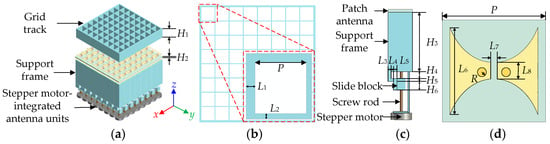
Figure 1.
(a) 3D view of the proposed MRPA, (b) grid track, (c) stepper motor-integrated antenna units, and (d) patch antenna unit (P = 17, H1 = 100, H2 = 5, H3 = 100, H4 = 58, H5 = 3, H6 = 5, L1 = 2.5, L2 = 1.5, L3 = 3, L4 = 3, L5 = 3, L6 = 14, L7 = 0.9, L8 = 1.5, R = 0.635, unit: mm).
Figure 2a shows that the simulated impedance bandwidth (|S11| < −10 dB) of the antenna element is 17.8% (7.22–8.63 GHz) and the simulated radiation pattern of the antenna element is shown in Figure 2b. It exhibits relatively wide radiation patterns and the gain is 5.2 dBi.
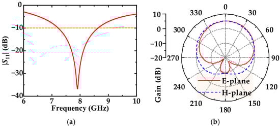
Figure 2.
Simulated (a) reflection coefficients and (b) radiation pattern of the proposed patch antenna unit.
2.2. Working Mechanism of the MRPA
To achieve beam steering of a planar array toward an arbitrary direction (θ0, φ0), the required phase shift for each array element can be expressed as
where k0 is the free-space wavenumber, and (m, n) denote the element indices in the Cartesian coordinate system.
Φ = −k0(msin θ0cos φ0 + nsin θ0sin φ0)
In the proposed MRPA, the required phase shift is realized by introducing a height difference h between array elements. As shown in Figure 3a, a vertical height difference h between array elements introduces an additional propagation path difference, which directly results in a corresponding phase delay. The height-induced phase shift can therefore be approximated as
Φ = −k0h
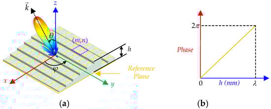
Figure 3.
(a) Coordinate schematic of the mechanically beam steering array antenna, (b) relationship between height and phase shift.
Accordingly, as h varies from 0 to λ0, the phase shift Φ of the antenna element changes between 0 and 2π, as shown in Figure 3b. For steering the beam at an arbitrary angle (θ0, φ0), the height h needed for each element is given by:
h = msin θ0cos φ0 + nsin θ0sin φ0
This equation provides the necessary height variation to achieve the desired phase shift for steering the beam in any specified direction.
2.3. Theory of Multi-Element Phase Cancellation
In the non-radiating mode, the proposed MRPA exploits the height–phase mapping mechanism to suppress backward scattering and achieve low RCS. As shown in Figure 4, when a normally incident plane wave illuminates a surface composed of elements with nonuniform heights, each height level introduces a distinct reflection phase. The resulting phase diversity among the reflected waves leads to destructive interference in the backward direction, thereby reducing the monostatic RCS.
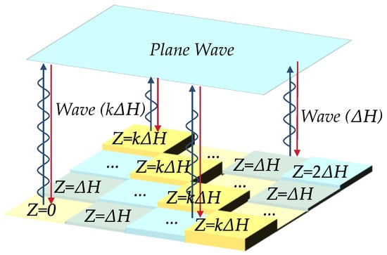
Figure 4.
Schematic of height-induced phase cancellation under normal plane-wave incidence.
For the kth height layer, the reflection phase can be approximated as
where ℎk is the element height relative to the reference plane and k0 = 2π/λ is the free-space wavenumber. By adjusting hk, the reflection phase can be continuously controlled across the full 2π range.
Φk(f) = 2k0hk
As reported in [32], the RCS of such an uneven metal surface depends only on the height-dependent phase distribution and the area proportion of each height level, rather than the absolute spatial arrangement of individual units. Therefore, by reconfiguring the height matrix, the scattering characteristics of the array can be effectively reshaped without altering the physical layout or introducing any lossy or active components.
The normalized monostatic RCS can be expressed as
where αk = Ak/Asum represents the area proportion associated with the kth height level. Once the height distribution is configured to generate appropriate phase diffusion and phase-cancellation conditions, the array exhibits broadband low-RCS performance.
In summary, the proposed design operates in a beam-steering mode by forming a height-induced phase gradient to achieve ±45° mechanical scanning, and switches to a low-scattering mode by reconfiguring the height matrix to satisfy multi-element phase cancellation. This enables a unified radiation–scattering reconfigurable functionality using a purely mechanical control mechanism.
2.4. Parallel Driving Control Circuit for Stepper Motor-Integrated Antenna Units
After obtaining the optimal height matrix using the particle swarm optimization (PSO) algorithm, a corresponding full-wave model is established in CST Studio Suite to validate its effectiveness. Once the desired height configuration is confirmed, the height data are transmitted to the stepper motor-integrated antenna units through a parallel driving control circuit based on an Arduino platform. Figure 5 shows the design of a representative control circuit board that functions as the master control module. It consists of an Arduino Nano microcontroller, four TM74HC595D shift registers, and 24 LB1848M-TRM-E stepper motor driver modules.
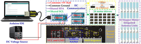
Figure 5.
Parallel driving control circuit for the stepper motor-integrated antenna units.
An I2C (Inter-Integrated Circuit) communication protocol is employed to establish a master–slave control architecture [33]. Upon receiving commands from the host computer, the master controller coordinates the operation of two slave modules via shared serial data (SDA) and serial clock (SCL) lines. The shift registers are used to expand the output channels of the microcontroller, enabling parallel control of multiple motor driver modules. Each motor driver independently controls a stepper motor in a two-phase, four-wire, four-step excitation mode, where each step corresponds to an average vertical displacement of approximately 0.15 mm.
With the proposed parallel driving control circuit, the height of each antenna element can be adjusted independently and accurately, providing sufficient flexibility for implementing both beam-steering and RCS-reconfiguration functions.
3. Results
3.1. Simulated Results of the MRPA
Due to the height variation of the antenna elements, mechanical beam steering may lead to partial blockage of lower elements by higher ones at large scan angles, leading to shadowing effects that affect the radiation characteristics. To evaluate this effect, the radiation performance of the proposed MRPA is compared with that of a conventional planar array for beam directions of θ0 = 30° and θ0 = 45°, as shown in Figure 6.
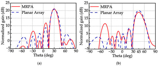
Figure 6.
Simulated patterns of MRPA and planar array at beam direction of (a) θ0 = 30° and (b) θ0 = 45°.
At θ0 = 30°, the realized gains of the proposed MRPA and the planar array are 21.2 dBi and 20.98 dBi, respectively, as shown in Figure 6a. At θ0 = 45°, the realized gain of the MRPA is 19 dBi, compared with 21.5 dBi for the planar array, as illustrated in Figure 6b. In both cases, the proposed MRPA exhibits higher sidelobe levels, which can be attributed to the height-induced perturbation of the aperture field distribution.
As the scan angle increases, the shadowing effect becomes more pronounced, resulting in elevated sidelobe levels. Nevertheless, the proposed MRPA maintains a main-lobe-to-sidelobe isolation exceeding 7 dB, indicating that acceptable radiation performance is preserved even at large scan angles. These results confirm that mechanical height reconfiguration enables effective beam steering with a reasonable trade-off between gain and sidelobe level.
Figure 7a shows the simulated realized gain as a function of scan angle at 7.9 GHz. The realized gain is 21.5 dBi at broadside and decreases to 19 dBi and 18.5 dBi at scan angles of +45° and −45°, respectively, resulting in a gain variation within 3 dB over the ±45° scanning range. This indicates stable radiation performance during beam steering. While Figure 7b presents the variation of realized gain and aperture efficiency with frequency. At 7.9 GHz, an aperture efficiency of 87.6% is achieved. Over the frequency range from 7 to 9 GHz, the realized gain remains above 21 dBi and the aperture efficiency exceeds 60%, demonstrating stable broadband radiation performance.
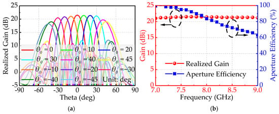
Figure 7.
(a) Realized gain as a function of scan angle from 0° to ±45° at 7.9 GHz, (b) variation of realized gain and aperture efficiency with frequency.
In addition, Figure 8 illustrates the RCS reduction (RCSR) performance of the proposed radiation–scattering reconfigurable array in the scattering mode. The red curve represents the MATLAB (2021)-based theoretical calculation derived from the phase-cancellation model, while the blue curve shows the CST full-wave simulation results. The theoretical results indicate that the backward RCS remains below −10 dB over a wide frequency range from 3 to 40 GHz. In comparison, the simulated −10 dB RCSR bandwidth mainly covers 7.5–40 GHz. The slight discrepancy at lower frequencies is mainly attributed to residual radiation and mutual coupling effects of the antenna elements near the operating band around 7.9 GHz, as well as finite-aperture effects. Overall, good agreement is observed within the effective operating band, validating the proposed mechanically reconfigurable phase-cancellation mechanism.
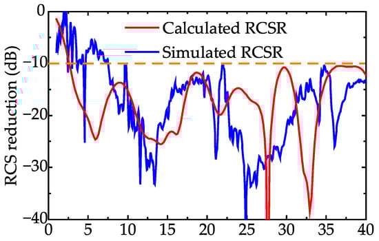
Figure 8.
Calculated and simulated monostatic RCS reduction of the proposed MRPA in the scattering mode.
3.2. Experiment Verification
Based on the preceding analysis, an experimental prototype is fabricated to validate the radiation and scattering performance of the proposed MRPA. An 8 × 8 array prototype with overall dimensions of 156.3 mm × 156.3 mm × 166 mm is manufactured, and the measurement setups are shown in Figure 9. For radiation performance verification, due to hardware limitations, measurements are conducted on a central 4 × 8 subarray. As illustrated in Figure 9a, the prototype is placed inside a microwave anechoic chamber and excited by a vector network analyzer (VNA) through a 1-to-32 power divider and phase shifter to provide in-phase feeding. A standard horn antenna covering 6–18 GHz is employed as the receiving antenna, while a dedicated control circuit independently adjusts the height of each antenna element to realize the prescribed beam-steering states. For scattering performance evaluation, the full 8 × 8 MRPA prototype is configured in the non-radiating mode and mounted on a single-degree-of-freedom turntable, as shown in Figure 9b. The array is illuminated by a normally incident plane wave generated by a transmitting horn antenna, and the backward scattered signal is received by a second horn antenna connected to the VNA to characterize the monostatic RCS response.
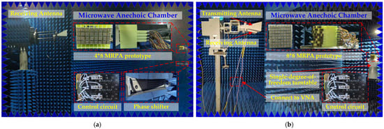
Figure 9.
Experiment configuration of (a) phased array testing, and (b) scattering performance testing.
During assembly, a clearance of approximately 0.3 mm is intentionally maintained at the interfaces between the stepper motors, antenna elements, and guide rails to reduce mechanical friction. This clearance remains below 0.5λ0 across the operational bandwidth and has negligible impact on the measured electromagnetic performance.
For experimental verification, the MRPA prototype is mounted on a controlled turntable and excited to produce a main beam oriented toward (θ0, φ0) = (0°, 0°). Due to hardware constraints, measurements are conducted only on a central 4 × 8 subarray (32 channels in total). From Figure 10a, a peak gain of 18.5 dBi and a cross-polarization isolation of 32.3 dB are observed at 7.9 GHz.
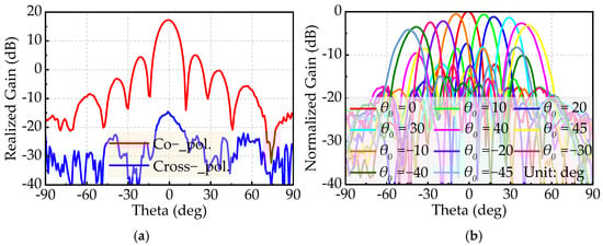
Figure 10.
Measured results of the MRPA prototype: (a) Co-polarization and cross-polarization gains at 7.9 GHz, and (b) normalized radiation patterns for beam scanning from θ0 = −45° to 45°.
Then, 32 stepper motors integrated behind the array are computer-controlled to realize the desired height profile, thereby enabling beam scanning in the XOZ plane over θ0 from −45° to 45°. The measured radiation patterns, normalized to the 18.5 dBi gain obtained at θ0 = 0°, are presented in Figure 10b. Despite the reduced array size and measurement constraints, the measured results exhibit trends consistent with the simulation results, validating the proposed mechanical beam-steering mechanism. The results show that as the scan angle grows, the measured gain progressively decreases and the main beam broadens correspondingly. The most pronounced gain reduction of 4.2 dB occurs at θ0 = −45°, where the sidelobe level also rises. This behavior is mainly caused by ground-plane blockage of lower-height elements, which becomes more severe with increasing height variation at larger scan angles. In addition, unavoidable fabrication and assembly tolerances contribute to the observed radiation-pattern variations. In summary, the experimental results confirm that the proposed MRPA achieves beam steering with a relatively simple structure and feed network while preserving good gain performance, and offers benefits including light weight, compact footprint, and low cost.
The monostatic RCS reduction of the proposed MRPA was experimentally evaluated in the scattering mode, as shown in Figure 11. Owing to the bandwidth limitation of the horn antennas, the measurements were restricted to frequencies below 18 GHz. The measured results show that the RCS reduction exceeds 10 dB over 5.05–7.24 GHz and 7.59–18 GHz. Despite the limited measurement range, the measured RCSR follows the same trend as the calculated and simulated results, validating the effectiveness of the proposed height-induced phase-cancellation mechanism.
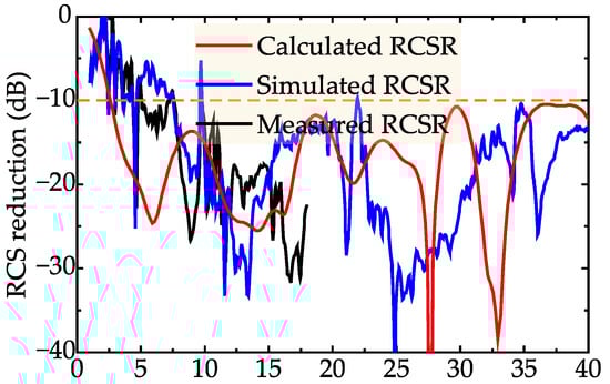
Figure 11.
Measured RCS reduction of the proposed MRPA in the scattering mode.
As summarized in Table 1, the proposed MRPA demonstrates distinctive advantages in both radiation and scattering performance. In terms of radiation, it achieves a realized gain of 21.5 dBi, an aperture efficiency of 87.6%, and a scanning range of ±45° at 7.9 GHz, while maintaining low loss, structural simplicity, and robustness. In terms of scattering, the array exhibits ultra-wideband RCSR across the operational bandwidth. The main innovation of the proposed design lies in the coordinated realization of high-efficiency beam scanning and scattering control within a single mechanically reconfigurable framework, providing a multifunctional capability not addressed in previous mechanically reconfigurable phased arrays.

Table 1.
Performance comparison with previous research.
4. Conclusions
A mechanically reconfigurable phased array antenna with switchable radiation and scattering characteristics has been presented. Height-induced phase modulation is employed to achieve continuous aperture phase control through purely mechanical reconfiguration. In the radiation mode, the proposed array realizes beam steering over ±45° with high realized gain and aperture efficiency, while in the scattering mode, multi-element phase cancellation enables ultra-wideband RCS reduction. Both simulation and experimental results validate the proposed concept. Featuring low loss, structural simplicity, and high robustness, the proposed design is suitable for multifunctional phased array applications requiring efficient beam control and reduced electromagnetic detectability.
Author Contributions
Conceptualization, Y.L. and S.M.; methodology, Y.L. and L.L.; software, S.M.; validation, W.S. and J.S.; formal analysis, M.Q.; investigation, Y.L. and W.S.; resources, L.L. and M.Q.; data curation, S.M.; writing—original draft preparation, Y.L.; writing—review and editing, M.Q. and W.S.; visualization, S.M.; supervision, M.Q. and J.S.; project administration, Y.L. All authors have read and agreed to the published version of the manuscript.
Funding
This research was funded by the National Natural Science Foundation of China, grant number U2141233 and 62171416.
Data Availability Statement
Data are contained within the article.
Conflicts of Interest
The authors declare no conflicts of interest.
References
- Chen, P.; Hong, W.; Zhang, H.; Chen, J.; Tang, H.; Chen, Z. Virtual Phase Shifter Array and Its Application on Ku Band Mobile Satellite Reception. IEEE Trans. Antennas Propag. 2015, 63, 1408–1416. [Google Scholar] [CrossRef]
- Baggen, R.; Holzwarth, S.; Bottcher, M.; Otto, S. Innovative Antenna Front Ends from L-Band to Ka-Band. IEEE Antennas Propag. Mag. 2017, 59, 116–129. [Google Scholar] [CrossRef]
- Chi, Y.-E.; Park, J.; Park, S.-O. Hybrid Multibeamforming Receiver with High-Precision Beam Steering for Low Earth Orbit Satellite Communication. IEEE Trans. Antennas Propag. 2023, 71, 5695–5707. [Google Scholar] [CrossRef]
- Cai, M.; Li, W.; Shi, X.; Zhang, Q.; Liu, H.; Li, Y.; Wan, J.; Gao, S. Design and Simulations of a Novel Ka-Band Isoflux Scanning Phased Array Antenna for GEO Satellites. IEEE Antennas Wireless Propag. Lett. 2024, 23, 738–742. [Google Scholar] [CrossRef]
- Qu, M.; Cheng, Y.; Su, J.; Li, X.; Nayyeri, V. Electromagnetic–Thermal Metasurface-Based Co-Design for HPM Protection, Radar Stealth, and Beam Scanning. IEEE Trans. Microw. Theory Tech. 2025, in press. [Google Scholar]
- Zeng, T.; Jiang, X.; Mo, K.; Chen, T. Electromagnetic Coupling-Based Wide-Beam Antenna Array for Automotive Forward-Looking Radar. IEEE Trans. Antennas Propag. 2025, 73, 6477–6486. [Google Scholar] [CrossRef]
- Saleem, M.K.; Vettikaladi, H.; Alkanhal, M.A.S.; Himdi, M. Lens Antenna for Wide Angle Beam Scanning at 79 GHz for Automotive Short Range Radar Applications. IEEE Trans. Antennas Propag. 2017, 65, 2041–2046. [Google Scholar] [CrossRef]
- Wang, Z.; Tan, Q.; Yang, D.; Fan, K.; Yu, W.; Liu, L.; Luo, G.Q. A Wideband Dual-Circularly Polarized Luneburg Lens Multibeam Antenna Fed by Dual-Linearly Polarized ME-Dipole Antennas. IEEE Trans. Antennas Propag. 2025, 73, 2804–2813. [Google Scholar] [CrossRef]
- Zhang, J.; Zhang, S.; Ying, Z.; Morris, A.S.; Pedersen, G.F. Radiation-Pattern Reconfigurable Phased Array With p-i-n Diodes Controlled for 5G Mobile Terminals. IEEE Trans. Microw. Theory Tech. 2020, 68, 1103–1117. [Google Scholar] [CrossRef]
- Li, J.; Yang, W.; Liu, Y.; Feng, W.; Xue, Q.; Che, W. 66–76 GHz High-Isolation 1-D Wide-Angle Scanning Phased Array Antenna with Bent-Wall Structures. IEEE Antennas Wireless Propag. Lett. 2025, 24, 1193–1197. [Google Scholar] [CrossRef]
- Zhang, Y.; Ogurtsov, S.; Vasilev, V.; Vilenskiy, A.R.; Kishk, A.A.; Ivashina, M.V.; Caratelli, D. Dual-Polarized Dielectric-Filled Cavity Antenna with Air-Gap-Free Metasurface Loading for LTCC-Based 5G-and-Beyond Antenna-in-Package Phased Arrays. IEEE Trans. Antennas Propag. 2025, in press. [Google Scholar]
- Li, J.; Zhu, Y.; Hu, Y.; Hong, W. A Miniaturized Dual-Polarized Active Phased Array Antenna for 5G Millimeter-Wave Applications. IEEE Antennas Wireless Propag. Lett. 2024, 23, 618–622. [Google Scholar] [CrossRef]
- Guirado, R.; Perez-Palomino, G.; de la Rosa, P.; Carrasco, E.; Quintana, X. Electronically Reconfigurable Reflectarray Antenna Based on Single-Layer Liquid Crystal with Independent Dual-Polarization Control. IEEE Trans. Antennas Propag. 2024, 72, 5626–5636. [Google Scholar] [CrossRef]
- Xue, F.; Meng, C.; Li, Y.; Feng, G.; Liu, B.; Wong, S.-W.; Chen, H. A Self-Powered Electronically Reconfigurable Reflectarray Integrated with Solar Cells. IEEE Antennas Wireless Propag. Lett. 2024, 23, 3441–3445. [Google Scholar] [CrossRef]
- Han, J.; Li, L.; Liu, G.; Wu, Z.; Shi, Y. A Wideband 1-Bit 12×12 Reconfigurable Beam-Scanning Reflectarray: Design, Fabrication, and Measurement. IEEE Antennas Wireless Propag. Lett. 2019, 18, 1268–1272. [Google Scholar] [CrossRef]
- Wu, J.; Honari, M.M.; Topözlü, H.; Qiao, S.; Zhao, J.; Booske, J.H.; Behdad, N. A 1-Bit, Electronically Reconfigurable Reflectarray Antenna with an Octave Bandwidth. IEEE Trans. Antennas Propag. 2025, 73, 6499–6511. [Google Scholar] [CrossRef]
- Zhao, J.; Qiao, S.; Topozlu, H.; Wu, J.; Honari, M.M.; Booske, J.H.; Behdad, N. Electronically Reconfigurable Reflectarray Antennas Using 2-Bit Phase-Shift Unit Cells Embedded with Reflecting Circuits. IEEE Trans. Antennas Propag. 2025, 73, 314–328. [Google Scholar] [CrossRef]
- Li, W.; Wang, X.; Wang, Y.; Yan, N.; Yang, G.-M.; Jin, Y.-Q. Single-Beam-Scanning 1-Bit Metasurface with Dual Circular Polarization Based on Hybrid Coding Mechanism. IEEE Trans. Antennas Propag. 2025, 73, 1608–1617. [Google Scholar] [CrossRef]
- Tang, J.; Xu, S.; Yang, F.; Li, M. Design and Measurement of a Reconfigurable Transmitarray Antenna with Compact Varactor-Based Phase Shifters. IEEE Antennas Wireless Propag. Lett. 2021, 20, 1998–2002. [Google Scholar] [CrossRef]
- Liu, Y.; Zhang, H.; Deng, L. Design and Implementation of a Reconfigurable Transmitarray Employing Varactor-Tuned Huygens Elements for Dynamic Beam Shaping. IEEE Antennas Wireless Propag. Lett. 2025, 24, 1542–1546. [Google Scholar] [CrossRef]
- Baladi, E.; Xu, M.Y.; Faria, N.; Nicholls, J.; Hum, S.V. Dual-Band Circularly Polarized Fully Reconfigurable Reflectarray Antenna for Satellite Applications in the Ku-Band. IEEE Trans. Antennas Propag. 2021, 69, 8387–8396. [Google Scholar] [CrossRef]
- Singh, A.K.; Abegaonkar, M.P.; Koul, S.K. Wide Angle Beam Steerable High Gain Flat Top Beam Antenna Using Graded Index Metasurface Lens. IEEE Trans. Antennas Propag. 2019, 67, 6334–6343. [Google Scholar] [CrossRef]
- Zhang, G.; Su, M.; Zhang, Y.; Wang, A.; Pan, C. Methodology and Implementation of Beam Steering Using C-Shaped Split Rings for Fabry–Perot Antennas. IEEE Trans. Antennas Propag. 2023, 71, 2268–2277. [Google Scholar] [CrossRef]
- Farahbakhsh, A.; Zarifi, D.; Mrozowski, M. A Ku-Band Mechanically Reconfigurable Slot Array Antenna Using Gap Waveguide Technology. IEEE Trans. Antennas Propag. 2025, 73, 7510–7520. [Google Scholar] [CrossRef]
- Sanchez-Olivares, P.; Masa-Campos, J.L.; Muriel-Barrado, A.T.; Villena-Medina, R.; Fernandez-Romero, G.M. Mechanically Reconfigurable Linear Array Antenna Fed by a Tunable Corporate Waveguide Network with Tuning Screws. IEEE Antennas Wireless Propag. Lett. 2018, 17, 1430–1434. [Google Scholar] [CrossRef]
- Polo-López, L.; Masa-Campos, J.L.; Muriel-Barrado, A.T.; Sanchez-Olivares, P.; Garcia-Marin, E.; Córcoles, J.; Ruiz-Cruz, J.A. Mechanically Reconfigurable Linear Phased Array Antenna Based on Single-Block Waveguide Reflective Phase Shifters with Tuning Screws. IEEE Access 2020, 8, 113487–113497. [Google Scholar] [CrossRef]
- Teng, M.; Yu, S.; Kou, N.; Ding, Z.; Zhang, Z. Mechanical Beam Steering Array Antenna with Tunable Height. IEEE Antennas Wireless Proapag. Lett. 2022, 21, 2293–2297. [Google Scholar] [CrossRef]
- Henderson, K.Q.; Disharoon, W.; Ghalichechian, N. Toward High-Power Beam-Steerable Reflectarrays Using Tunable-Height Dielectric. IEEE Trans. Antennas Propag. 2023, 71, 2487–2496. [Google Scholar] [CrossRef]
- Yang, X.; Xu, S.; Yang, F.; Li, M.; Fang, H.; Hou, Y.; Jiang, S.; Liu, L. A Mechanically Reconfigurable Reflectarray with Slotted Patches of Tunable Height. IEEE Antennas Wireless Propag. Lett. 2018, 17, 555–558. [Google Scholar] [CrossRef]
- Yin, L.; Yang, P.; Gan, Y.; Yang, F.; Yang, S.; Nie, Z. A Low Cost, Low in-Band RCS Microstrip Phased-Array Antenna with Integrated 2-bit Phase Shifter. IEEE Trans. Antennas Propag. 2021, 69, 4517–4526. [Google Scholar] [CrossRef]
- Wang, B.; Lin, X.Q.; Kang, Y.X.; Hu, R.X. Low-RCS Broadband Phased Array Using Polarization Selective Metamaterial Surface. IEEE Antennas Wireless Propag. Lett. 2022, 21, 94–98. [Google Scholar] [CrossRef]
- Qu, M.; Li, Y.; Hao, F.; Su, J. A Low-Cost Scalable Stepper-Motor-Driven Metasurface with Programmable Height Control for Dynamic RCS Modulation. IEEE Microw. Wireless Techn. Lett. 2025, in press. [Google Scholar] [CrossRef]
- Hyde, R. The Book of I2C: A Guide for Adventurers; No Starch Press: San Francisco, CA, USA, 2022. [Google Scholar]
Disclaimer/Publisher’s Note: The statements, opinions and data contained in all publications are solely those of the individual author(s) and contributor(s) and not of MDPI and/or the editor(s). MDPI and/or the editor(s) disclaim responsibility for any injury to people or property resulting from any ideas, methods, instructions or products referred to in the content. |
© 2026 by the authors. Licensee MDPI, Basel, Switzerland. This article is an open access article distributed under the terms and conditions of the Creative Commons Attribution (CC BY) license.