Abstract
Converters play a critical role in wind power generation systems, with their reliability directly impacting system stability and operational efficiency. To address the challenges posed by increased thermal load fluctuations due to solder layer aging in insulated gate bipolar transistor (IGBT) modules in converters, this paper proposes an aging-aware multi-objective thermal management (AAMO-TM) strategy to enhance the performance of aging modules. An improved junction temperature estimation model is developed, incorporating coordinated control of switching frequency and gate drive resistance to account for the dynamic thermal behavior of IGBT modules during aging. Pareto and hierarchical optimization techniques are employed to resolve the multi-objective problem of excessive junction temperature suppression, junction temperature fluctuation smoothing, and power quality improvement. Experimental results demonstrate that our proposed AAMO-TM strategy outperforms a competing strategy at temperature fluctuation by a large margin (up to 59.4%). Our proposed strategy significantly enhances the thermal stability of aging IGBT modules while effectively suppressing grid-connected current harmonics. This study provides valuable theoretical insights and practical guidance for achieving the stable operation of wind turbines and delivering high-quality power output.
1. Introduction
Wind energy has emerged as a preferred renewable energy source for power generation, owing to its widespread availability, environmental benefits, and abundant reserves. However, wind power generation systems are often situated in remote or offshore locations, where operating conditions are complex. In offshore environments, factors such as variable wind speeds, humidity, and temperature, as well as extreme weather events like thunderstorms and hurricanes, can significantly impact system performance. Additionally, maintenance of faulty equipment in these locations is more challenging, and the operational and maintenance costs are typically two to three times higher than those of onshore systems [1]. Consequently, enhancing system reliability is critical for reducing maintenance costs and improving economic performance [2,3].
As a key component linking the turbine to the grid, the reliability of the converter in a wind energy conversion system plays a significant role in the overall system performance [4,5]. The IGBT module in the wind power converter is the most critical component, being the leading cause of thermal-related failures. It not only constitutes approximately 40% of the total system cost but also accounts for over 60% of all failures within the system [1]. Among the various failure causes, temperature steady state and cyclical variations are the most prominent, as illustrated in Figure 1 [6], with temperature-induced failures representing 55% of the total failures [7]. Research has shown that fluctuations in junction temperature accelerate IGBT module aging, causing thermal stresses and material interface degradation. These factors eventually lead to failures in the solder layer and bonding leads, potentially resulting in system shutdowns or catastrophic failures [8,9]. Moreover, it has been demonstrated that for every 10 °C increase in the junction temperature of a silicon device within its rated operating range, its lifetime is reduced by approximately 50% [10]. In wind grid-side converters, high-frequency and fundamental-frequency junction temperature fluctuations have a relatively minor impact on IGBT lifetime, while low-frequency temperature fluctuations are the primary contributing factor [11,12]. Therefore, effective thermal management of IGBTs is crucial for enhancing the overall reliability of the system.
Figure 1.
Percentage distribution of contributing factors to IGBT module failure.
Conventional thermal management strategies primarily aim to control the junction temperature by compensating for or reducing power losses. Since switching losses are highly dependent on the switching frequency, adjusting the frequency provides a feasible approach to managing the junction temperature. For instance, hysteresis control limits are established using known boundary values for junction temperature fluctuations in [13]. When the upper hysteresis limit is exceeded, the switching frequency is reduced. Conversely, when the amplitude of the junction temperature fluctuations fall to the lower limit, the switching frequency returns to its initial set value. This mechanism causes the switching frequency to oscillate between the maximum and minimum set values, effectively controlling the junction temperature fluctuations within the range of 45 °C to 50 °C. This method results in a reduction of the maximum junction temperature of the inverter by approximately 30%. A comprehensive approach is proposed in [14] that considers both junction temperature and fluctuations within dual boundaries. When either the junction temperature or its fluctuations exceed the upper threshold, the switching frequency is reduced to its minimum to achieve thermal control. Experimental results indicate that with the upper limit of junction temperature set to 95 °C, a temperature variation of approximately 17 °C is observed during specific time intervals. While reducing the switching frequency is effective in regulating junction temperature, achieving the desired suppression typically requires a significant reduction to the lower limit, which can substantially degrade the converter’s control performance. This not only reduces the power generation efficiency of the converter [15] but also decreases the quality of the electrical energy output, leading to an increase in total harmonic distortion (THD) [16].
In [17,18], it is shown that power loss can be controlled by adjusting the gate drive resistance, particularly effective in high-current scenarios. Furthermore, ref. [19] introduces a novel multi-level gate driver topology that allows for different drive resistance values for each phase of the IGBT switching transient. This optimization reduces the IGBT turn-on and turn-off losses by 9% and 26%, respectively, offering a new approach for thermal management of IGBT modules. In [20], a switchable gate resistor network is proposed to adjust the gate resistance based on the amplitude of the output AC voltage, thereby regulating junction temperature fluctuations. Additionally, this design expands the adjustable range of gate resistance in the power module from 1.8 Ω to 18 Ω. Dynamic control of gate resistance can reduce junction temperature fluctuations without adversely affecting output power quality. However, these methods are generally designed for ideal IGBT modules and do not account for the impact of aging on thermal parameters. Over extended operation, the thermal properties of IGBT modules evolve due to accumulated fatigue, making traditional single-parameter strategies less effective in suppressing temperature fluctuations and maintaining system reliability [21].
To address these challenges, this paper proposes an aging-aware multi-objective thermal management strategy that considers junction temperature suppression, fluctuation smoothing, and power quality requirements. First, an enhanced junction temperature estimation model is developed, incorporating solder layer fatigue characteristics for more accurate predictions in aged IGBT modules. Second, a nonlinear system of equations is constructed to model the relationships among mean junction temperature, temperature fluctuations, and output current THD under aging conditions, based on switching frequency and gate resistance. Third, Pareto and hierarchical optimization techniques are introduced to identify optimal combinations of control parameters, generating a decision vector for effective thermal management. The proposed strategy suppresses junction temperature rise, smooths temperature fluctuations, and improves converter output power quality. Finally, comparative studies with conventional strategies validate the superior performance of the proposed method in mitigating thermal stress and enhancing power quality for aging IGBT modules.
2. Preliminaries
2.1. Analysis of the Impact of Module Aging Processes on Thermal Management
Failure analysis of power devices reveals that solder layer fatigue is one of the primary failure modes of IGBT modules, which is caused by the mismatch between the alternating thermal stresses and the thermal expansion coefficients of the materials in each layer. In IGBT devices, the solder layer is typically divided into the chip solder layer and the backplane solder layer. The commonly used solder materials include tin–lead alloy, tin–silver alloy, and nano-silver, which exhibit significant differences in their coefficients of thermal expansion compared to the materials at both ends. The chip solder layer, being closer to the chip and farther from the heat sink, experiences more concentrated thermal stress, resulting in generally lower reliability [22]. Solder layer failure primarily manifests in two forms: solder layer voids and solder layer cracks. The edges of the solder layer are regions of concentrated stress distribution, making them prone to crack formation. These cracks tend to propagate under repeated thermal cycling stress, ultimately leading to solder layer failure. Furthermore, during the production process, initial micro-voids may already exist in the solder layer. The cyclic shear strain and spatial temperature gradient induced by temperature variations cause these voids to enlarge over time, eventually leading to solder layer failure [23]. As shown in Figure 2, once damage or cracks occur in the solder layer, the thermal resistance of the IGBT module increases, with the increase becoming approximately exponential as the module ages. Based on the mathematical relationship between junction temperature and thermal resistance, it is evident that, even under the same electrical conditions, the magnitude and fluctuation of thermal loads experienced by the IGBT module will increase, thereby accelerating the progression of damage [24]. This results in a positive feedback loop in the aging process, exacerbating thermal stresses and accelerating the depletion of the module’s operational life. In the thermal management of IGBT modules, neglecting the effects of aging can lead to an underestimation of the thermal load, thereby significantly overestimating the module’s lifespan. Consequently, the actual performance in terms of junction temperature fluctuation smoothing and temperature suppression is often unable to meet the expected targets.
Figure 2.
Effect of aging process of IGBT module on thermal parameters.
For a given loss power, the increase in the device’s thermal load is proportional to the increase in thermal resistance. Even during transient processes, the impact of solder layer failure on the thermal capacitance is negligible, allowing for the effect of thermal capacitance on the heat transfer process to be disregarded [25]. Therefore, to quantitatively assess the aging process of the device, thermal resistance can be chosen as the damage evaluation criterion. Based on the parameters observed at the time of module failure, a 50% increase in thermal resistance (corresponding to a maximum possible increase of 50% in junction temperature) is defined as the failure criterion for the module. At this point, the aging coefficient is defined as . The thermal resistance of the IGBT module is calculated using the following formula [24]:
where is the initial thermal resistance value, and and are the cyclic scaling factor and temperature stress factor, respectively.
In this study, a grid-side three-phase two-level voltage-source converter connected to a permanent magnet synchronous generator (PMSG) is used as an example. The equivalent thermal network model of the converter is developed in MATLAB (R2023b), as illustrated in Figure 3. In the model, and represent the junction temperatures of the IGBT and diode, respectively; and denote the case temperatures of the IGBT and diode; corresponds to the heat sink temperature; and is the ambient temperature. Thermal impedances and represent the steady-state thermal impedances of the IGBT and diode, while and are the thermal impedances from the IGBT and diode case to the heat sink. denotes the thermal impedance of the heat sink. It is assumed that the reference temperature points for the IGBT and diode are identical. Additionally, and serve as the input excitation signals in the thermal network model [26,27].
Figure 3.
Equivalent thermal network model of the converter.
For a three-phase inverter employing space vector pulse width modulation (SVPWM), the junction temperature of the IGBTs in the grid-side converter is calculated using the equivalent thermal network model, as expressed in Equations (2)–(6) [28,29,30]:
In this context, represents the power loss of the IGBT, while and denote the switching loss and conduction loss, respectively. and correspond to the energy consumption of the device during the turn-on and turn-off cycles, is the switching frequency of the IGBT, represents the on-state saturation voltage, is the collector current, and is the collector voltage. The steady-state thermal impedance of the case, , is equal to the sum of the thermal impedances of the thermal networks, while represents the thermal impedance of the order RC network, consisting of the thermal resistance and the thermal capacitance . As the aging of the device primarily manifests as an increase in thermal resistance due to solder layer fatigue, the second-order thermal resistance in the fourth-order thermal network can be modeled as a variable resistor. The value of this thermal resistance can be adjusted dynamically based on the aging level of the device.
2.2. Comprehensive Evaluation System of Thermal Management Effectiveness
Existing research has demonstrated that reducing junction temperature fluctuations through thermal management, denoted as , can effectively extend the lifespan of IGBT modules [31]. Consequently, serves as a critical metric for evaluating the effectiveness of thermal management strategies. However, thermal management strategies that focus solely on often fall short of achieving the desired suppression of junction temperature fluctuations.
During certain phases of the thermal cycle, the magnitude of the junction temperature variation may exceed the system-specified upper limit, denoted as [32]. Figure 4 illustrates two complete thermal cycles of an IGBT in a wind power converter, each exhibiting the same junction temperature variation. However, the difference between the maximum junction temperature and the average junction temperature reaches 20 °C, which introduces additional complexity to IGBT thermal management [16]. To mitigate the risk of overheating and damage to the module, thermal management control must incorporate both and either or . Their mathematical expressions are presented in Equations (7) and (8).
Figure 4.
Schematic diagram of IGBT thermal cycling in wind turbine converter.
However, during the process of leveling IGBT junction temperature, the reduction of and may introduce other negative effects. For instance, when employing the switching frequency regulation method, selecting a lower switching frequency to reduce junction temperature fluctuations can extend the lifespan of IGBTs. However, this approach decreases converter efficiency and increases the total harmonic distortion (THD) of the three-phase output current, thereby degrading power quality.
As illustrated in Figure 5, reducing the upper control limit of junction temperature fluctuations results in a gradual decrease in IGBT switching frequency. However, the growth rate of THD () increases concurrently [16]. Consequently, THD must be incorporated into the evaluation metrics when designing a thermal management strategy. Addressing the dual objectives of smoothing junction temperature fluctuations while ensuring the converter’s output power quality presents a significant challenge in the thermal management of IGBTs.
Figure 5.
Relationship between the upper limit of the junction temperature fluctuation and the switching frequency (THD growth rate): (a) Trend of the switching frequency when the upper limit of junction temperature fluctuation grows; (b) Trend of the THD growth rate.
The expressions for THD and its growth rate are given as follows:
Here, represents the RMS value of the 50 Hz fundamental component in the converter output current, denotes the RMS value of the harmonic components that are no greater than an integer multiple of the H-order, and signifies the total harmonic distortion after the implementation of thermal management.
3. Proposed Thermal Management Strategy
To address the challenges posed by aging factors on the thermal management effectiveness of IGBT power devices, this paper introduces an aging-aware multi-objective thermal management (AAMO-TM) methodology. The proposed AAMO-TM approach employs Pareto optimization and hierarchical optimization to regulate switching frequency and gate drive resistance, enabling comprehensive thermal management of IGBTs across different aging stages. By integrating these optimization techniques, AAMO-TM ensures enhanced thermal performance and reliability of IGBT modules throughout their aging process.
3.1. Thermal Management Control Parameters and Their Constraints
In this study, switching frequency and gate drive resistance are chosen as the two key parameters for thermal management. Prior to implementing thermal management, it is essential to define the adjustable ranges of these parameters to ensure effective and reliable operation.
3.1.1. Switching Frequency Constraints
The switching frequency is a critical parameter influencing the operation of the converter. When adjusting the switching frequency, it is essential to balance the output waveform quality of the converter and the switching loss of the IGBT module. This ensures compliance with the technical specifications for grid-connected renewable energy systems while avoiding excessively high switching frequencies that could lead to the junction temperature of the IGBT module exceeding its allowable limit. The permissible range of the switching frequency can be expressed as follows:
Among them, and represent the upper and lower boundaries of the switching frequency range, respectively; denotes the minimum switching frequency at which the output current satisfies the THD requirements for grid-connected systems; and are the maximum power losses of the IGBT and diode within the module under the highest junction temperature; and represent the conduction losses of the IGBT and diode; is the energy consumption during IGBT switching; is the reverse recovery energy consumption during diode switching; and is the voltage change rate of collector and emitter.
3.1.2. Driving Resistance Constraints
To mitigate resonant oscillations in the IGBT gate drive circuit and prevent unintended conduction of the IGBT, it is essential to ensure that the gate resistance satisfies the following conditions [33]:
where represents the total parasitic inductance in the gate drive loop; denotes the approximate input capacitance of the IGBT; is the threshold voltage for IGBT conduction; indicates the negative drive voltage; corresponds to the parasitic capacitance between the gate and collector, as shown in Figure 6; and is the rate of change of the collector-emitter voltage.
Figure 6.
IGBT equivalent circuit.
3.2. Thermal Management Decisions Based on Multi-Objective Optimization
3.2.1. Objective Function
In the thermal management process, a trade-off exists between the smoothing effect of the IGBT junction temperature and the quality of the converter’s output power. Achieving simultaneous optimization of these conflicting objectives falls under the scope of multi-objective problem solving, which can be formulated as follows:
Here, represents the p-dimensional decision vector, while denotes the n-dimensional objective vector. The functions and correspond to the inequality and equality constraints of the multi-objective optimization problem, respectively. Consequently, this study reformulates the conventional thermal management challenge as a multi-objective optimization problem. A novel thermal management strategy is subsequently developed through multi-objective optimization to achieve synergistic enhancement of junction temperature suppression and output power quality.
In this study, a PMSG-based wind power generation system is modeled and simulated using the MATLAB/Simulink platform. Thermal simulations are conducted for a 1700 V/600 A IGBT module within the system’s converter. The junction temperature of the IGBT and the output three-phase currents are collected under various aging conditions, given a specific wind speed and ambient temperature. A 10% increment in thermal resistance is adopted as the aging gradient, with the aging factor . The switching frequency is discretized in 100 Hz steps within the range of [, ], while the gate drive resistance is discretized in 0.2 Ω steps within the range of [, ].
A total of 5915 simulation datasets are generated, serving as modeling examples for the three objective functions: , , and . Based on these data, multiple regression analysis is performed using Minitab software 22 to fit the data and establish a model. The model takes the IGBT aging degree, switching frequency, and gate drive resistance as inputs, and outputs the average junction temperature, junction temperature deviation, and total harmonic distortion of the output three-phase current. The resulting model is as follows:
where represents the model for the average junction temperature; denotes the model for the junction temperature variation; and corresponds to the model for total harmonic distortion. When the aging factor is specified, the aforementioned model can be expressed as follows:
In this context,
The matrix equation is generated as follows:
where the coefficient matrix of the equation is denoted as .
In this study, the regulation objectives are defined as the minimization of the mean junction temperature, the junction temperature variation, and the total harmonic distortion. Consequently, this multi-objective optimization problem can be formulated as follows [34]:
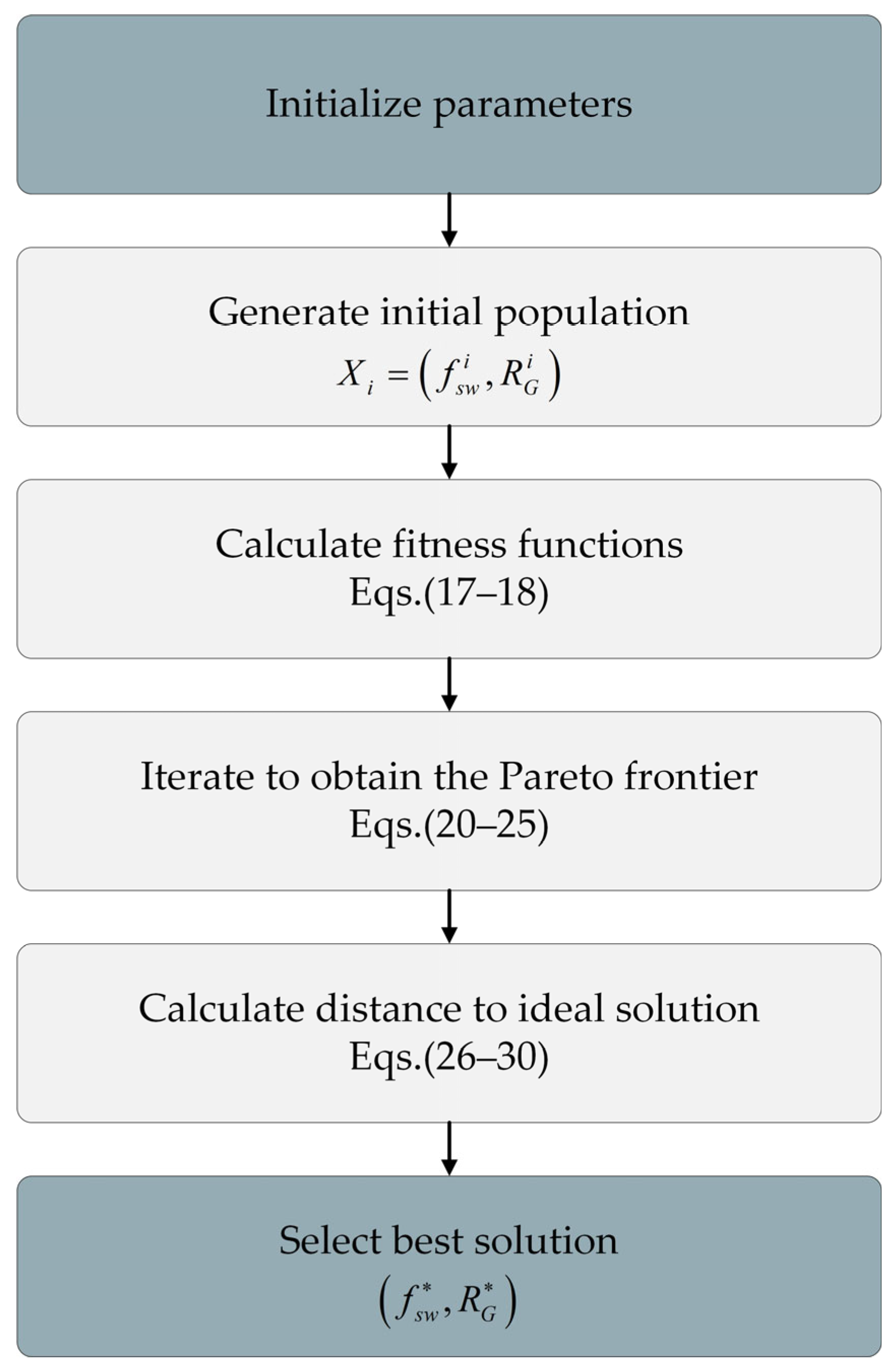
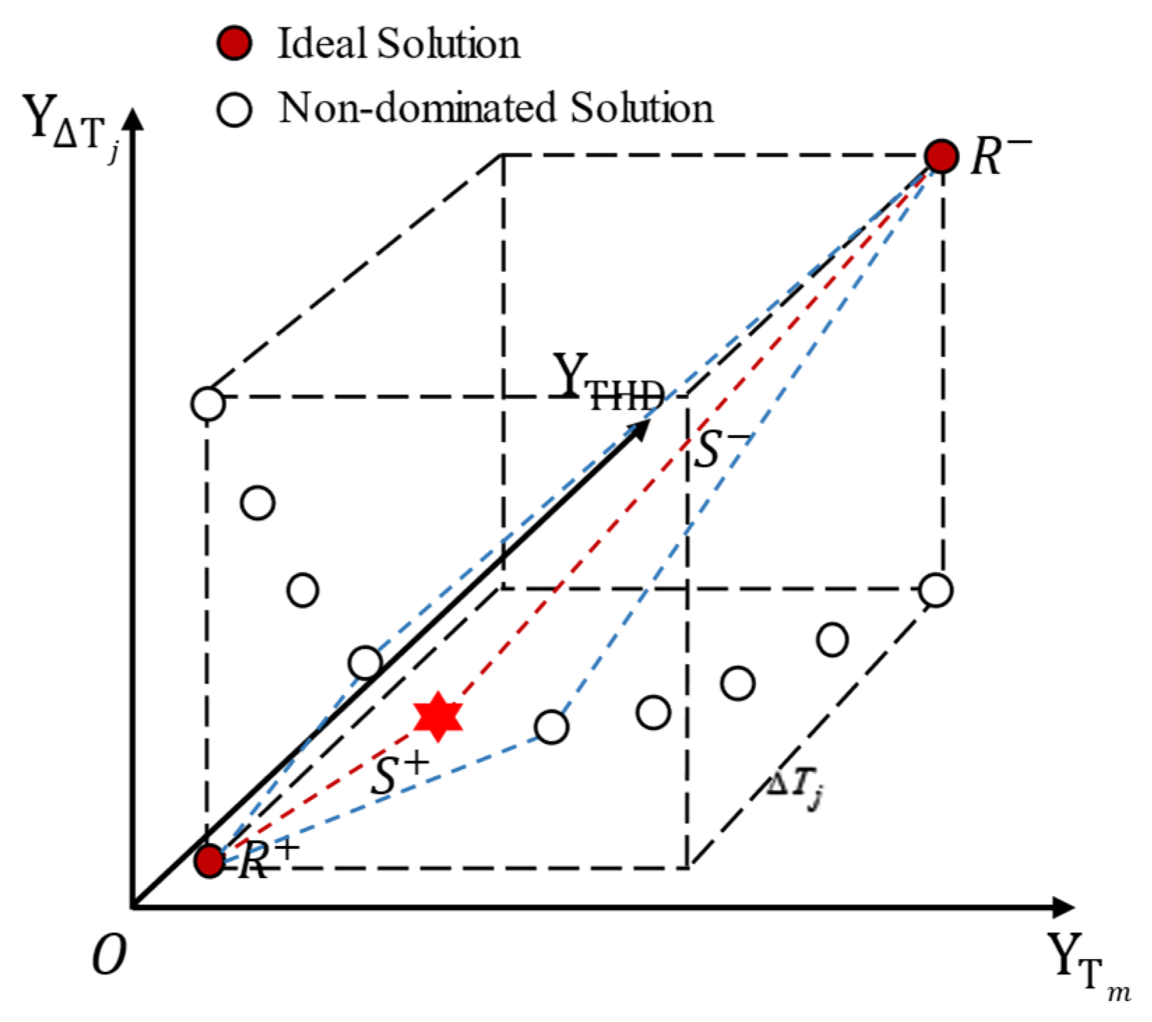
3.2.2. MOGWO-TOPSIS Based Thermal Management Decision
The proposed thermal management strategy integrates the multi-objective grey wolf optimization (MOGWO) algorithm with the technique for order of preference by similarity to ideal solution (TOPSIS) to address the aforementioned multi-objective optimization problem [35,36]. Figure 7 shows the thermal management decision-making process based on MOGWO-TOPSIS. This approach identifies the optimal parameter combinations for switching frequency and gate drive resistance, generating an IGBT thermal management strategy tailored to the specified aging state. The specific steps are outlined as follows:
Figure 7.
Thermal management decision-making flowchart based on MOGWO-TOPSIS.
First, the upper and lower limits of and are determined according to the environment, system conditions, and the parameters in the datasheet, which are labeled as , , , and , respectively; meanwhile, the coefficient matrix is determined, and the objective functions , , and are generated. We set the number of populations and the maximum number of iterations and randomly generate as the initial population in the rectangular area defined by , , and .
We calculate the fitness of each individual , , and , and, sort them, non-dominated, where the individual dominates under the condition that the archive is generated according to the set consisting of non-dominated solutions for , , and such that . The optimal individual , the second best individual , and the third best individual are determined sequentially, where , , , and are the leader selection functions. Here, is the archive without ; and is the archive after removing and at the same time.
According to Equations (20)–(25), the position of the gray wolf, , is updated. Here, represents the current position of the gray wolf, while and are coefficient vectors that dynamically vary with the number of iterations. The parameter decreases from 2 to 0 as the number of iterations increases, and and are random vectors within the range [0, 1] [34].
The next generation population is continuously updated until the maximum number of iterations, , is reached. During this process, the external archive effectively preserves the best non-dominated solutions obtained so far. Ultimately, the non-dominated solution set, , is output. Based on the solutions in and their corresponding objective function values, a decision matrix C of size is generated and normalized to form the matrix R, such that . According to the aging factor, the weights corresponding to the objective functions , , and are set to , , and , respectively. A weight vector is then generated, and the weighted normalized matrix D is computed as . Here, , , and are the elements of the matrices C, R, and D, respectively, and is the size of the archive , where and , with .
Additionally, the weights of the three objective functions can be adjusted based on the varying aging degrees of the IGBT modules. For instance, during the pre-aging phase of the module, the value of can be appropriately increased to ensure the system maintains good output power quality. Conversely, during the advanced aging phase of the module, can be minimized to prioritize junction temperature suppression and smoothing of junction temperature fluctuations, aiming to extend the IGBT lifespan as much as possible. In this stage, the primary objective is to balance thermal management while ensuring that the power quality meets the grid-connection requirements.
Next, the positive ideal solution and the negative ideal solution are determined according to Equations (26) and (27). The Euclidean distances and between each particle in the and and , respectively, are then calculated using Equations (28) and (29). Here, represents the distance between the non-dominated solution and the positive ideal solution, while represents the distance between the non-dominated solution and the negative ideal solution.
The relative proximity S of each solution is then calculated according to Equation (30) and illustrated in Figure 8 to score each solution. A larger proximity indicates that the solution is closer to the positive ideal solution, and consequently, its comprehensive score is higher [35]. Finally, the solutions are ranked in descending order based on their relative proximity, and the solution with the highest relative proximity is selected and mapped into the decision space. This corresponds to the optimal thermal management decision vector , which is depicted as the red hexagonal symbol in Figure 8.
Figure 8.
Schematic of the process of searching for thermal management decision values from the Pareto frontier using the TOPSIS algorithm.
4. Simulation and Discussion
To verify the impact of device aging on thermal management and the effectiveness of the proposed thermal management strategy in suppressing and smoothing the junction temperature of aging IGBT modules, this paper uses Infineon’s 1700 V/600 A IGBT module for experimental validation and analysis. The thermal network parameters of the IGBT module are provided in Table 1.
Table 1.
IGBT module thermal network parameters.
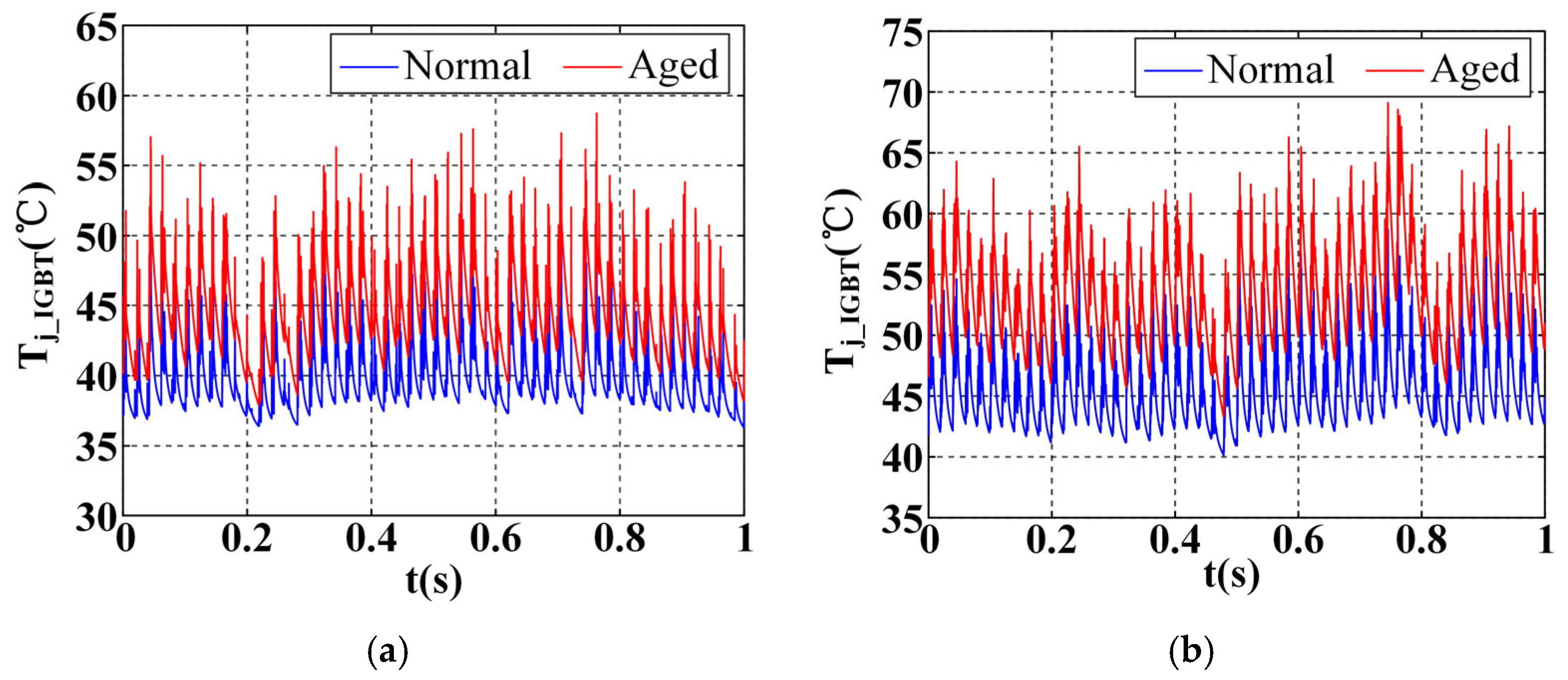
4.1. Validation of the Impact of Module Aging on Thermal Management Effectiveness
To evaluate the impact of the increase in thermal resistance due to device aging on the effectiveness of thermal management, this paper compares the junction temperatures of IGBTs in both normal and solder layer fatigue states under the same thermal management strategy. The tests are conducted under the conditions of wind speed and ambient temperature °C, using switching frequency adjustment (SFA) and drive resistance adjustment (DRA) methods for thermal management of the IGBT modules, with aging factors of 0 and 0.35, respectively. From Figure 9 and Table 2, it is evident that the junction temperature of aging IGBTs is significantly higher than that of normal IGBTs, regardless of whether the SFA or DRA method is employed. When the SFA strategy is applied, the peak junction temperature and the average junction temperature of the aging IGBTs increase by 10.4% and 11.6%, respectively. Furthermore, the junction temperature fluctuation exhibits a more pronounced increase of 23.4%. Under the same conditions, when the DRA strategy is utilized, the , , and of the aging module increase by 16.8%, 17.5%, and 35.8%, respectively. These results highlight the significant impact of aging on the thermal performance of IGBTs under different thermal management strategies. It suggests that the junction temperature suppression and temperature fluctuation smoothing effects of the thermal management strategy are hindered by device aging. Therefore, the comprehensive thermal management strategy for IGBTs proposed in this paper, which accounts for the aging process of the device, is found to be effective.
Figure 9.
Comparison of normal and aged IGBT junction temperature waveforms after SFA and DRA modulation: (a) with SFA; (b) with DRA.
Table 2.
Junction temperature data of normal and aged IGBTs after SFA and DRA modulation.
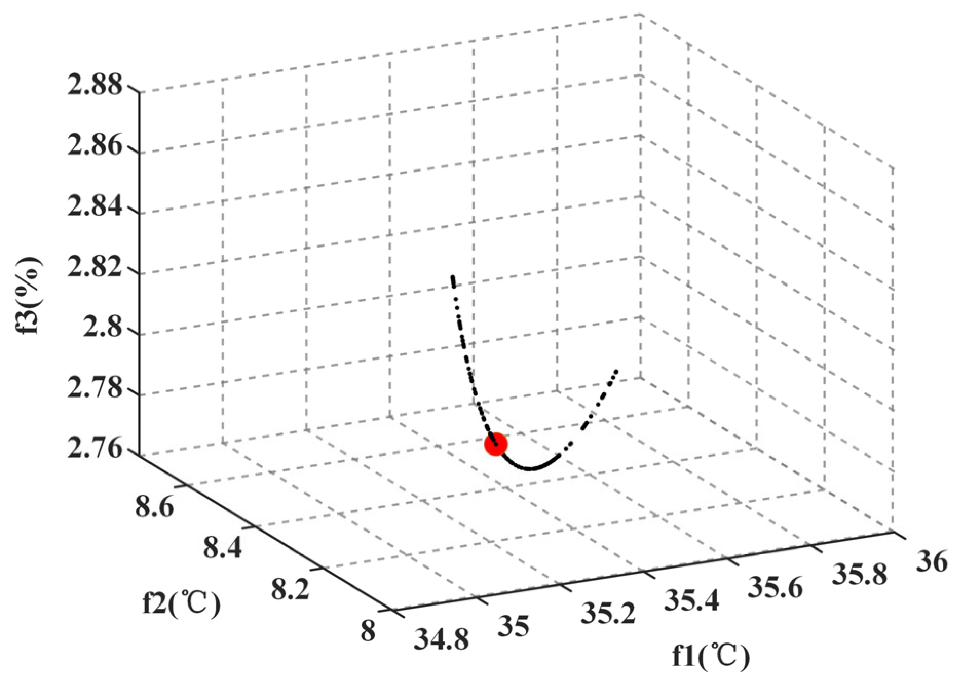
4.2. Verification and Analysis of the AAMO-TM Method
In order to verify the effectiveness of the improved thermal management strategy for the aging IGBT module, an aging factor of is considered in this study. Under the conditions of wind speed and ambient temperature °C, the upper and lower limits of the switching frequency and gate resistance are set as , , , and . The parameters in the coefficient matrix are determined as shown in Table 3, which are used to generate the three objective functions , , and . The population size is set to , and the maximum number of iterations is set to . An initial population of 300 individuals is randomly generated within the rectangular area defined by , , , and , where each individual , . The fitness of each individual is calculated using the objective functions , , and , and individuals are sorted based on non-dominated ordering. An archive is created from the non-dominated solutions, with an archive size , and the top three individuals in the fitness ranking, denoted as , , and , are stored. The population is iteratively updated, and the position, fitness calculations, and sorting are repeated while updating the archive, until the maximum number of iterations is reached. The final non-dominated solution set, is then output, along with the corresponding points and their objective function values. The objective function curve is represented as a black curve in Figure 10.
Table 3.
Parameters of the thermal management-coupled model coefficient matrix.
Figure 10.
Schematic diagram of selecting thermal management decision values from the Pareto front.
Based on the solutions in and their corresponding objective function values, a decision matrix C of size is generated and normalized to form matrix R. According to the literature [34], the weights , , and corresponding to the objective functions , , and are set as 0.4, 0.4, and 0.2, respectively, yielding a weight vector . The weighted normalized matrix D is then computed as , where , and . The Euclidean distances between the positive and negative ideal solutions, and , and the particles with the values and are calculated as and , respectively. The relative proximity is then used as the criterion to score all solutions and sort them in descending order. The solution vector corresponding to the highest score is selected as the thermal management decision vector. The relative proximity is used to rank all solutions, and the highest-ranking solution, with , is chosen as the thermal management decision vector , which is represented as a red sphere in Figure 10. The optimal values are . Finally, the switching frequency and gate drive resistance of the IGBT module are adjusted according to this decision vector to achieve junction temperature suppression and smoothing.
Figure 11 illustrates a comparison of IGBT junction temperature waveforms over a 1-s period under different thermal management strategies, including the proposed AAMO-TM method, as well as the SFA and DRA methods. As shown in Figure 11a, without any thermal management (WTM), the junction temperature fluctuates significantly, ranging from 55 °C to 105 °C, with a large peak-to-valley difference and a high average temperature. This substantial fluctuation could result in overheating and reduced device lifetime. In contrast, Figure 11b,c show the results of the SFA and DRA methods, respectively. Both methods effectively suppress the temperature fluctuations, limiting them to within 20 °C and reducing the maximum junction temperature to approximately 55 °C. These methods reduce thermal stress on the IGBT module, demonstrating their effectiveness in thermal management. Finally, the AAMO-TM strategy (Figure 11d), which was proposed in this study, demonstrates the most effective thermal management. Compared to SFA and DRA, AAMO-TM demonstrates significantly improved junction temperature suppression and fluctuation smoothing. The low-frequency temperature fluctuations are successfully reduced to within 10 °C, and the average temperature is maintained around 35 °C. The improved smoothness of the temperature curve leads to a significant reduction in thermal stress on the module, enhancing system stability and ensuring better long-term performance.
Figure 11.
Comparison of IGBT junction temperature waveforms under different thermal management strategies: (a) with WTM; (b) with SFA; (c) with DRA; (d) with AAMO-TM.
To verify the impact of the thermal management strategy proposed in this paper on the power quality of the system’s output three-phase alternating current (AC), the three-phase current waveforms corresponding to the time period after the junction temperature waveforms stabilize are extracted, as shown in Figure 12. Since the amplitudes and frequencies of the three-phase AC currents—labeled a, b, and c—are equal and differ only by a 120° phase shift, the a-phase current is selected for analysis. The total harmonic distortion (THD) of this phase current during the time period is used to characterize the power quality. As shown in Figure 12a,c, no change in THD is observed before and after drive resistance adjustment (DRA), indicating that drive control does not affect power quality. However, under the influence of the thermal management strategy proposed in this paper (Figure 12d), the THD value is reduced by 0.26% compared to the switching frequency regulation method (Figure 12b). This reduction mitigates the negative effects of thermal management on the output current and achieves compensation for the power quality.
Figure 12.
Localized (single-cycle) magnified view of system output three-phase currents under different thermal management strategies: (a) with WTM; (b) with SFA; (c) with DRA; (d) with AAMO-TM.
Table 4 and Table 5 present a performance comparison of different thermal management strategies. It can be observed that the two thermal management methods, SFA and DRA, exhibit distinct advantages and disadvantages in terms of junction temperature suppression and fluctuation smoothing. The SFA method demonstrates superior junction temperature suppression, with improvements of 1.2% in maximum junction temperature and 5.8% in average junction temperature suppression compared to DRA. In contrast, the DRA method excels in junction temperature fluctuation smoothing, achieving a 5.4% increase in smoothing degree over SFA.
Table 4.
Comparison of performance metrics for different thermal management strategies.
Table 5.
Comparison of the proposed method with SFA and DRA performance.
The thermal management strategy proposed in this paper, which combines switching frequency and drive resistance adjustment, effectively integrates the strengths of both methods in junction temperature control. The proposed approach achieves a 13.6%, 6.6%, and 25.1% improvement in maximum junction temperature (), average junction temperature () suppression, and junction temperature fluctuation () smoothing, respectively, compared to SFA. It also improves these parameters by 14.8%, 12.4%, and 19.7%, respectively, compared to DRA, demonstrating superior thermal management performance. This approach offers significant advantages in enhancing IGBT reliability and extending service life.
Furthermore, the THD value of the grid-side output three-phase current in the system controlled by the proposed method is reduced by 0.26% compared to the switching frequency regulation method. This results in a notable improvement in the power quality of the new grid-connected energy system. Additionally, the switching frequency of the proposed method is increased by 27.96% relative to the traditional switching frequency regulation method, ensuring greater efficiency of the key switching device, the IGBT, in the converter.
5. Conclusions
This paper proposes an aging-aware multi-objective thermal management (AAMO-TM) strategy to address the thermal instability and reliability degradation of aging Insulated-Gate Bipolar Transistor (IGBT) modules in wind power converter systems. The strategy integrates coordinated control of switching frequency and gate drive resistance, leveraging Pareto-based multi-objective optimization and hierarchical optimization techniques to simultaneously achieve three key objectives: suppressing junction temperature rise, minimizing temperature fluctuations, and improving power quality.
A nonlinear thermal and power quality model is developed to capture the impact of aging on thermal resistance and its effect on junction temperature. The model accurately describes the relationship between mean junction temperature, temperature fluctuations, and converter output current total harmonic distortion (THD), considering the dual-boundary constraints on switching frequency and gate drive resistance. The MOGWO-TOPSIS algorithm is employed to identify the optimal control parameters, effectively transforming the thermal management decision-making process into a multi-objective optimization problem.
Experimental results demonstrate the effectiveness of the proposed strategy. The AAMO-TM approach achieves a 59.4% reduction in junction temperature fluctuation compared to conventional methods. Additionally, the strategy reduces peak junction temperature by 25.19% and 26.72% relative to the switching frequency adjustment (SFA) and drive resistance adjustment (DRA) methods, respectively. The average junction temperature is reduced by 11.36% and 19.47%, while power quality is enhanced with a 0.26% reduction in THD and a 27.96% improvement in switching efficiency.
The findings highlight the potential of the proposed strategy to significantly enhance the thermal stability and reliability of aging IGBT modules, thus improving the overall performance and lifespan of wind power converters. Future work will extend the strategy to multi-module systems, incorporate real-time aging monitoring, and explore additional aging mechanisms such as bond wire degradation. Long-term field validation under diverse operational conditions will be conducted to further assess the robustness and practicality of the approach. This research provides a comprehensive framework for enhancing the reliability and operational efficiency of IGBT modules in renewable energy systems, supporting stable grid integration and sustainable power generation.
Author Contributions
Conceptualization, L.X. and D.L.; investigation, H.C. and C.Y.; writing—review and editing, X.L. All authors have read and agreed to the published version of the manuscript.
Funding
This work was supported by the National Natural Science Foundation of China under Grant 52177185.
Data Availability Statement
The original contributions presented in this study are included in the article.
Conflicts of Interest
The authors declare no conflicts of interest.
References
- Zhao, S.L.; Yang, J.L.; Tong, Y.; Yao, E.X. Research Progress on Corrosion and Protection of IGBT Modules in Offshore Wind Power Converters. Mater. Rev. 2023, 37, 407–413. [Google Scholar]
- Yang, H.; Wang, L.; Zhang, Y.; Qi, X.; Wu, H. Reliability Assessment of Wind Farm Electrical System Based on a Probability Transfer Technique. Energies 2018, 11, 744. [Google Scholar] [CrossRef]
- Hsu, J.Y.; Wang, Y.; Lin, K.; Chen, M.-Y.; Hsu, J.H.-Y. Wind Turbine Fault Diagnosis and Predictive Maintenance Through Statistical Process Control and Machine Learning. IEEE Access 2020, 8, 23427–23439. [Google Scholar] [CrossRef]
- Li, Y.; Yang, P.; Wang, H. Study of Double Rotor Speed-Regulating Wind Power Generation System. EURASIP J. Wirel. Commun. Netw. 2018, 2018, 1. [Google Scholar] [CrossRef]
- Vernica, I.; Ma, K.; Blaabjerg, F. Optimal Derating Strategy of Power Electronics Converter for Maximum Wind Energy Production with Lifetime Information of Power Devices. IEEE J. Emerg. Sel. Top. Power Electron. 2018, 6, 267–276. [Google Scholar] [CrossRef]
- Wang, H.; Liserre, M.; Blaabjerg, F. Toward Reliable Power Electronics: Challenges, Design Tools, and Opportunities. IEEE Ind. Electron. Mag. 2013, 7, 17–26. [Google Scholar] [CrossRef]
- Choi, U.-M.; Blaabjerg, F.; Lee, K.-B. Study and Handling Methods of Power IGBT Module Failures in Power Electronic Converter Systems. IEEE Trans. Power Electron. 2015, 30, 2517–2533. [Google Scholar] [CrossRef]
- Fang, H.; Zheng, L.; Wang, C.; Fang, G.; Han, L. Relationship Between Gate Voltage Miller Plateau Delay and Junction Temperature of IGBT Modules. J. Electr. Eng. Technol. 2016, 31, 134–141. [Google Scholar]
- Deng, E.; Zhang, J.W.; Liu, Y.S.; Jin, R.; Zhao, Z.; Hu, Y.Z. Analysis of the Reliability Difference Between IGBT Modules and Press Pack IGBTs. Semicond. Technol. 2016, 11, 801–810. [Google Scholar]
- Peck, D.S. The Analysis of Data from Accelerated Stress Tests. In Proceedings of the 9th Reliability Physics Symposium, Las Vegas, NV, USA, 31 March–2 April 1971; pp. 69–77. [Google Scholar]
- Du, X.; Li, G.X.; Li, T.F.; Sun, P.; Zhou, L. Life Assessment of Wind Power Inverter IGBT Modules on Multi-Time Scales. Proc. CSEE 2015, 35, 6152–6161. [Google Scholar]
- Zhou, Z.; Kanniche, M.S.; Butcup, S.G.; Igic, P. High-Speed Electro-Thermal Simulation Model of Inverter Power Modules for Hybrid Vehicles. IET Electr. Power Appl. 2011, 5, 636–643. [Google Scholar] [CrossRef]
- Wei, L.; McGuire, J.; Lukaszewski, R.A. Analysis of PWM Frequency Control to Improve the Lifetime of PWM Inverter. IEEE Trans. Ind. Appl. 2011, 47, 922–929. [Google Scholar]
- Polom, T.; Wang, B.; Lorenz, R. Control of Junction Temperature and Its Rate of Change at Thermal Boundaries via Precise Loss Manipulation. IEEE Trans. Ind. Appl. 2017, 53, 4796–4806. [Google Scholar] [CrossRef]
- Andresen, M.; Buticchi, G.; Liserre, M. Study of Reliability-Efficiency Tradeoff of Active Thermal Control for Power Electronic Systems. Microelectron. Reliab. 2016, 58, 119–125. [Google Scholar] [CrossRef]
- Zhang, J.; Du, X.; Qian, C.; Du, R.; Hu, X.; Tai, H.-M. Thermal Management of IGBT Module in the Wind Power Converter Based on the ROI. IEEE Trans. Ind. Electron. 2022, 69, 8513–8523. [Google Scholar] [CrossRef]
- Ali, S.H.; Heydarzadeh, M.; Dusmez, S.; Li, X.; Kamath, A.S.; Akin, B. Lifetime Estimation of Discrete IGBT Devices Based on Gaussian Process. IEEE Trans. Ind. Appl. 2018, 54, 395–403. [Google Scholar] [CrossRef]
- van der Broeck, C.H.; Ruppert, L.A.; Lorenz, R.D.; de Donker, R.W. Active Thermal Cycle Reduction of Power Modules via Gate Resistance Manipulation. In Proceedings of the 2018 IEEE Applied Power Electronics Conference and Exposition (APEC), San Antonio, TX, USA, 4–8 March 2018; pp. 3074–3082. [Google Scholar]
- Engelmann, G.; Ludecke, C.; Bundgen, D.; de Donker, R.W.; Lu, X.; Xu, Z.; Zou, K. Experimental Analysis of the Switching Behavior of an IGBT Using a Three-Stage Gate Driver. In Proceedings of the 8th International Symposium on Power Electronics for Distributed Generation Systems (PEDG), Florianópolis, Brazil, 17–20 April 2017; pp. 1–8. [Google Scholar]
- Luo, H.; Iannuzzo, F.; Ma, K.; Blaabjerg, F.; Li, W.; He, X. Active Gate Driving Method for Reliability Improvement of IGBTs via Junction Temperature Swing Reduction. In Proceedings of the 7th International Symposium on Power Electronics for Distributed Generation Systems (PEDG), Vancouver, BC, Canada, 27–30 June 2016; pp. 1–7. [Google Scholar]
- Cui, X.D.; Wu, J.L.; Lei, M.; Zhang, J.F.; Xu, J.B.; Li, W.; Fang, Y.J. Discussion on the Cascade Fault Induction and Accident Chain Search Technology of Power Systems with High Renewable Energy Penetration. Electr. Power Autom. Equip. 2021, 41, 135–143. [Google Scholar]
- Liu, R.K.; Li, H.; Yu, K.; Yao, R.; Lai, W.; An, J.P.; Wang, X.; Li, H.R. Analysis of Packaging State Monitoring Methods for Welded IGBT Devices. Electr. Eng. Technol. 2022, 15, 71–78, 82. [Google Scholar] [CrossRef]
- Hu, B.; Konaklieva, S.; Kourra, N.; Williams, M.A.; Ran, L.; Lai, W. Long-Term Reliability Evaluation of Power Modules With Low Amplitude Thermomechanical Stresses and Initial Defects. IEEE J. Emerg. Sel. Top. Power Electron. 2021, 9, 602–615. [Google Scholar] [CrossRef]
- Chen, M.Y.; Chen, Y.G.; Gao, B.; Lai, W.; Xu, S. Life Assessment of IGBT Modules Considering Aging Effects on Thermal Parameters. Proc. CSEE 2017, 37, 5427–5436+5542. [Google Scholar]
- Chen, H.; Ji, B.; Pickert, V.; Cao, W. Real-Time Temperature Estimation for Power MOSFETs Considering Thermal Aging Effects. IEEE Trans. Device Mater. Reliab. 2014, 14, 220–228. [Google Scholar] [CrossRef]
- Cui, H.; Guo, T.; Yang, C.; Dai, Y.; Wang, C.; Du, H.; Qin, L.; Yu, H. A New Thermal Management Strategy of IGBT in DFIG for Economic Benefit Maximization. IEEE Trans. Ind. Inform. 2024, 20, 1335–1347. [Google Scholar] [CrossRef]
- Wang, Z.H.; Zhang, X.Y.; Qiu, Y.J.; Zhao, X.Y.; Shi, S.S.; Zhou, D.Y. Suppression Strategy for Junction Temperature Rise of Inverter IGBT Under Low Voltage Ride-Through Operation in DFIG Wind Turbines. Sol. Energy J. 2020, 41, 259–267. [Google Scholar]
- Yang, Y.; Wu, Y.; Ding, X.; Zhang, P. A Novel Thermal Management Method for Enhancing the Consistency of IGBT Heat Stress in Converter. IEEE Trans. Ind. Electron. 2023, 70, 10628–10638. [Google Scholar] [CrossRef]
- Andresen, M.; De Carne, G.; Liserre, M. Load-Dependent Active Thermal Control of Grid-Forming Converters. IEEE Trans. Ind. Appl. 2020, 56, 2078–2086. [Google Scholar] [CrossRef]
- Wang, B.; Zhou, L.; Zhang, Y.; Sun, P. A Method of Active Junction Temperature Control for IGBT. In Proceedings of the Annual Conference of the IEEE Industrial Electronics Society, Beijing, China, 29 October–1 November 2017; pp. 7917–7922. [Google Scholar]
- Andresen, M.; Ma, K.; Buticchi, G.; Falck, J.; Blaabjerg, F.; Liserre, M. Junction Temperature Control for More Reliable Power Electronics. IEEE Trans. Power Electron. 2018, 33, 765–776. [Google Scholar] [CrossRef]
- Alhmoud, L. Reliability Improvement for a High-Power IGBT in Wind Energy Applications. IEEE Trans. Ind. Electron. 2018, 65, 7129–7137. [Google Scholar] [CrossRef]
- Yu, Y.L. Research on Junction Temperature Control of Power Modules Based on Drive Circuit Parameter Adjustment. Master’s Thesis, Chongqing University, Chongqing, China, 2015. [Google Scholar]
- Luo, X.; Wang, X.M.; Wu, H.P. Selection of IGBT and Switching Frequency for Electric Vehicle Inverter Based on Multi-Objective Optimization. J. Electr. Eng. Technol. 2020, 35, 2181–2193. [Google Scholar]
- Torabi, A.; Yosefvand, F.; Shabanlou, S.; Rajabi, A.; Yaghoubi, B. Optimization of Integrated Operation of Surface and Groundwater Resources Using Multi-Objective Grey Wolf Optimizer (MOGWO) Algorithm. Water Resour. Manag. 2024, 38, 2079–2099. [Google Scholar] [CrossRef]
- Wang, D.; Wang, G.; Wang, H. Optimal Lane Change Path Planning Based on the NSGA-II and TOPSIS Algorithms. Appl. Sci. 2023, 13, 1149. [Google Scholar] [CrossRef]
Disclaimer/Publisher’s Note: The statements, opinions and data contained in all publications are solely those of the individual author(s) and contributor(s) and not of MDPI and/or the editor(s). MDPI and/or the editor(s) disclaim responsibility for any injury to people or property resulting from any ideas, methods, instructions or products referred to in the content. |
© 2025 by the authors. Licensee MDPI, Basel, Switzerland. This article is an open access article distributed under the terms and conditions of the Creative Commons Attribution (CC BY) license (https://creativecommons.org/licenses/by/4.0/).