Abstract
Humanoid robots have gained public awareness and intrigue over the last few years. During this time, there has been a greater push to develop robots to behave more like humans, not just in how they speak but also in how they move. A novel humanoid robotic head-and-neck platform designed to facilitate the investigation of movement characteristics is proposed. The research presented here aims to characterise the motion of a humanoid robotic head, Aquila, to aid the development of humanoid robots with head movements more similar to those of humans. This platform also aims to promote further studies in human head motion. This paper proposes a design for a humanoid robotic head platform capable of performing three principal human motion patterns: yaw, pitch, and roll. Using the Arduino IDE (2.3.2) and MATLAB/Simulink (2024b), all three types of movement were implemented and tested with various parameters. Each type of movement is quantified in terms of range, stability, and dynamic response using time-series data collected over 35 s of continuous observation. The results demonstrate that a humanoid robot head can mimic the range of displacement of a healthy human subject but does not exhibit the same smoothness and micro-adjustments observed in dynamic human head movements. An RMSE of under 0.3 rad is achieved for each motion axis—pitch, roll, and yaw—when comparing robotic head movement to human head movement. The investigation of preliminary results highlights the need for further system optimisation. This paper’s conclusion highlights that the bio-inspired control concept, paired with the proposed 8-stepper motor platform, enhances realism and interaction in the context of head movement in robotic systems.
1. Introduction
Humanoid robots are now increasingly integrated into our lives. Human-like motion has been a long-term pursuit for researchers working in areas such as assistive robots, social robotics and human–robot interaction (HRI). We now have robots in hospitals, restaurants, research areas, and even the military. This illustrates the importance of enhancing their characteristics across all aspects. Robots perform precise and repetitive actions with minimal human interaction; for example, robots in Industry 4.0 are associated with smart factories, where various types of robots play key roles in production [1]. In this situation, manipulators and mobile robots should be integrated and coordinated to work together in shared areas and with human operators. Robots have also been used to interact with humans, for instance, assisting people with disabilities or the elderly, or serving as human representatives in hazardous work environments [2]. The realistic reproduction of human head motion is essentially important for applications where non-verbal communication, gaze matching, and spatial alignment are necessary. Furthermore, it would be desirable for the robotic system to perform more complex static and dynamic gestures for different users [2]. As a socially assistive robot (SAR), Perez-Zuniga present the humanoid robot Qhali, which promotes mental health interventions. According to the study, these social robots can help to enhance well-being, reduce anxiety and improve mood in mental health settings [3]. Despite the success, Qhali has some limitations in achieving natural body language, including range of motion, smooth transitions, and multi-joint motion synchronisation [3]. The authors indicated that the movement dynamics need improvement. They also mentioned that real-time adaptation is necessary in HRI settings to modify movement amplitude and velocity to accommodate user comfort [3].
The research presented in this paper identifies a significant gap in the development of humanoid robots capable of mimicking human motion. From this perspective, the research contributes to creating realistic movement in humanoid robots, facilitating comfortable human–robot interactions. In this study, we developed the musculoskeletal mechanism for the humanoid robot’s head and neck, thereby defining the characteristics of robotic head movement. This research also addresses the issues identified in previous research. In 2016, S. Barker [4] proposed using pneumatic air muscle systems (PAMSs) for moving a robotic head. The proposed system, while robust and cost-effective, struggled with several issues, including overshoot, asymmetric bounce, stiction, absolute positioning, and limited speed control [4]. These issues persist widely in the movement characteristics of robotic heads, even in complex designs [1,2,3,4,5]. These issues have hindered and limited the use of humanoid robots for activities that require high realism and practical adaptability [6]. The design focused on creating a flexible cervical spine structure, powered by surrounding elements that mimic biological muscles. However, the actual implemented model simplified this concept using four wooden vertebrae linked by steel springs and a central extensible cable for stability and limited bending. Movement was achieved by eight air muscles arranged in a biologically inspired antagonistic configuration. Also, refining the design and reducing head mass will mitigate these issues. A further significant challenge involves the precise coordination of air muscles to replicate non-rotational linear head gestures [4]. Previous research has navigated the complexity of coordinating air muscles [4]. This has motivated the research presented here to examine how stepper motors can coordinate and control muscle movement.
In 2006, Albers et al. [7] developed the ARMAR III upper body holonomic platform that has 45 degrees of freedom. The paper stated that the design process is challenging due to the complexity of the interaction between system elements. Some of the mechanical parts were significantly heavy rendering operational challenges. This has significant importance to the design process presented here in order to improve the efficiency of the operation of the robotic platform.
M. E. Hunter Sanchez et al. [8] published a study in 2011 on the mechanical design and kinematic analysis of the AH1N1 humanoid robot designed to perform as a soccer player in the RoboCup competition. Hunter presented the mechanical design and kinematic analysis of a humanoid robot by implementing two MATLAB R functions for direct and inverse kinematics. The designed robot has 26 degrees of freedom and uses the Denavit-Hartenberg and Screw Theory methodologies for kinematics analysis. Hunter Sanchez [8] outlined that these mathematical models will be used to develop a simulator that enables analysis of the robot’s movement and to generate suitable gait patterns. In this paper, the design was the main milestone and a complex task in the process. According to Rocha, Tonetto and Dias [9], the Denavit–Hartenberg method uses minimal parameters to represent the kinematic chain, but it has its limitations. Combining the Denavit–Hartenberg method with the Screw Displacement method offers a wider range of possibilities for achieving good results. This paper opened a clear path to investigating a wider range of kinematics methodologies for the research presented here.
The research presented in this paper is driven by the need to address the constraints reviewed above through a comprehensive strategy that integrates dynamic modelling, control optimisation, and advanced mechanical design. The research concentrates on investigating control strategies that facilitate real-time, adaptive, and expressive motion behaviour. Hence, the research presented here focuses on developing motion characterisation techniques that assess the fidelity of humanoid robotic head motion relative to human biomechanics.
2. Materials and Methods
This section discusses the design principles and methodology that led to the development of the robotic neck mechanism. One objective was to create a robotic platform with a head-and-neck mechanism capable of replicating the complex movements of the human neck with high precision and reliability. This section covers the design and assembly of the mechanical structure, the integration of control systems, sensor selection, and the implementation of control algorithms and feedback systems. The sections provide a detailed account of each stage in the development process, emphasising the rationale behind design choices, homeostasis and the iterative testing that led to the current system configuration with improved robustness and results accuracy [10].
The head and control systems experimentation used the limits in Table 1 as the maximum angular ranges and velocities for yaw, pitch, and roll, serving as the design envelope for Figure 1. The limits are accepted as typical for human head movements [11,12].

Table 1.
The average range of Pitch, Roll and Yaw movements for a typical adult male [11,12].
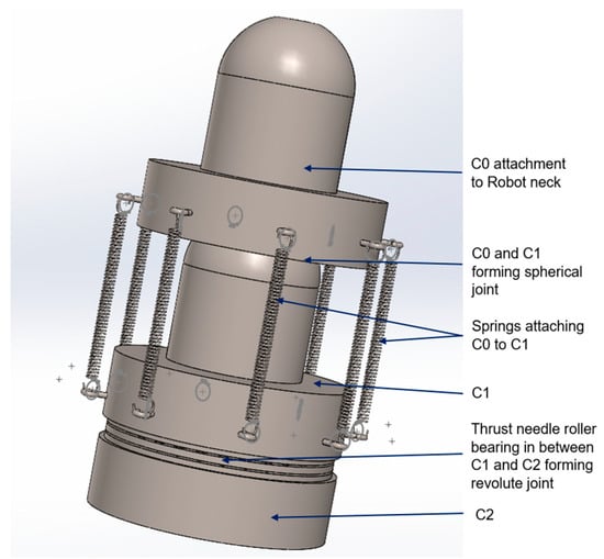
Figure 1.
A 3D model of the proposed design of a cervical vertebra for the neck of the humanoid robot, showing C0 to C2.
The nominal velocity in Table 1 represents the average velocity of human head movement, and extreme velocities occur in abnormal circumstances, such as a person turning their head very quickly after hearing an impact sound from one direction.
2.1. The Neck Design and Degrees of Freedom
The principal part of the humanoid robotic neck was designed in SOLIDWORKS (2024 - 2025 with HSM Works 2025) and manufactured (in the labs in Oxford Brookes University, Oxford, England) on a CNC lathe to ensure physical accuracy. Softwood was used on this part of the neck, which forms a semi-spherical ball joint to facilitate the three basic movements of the human head. The use of softwood helped to minimise friction during movement operations.
Figure 1 shows a 3D model of the cervical vertebrae C0, C1, and C2 for the humanoid robot’s neck. The 3D model was initially designed in SOLIDWORKS and later built from softwood. The design offers up to 4 degrees of freedom. The calculations for DOF are shown in Equations (1)–(7). One degree of freedom was found between C1 and C2, which forms a revolute joint. The other three degrees of freedom lie between C0 and C1, which form a spherical joint.
Using Grübler’s formula, we can calculate the degrees of freedom (DOFs) of the humanoid robotic neck. For general robots, the degrees of freedom can be calculated using Equation (1) below.
DOF = sum of the bodies − number of independent constraints
Equation (1) has led to Kuzbach/Grübler’s formula, shown in Equation (2) [13], which can be used to calculate the robot’s number of degrees of freedom.
whereby N is the number of Links (including the ground), J is the number of joints, m is the number of degrees of freedom (DOF) of the rigid body, fi is the number of freedoms provided by joint i, and ci is the number of constraints given by joint i [13]. Applying the standard spatial mobility Kutzbach/Grübler’s Formula (2), the humanoid robotic neck degrees of freedom can be calculated as shown in Equation (3):
As N = 4 total bodies, including base, link 1 is base (0) to C2 cervical vertebrae, link 2 is C2 to C1 cervical vertebrae, link 3 is C1 to C0 (neck attachment to the head) and the number of kinematic joints J = 3, as shown in Equations (5) and (6) below.
The DOFs of joints were distributed as one spherical joint f equal to 3, one revolute joint f equal to 1 and one fixed joint f equal to 0. This makes the expression of the sum of degrees of freedom as shown in Equation (7):
Hence, the number of degrees of freedom for the proposed humanoid robot neck is 4.
2.2. The Robotic Neck Kinematic Analysis
The kinematic behaviour of robotic systems is fundamental to achieving precise, controlled movements. The Denavit–Hartenberg (DH) convention was crucial for simplifying the representation of complex kinematic chains. Owing to its simplicity and adaptability in characterising the kinematics of robotic systems, this method has been widely implemented [14].
The robotic neck mechanism, designed to emulate the complex movements of the human cervical spine, comprises multiple joints and segments that require precise kinematic modelling. By applying the DH parameters, the kinematic chain of the robotic neck can be accurately described, facilitating the development of control algorithms that produce smooth, naturalistic movements.
As mentioned above, the robotic neck–cervical spine comprises a spherical and revolute joint. The revolute joint was given dimensions X1, Y1, and Z1 in the DH parameters diagram in Figure 2. The spherical joint was labelled into three parts based on its three main movement capabilities. This spherical joint was divided into three revolute joints, each operating at a different angle, to create pitch, roll, and yaw movement, forming three intersecting revolute axes. Yaw was given dimensions X2, Y2, and Z2. Pitch and roll was given X3, Y3, and Z3; X4, Y4, and Z4, respectively.
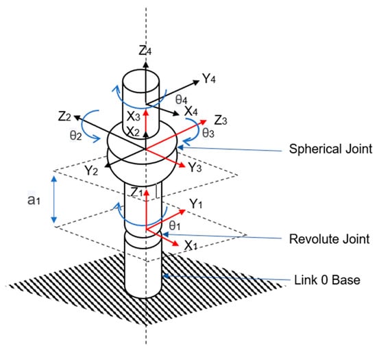
Figure 2.
A DH kinematic diagram of the proposed robotic neck.
Table 2 details the robotic neck DH parameters, which are crucial in programming robot head motion algorithms.
Table 2.
DH parameters for the robotic neck.
3. The Robotic Head and Neck Platform
The completely built robot platform, shown in Figure 3, underwent testing involving three primary neck movements: Pitch, Roll, and Yaw. This investigation was conducted following the principles of human biomechanics, wherein the cords are used to guide neck motion corresponding to the muscles responsible for analogous movements in human necks. Distinctly, the eight cords correspond to the eight human neck muscles, which are the main contributors to human head movement. Additionally, this phase encompassed integrating control systems and subsequent experimentation to refine control mechanisms.
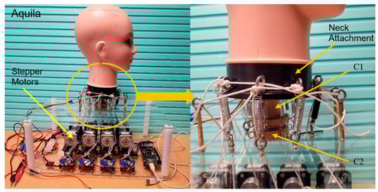
Figure 3.
The left-hand figure shows Aquila, the proposed humanoid robot platform. The figure on the right shows a close-up view of the built cervical vertebrae and the neck attachment.
The robot platform comprises two distinct sections: the bottom section, which houses eight NEMA 17 hybrid stepper motors mounted on brackets, forming a stage. The bottom part has been designed to facilitate ventilation to prevent overheating during experimentation. Each of the eight stepper motors is linked to a motor driver module (L298N), granting comprehensive control over motor operations. Electric supply cables, encompassing live and ground connections from all eight motors and their respective motor driver modules, have been consolidated into two cables for streamlined electrical supply management. Signal cables from the motors are routed to the motor drive controllers and subsequently to the Arduino Mega 2560 R3 microcontroller. This Arduino board, featuring an Atmega2560 microcontroller, boasts ample memory, 16 analogue pins, 54 digital I/O pins, and 15 PWM output pins. The Arduino board is interfaced with a computer for programming and experimentation via a USB 2.0A-to-USB Type B cable.
The upper part of the platform serves as the attachment point for the cervical spine, with driving cords threading through drilled apertures to link the motors with the Aquila robot head. These eight cords symbolise the principal muscles responsible for neck movement in humans. Between Aquila’s head and the top platform are the cervical vertebrae, including C0, where the head attachment connects to cervical vertebrae C1 and C2, which together form the typical human cervical spine, encompassing vertebrae C1 to C7. Within the robot, these cervical vertebrae are interconnected by a cable, simulating the spinal cord, which passes through the robotic vertebrae. Between C1 and C2, we installed thrust needle bearings to allow stable yaw movements. Externally, the robotic vertebrae are secured using springs that mimic the ligaments and musculature of the human cervical spine.
Figure 4 illustrates the motion configuration, showing the connection between the robot’s neck attachment and its associated motors. The platform layout specifies the precise positions of the drilled apertures and the motors.
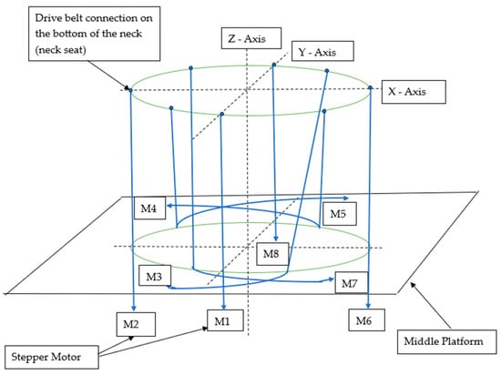
Figure 4.
A 3D graphical representation of the cord connections between the eight stepper motors and the neck attachment. The green circles represent the bottom of the neck (neck seat) and the middle platform aperture area. The blue lines show the cords connecting the bottom of the neck (neck seat) with the stepper motors.
The robot underwent numerous tests and continuous calibration procedures to ensure seamless movement, aiming to minimise jerk and bounce. Following the attainment of visually smooth movement outcomes, sensor integration commenced. Three sensor types were initially evaluated: the Time-of-Flight GY-VL53L0XV2, the Triple Axis Accelerometer ADXL335, and the MPU-6050 module, which provides 6 degrees of freedom sensing. The MPU6050 demonstrated promising results aligned with the desired data objectives.
3.1. Control and Experimentation
The main goal of a successful control mechanism is to move a robot’s head, attached to a single main neck joint, followed by another in series, to perform a desired movement similar to that of a human. From a control perspective, the humanoid robot head comprises an end effector (head), a joint (neck), amplifiers (motor drive modules), and actuators (stepper motors) for transmission and movement. This combination can be treated as an energy transformer, converting a low-power control signal into forces and torque [13]. This study utilised open-loop control to evaluate the platform’s performance in following head movement from human data. The control system implemented was to verify the functionality of the proposed motor platform’s ability to follow a predefined trajectory derived from human head movement data. This also allows evaluating the platform’s fundamental functionality to assess its capabilities and potential. The control system utilised provided a baseline for future development, including the integration of closed-loop control to improve motion accuracy further. The primary purpose is to determine if robots can replicate human movement when instructed. The phase has been crucial for diagnosing the robot’s mechanical health and actuation system, as well as for refining Arduino programming. The MPU6050 IMU sensor has been used to report robot performance, and the raw data has been crucial for optimisation. The fundamental control system of this project is displayed in Figure 5.
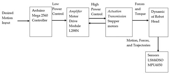
Figure 5.
A flow chart summarising the open-loop control system used to implement Aquilla’s head movement.
The Arduino Mega microcontroller controls the humanoid robotic head’s movement. Through Arduino programming, we optimised the robot’s control mechanism and altered its dynamics to achieve the desired pattern for the research stage. At this stage, we are investigating the robotic head platform’s performance to diagnose the robot’s problems and optimise its physical features before adding sophistication to achieve movement similar to that of the human head.
3.2. Methodology and Experimentation
The analysis of the robot’s movement behaviour, real-time orientation, and open-loop motion control has been implemented using the MPU6050 sensor, mounted at the centre of the robot’s head geometry. Correct positioning has enabled us to reduce noise and obtain reliable raw data. This process has also been repeated on humans to create a benchmark for investigating robot head movement. The human data sample used in this movement investigation was collected from three members of the research team. One objective of this research is to collect head movement data from 30 to 50 volunteers aged 18 to 68, and any personal details will be encrypted. The data collection process has been approved by the University Research Ethics Committee (UREC) of Oxford Brookes University. During this system-optimising phase, we used three participants from our research, as shown in Table 3. The subject 003 data was selected for the final results of this research phase.
Table 3.
A summary of the demography of the participants used to obtain human head movement data.
We incorporated the human data recorded by the research team into the Arduino code to observe head movement. Two sets of data were included as inputs. The first set of data consisted of angular velocities at different points, and the second set of data consisted of the corresponding distances moved. The time was recorded alongside the gyroscope’s output. The robot was experimentally tested at a sampling rate of 100 Hz, and the gyroscope angular velocity outputs were integrated over time to obtain angular movement around the Pitch (Gyroscope x), Roll (Gyroscope y), and Yaw (Gyroscope z) axes. Trapezoidal numerical integration was employed to estimate motion or rotation from angular velocity data by approximating the integral over time. This method converts discrete gyroscope readings into angular displacement, providing an efficient and accurate means of tracking rotational motion across applications such as robotics, navigation, and biomechanics. The movement sequence was continuous to assess the robot platform consistency. The movement starts with the roll (right to left with the pose at the starting point), followed by Pitch (starting from the rear and finishing at the front), and lastly, Yaw (starting from the left and ending on the right). A test duration of 35 s was implemented for both human data and robot data collection.
3.3. Results and Discussion
In this section, we compared the head angular movements of a humanoid robot and a human subject over a 35 s observation period. The complete angular set—pitch (X-axis), roll (Y-axis), and yaw (Z-axis)—is included, and the navigational precision, stability, and dynamic response of each system are examined.
Time series generated from MPU6050 sensor data depict elaborate angular patterns of movement across all three rotational axes over 30 s (in 35 s frames) of observation. Figure 6, Figure 7, Figure 8 and Figure 9 display results showing a correlation between human and robot data obtained from the MPU6050 sensor.
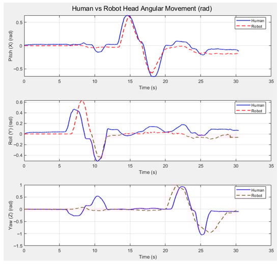
Figure 6.
Three plots comparing the angular movement (in radians) of a human head vs. the robotic head for Pitch (angular movement X), Roll (angular movement Y), and Yaw (angular movement Z).
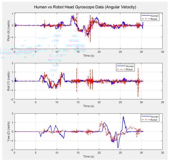
Figure 7.
Three plots comparing the angular velocity of the movement of a human head vs. the robotic head for Pitch (angular velocity X), Roll (angular velocity Y), and Yaw (angular velocity Z).
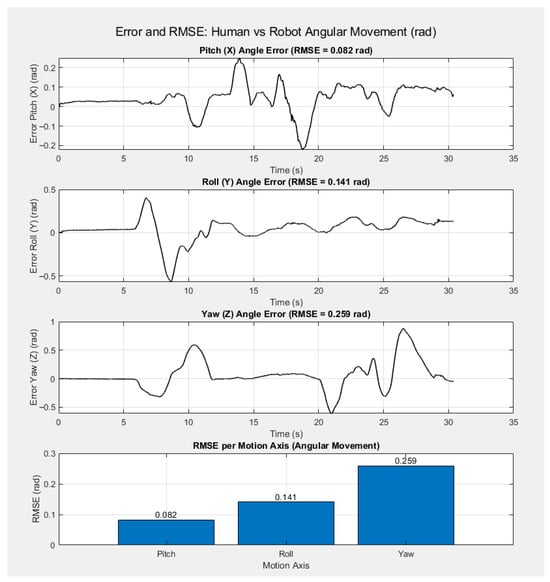
Figure 8.
Four plots showing the Error and RMSE of each angular movement (Pitch, Roll and Yaw) in rad. Note that the last plot shows the RMSE per motion axis for angular movement, displayed as a bar chart.
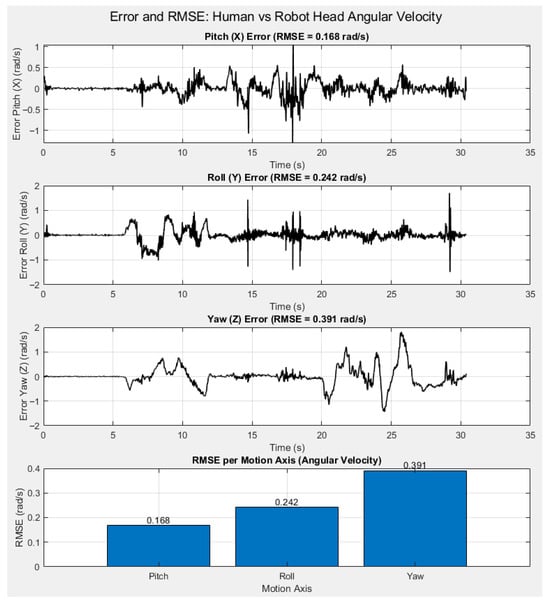
Figure 9.
Four plots showing the Error and RMSE of each angular velocity (Pitch, Roll and Yaw) in rad/s. Note that the last plot shows the RMSE per motion axis for angular velocity, displayed as a bar chart.
Figure 6 compares the angular movement of a human head with the robotic head for Pitch (Angular Movement X), Roll (Angular Movement Y), and Yaw (Angular Movement Z). We plotted the robot’s angular movements along the X, Y, and Z axes and then represented the human head’s angular movement over the same 35 s interval.
The robot’s angular distances are closer to those of humans, as shown in Figure 6. In contrast, the human plot exhibits more complex patterns, indicating naturalistic motion. The human head pitch movement exhibits a more intricate pattern with multiple peaks.
Figure 7 compares the angular velocities of human and robotic head movements for pitch, roll, and yaw. The robotic head’s pitch angular velocity shows more noise and spikes, likely due to stepper motor vibration. The trajectory of the robotic head’s pitch-forcing response is more deterministic and symmetric, likely governed by predetermined control inputs. In contrast, the human head demonstrates richer multi-phase dynamics, which are anticipated to arise, at least in part, from muscle coordination and reflexes. The pitch movement of the human head is suggested to be considerably smoother. The robotic head roll movement demonstrates smoothness but also exhibits noise. In contrast, the human head roll is likely more adaptable and perhaps less stable, requiring active stance adjustments or micro-corrections. Conversely, the robot adheres to a less varied, fixed movement pattern as programmed. The yaw movement of the human head displayed would be expected to involve smooth repositioning and scanning, rather than a more abrupt turn of the robot; this may reflect the head rotation commands the robot receives via setpoint control.
Angular velocity during human pitch movement was measured by the MPU6050 sensor (Invensense TDK Corporation, San Jose, CA 95110, USA) over 35 s intervals (from the 13th second to the 21st second). The motion was deliberately set at a low speed initially, then stepped up to the required speed before following the input speeds. This was to avoid a rapid acceleration at the beginning and to facilitate the subject’s ability to follow the pattern as instructed. Looking at the Robot’s pitch angular velocity, noise can be observed, indicating that the lower the stepper motor speed, the less smooth the movement. The pitch movement was at the 13th second and lasted until the 19th second. Human roll angular velocity during human roll movement, reflecting side-to-side head movement, started after 5 s to allow sensor calibration and stabilisation. The motion lasted for 8 s. The angular velocity of the robot during roll motion exhibits noise during periods when the robot is performing other movements. The roll movement began at the 6th second and lasted 6.5 s. The human yaw angular velocity graph indicates a minor right roll. This suggests that, during continuous changes in movement, human nature executes complex manoeuvres. The Robot Yaw angular velocity performance shows less smooth yaw movement than humans.
Figure 8 and Figure 9 show the error and RMSE of each motion axis (pitch, roll and yaw) for angular movement (Figure 8) and angular velocity (Figure 9). For the angular movement, the RMSE for pitch was 0.082 rad, for Roll (Y) it was 0.141 rad, and for Yaw (Z) it was 0.259 rad. The angular velocity RMSE pitch was 0.168 rad/s, for Roll (Y) it was 0.242 rad/s, and for Yaw (Z) it was 0.391 rad/s. The results show that the robot can follow head movement data, with an RMSE of less than 0.3 rad across all three axes. The RMSE for angular velocity is higher for each movement axis. While the results show that further improvements can further reduce the RMSE, the robotic head platform can follow the head movement data, achieving an RMSE of under 0.3 rad across all motion axes.
4. Conclusions
Our analysis reveals that the movement of the humanoid robotic head is controlled and smoother and that it demonstrates deterministic transitions. In contrast, human head dynamics, while more complex and adaptive, involve multiple oscillations and exhibit less abrupt transitions. Inter-individual variability in humans suggests greater flexibility of neural-motor systems than in robots that can replicate such a wide range yet remain unable to achieve the subtlety and adaptability of human movements.
Further refinement in sensor calibration is necessary to enhance the accuracy and precision of the obtained results. Another sensor variety to be tested is LMS6DSO. Additionally, the robot will be adapted to closed-loop control. This will enable greater positioning accuracy and facilitate self-correction. Furthermore, this research aims to test another stepper motor driver to enhance smoothness. The L298N stepper motor driver cannot operate in half-stepping or microstepping modes. During low-speed testing, although we achieved high torque, the stepper motors ran less smoothly in full-stepping mode. Introducing micro-stepping will solve this problem. The research plan involves using the DRV8825 stepper motor driver, which facilitates microstepping. Microstepping is necessary to enhance the smoothness of stepper motors [15].
Despite achieving promising results, the open-loop control system has its limitations. Open-loop control is prone to inaccuracies in precise positioning. The robotic head platform has to pair perfectly with the actuation system. The process is time-consuming, and the positioning still shows minor variation. This research has planned a feedback design to coordinate the movement control and stability of the humanoid robot head, similar to the semicircular canals of the human vestibular system [16]. Furthermore, after finalising the humanoid robot platform, we aim to implement a quaternion complementary filter to stabilise drift and smooth the motion.
Author Contributions
Conceptualization, A.A.A.-S.; methodology, A.A.A.-S.; software, A.A.A.-S.; validation, A.A.A.-S.; formal analysis, A.A.A.-S.; investigation, A.A.A.-S.; re-sources, A.A; data curation, A.A.A.-S.; writing—original draft preparation, A.A.A.-S.; writing—review and editing, N.Y., S.B., J.D. and K.H.; visualization, A.A.A.-S., N.Y., S.B., J.D. and K.H.; supervision, N.Y., S.B., J.D. and K.H.; project administration, A.A.A.-S., N.Y., S.B., J.D. and K.H. All authors have read and agreed to the published version of the manuscript.
Funding
This research received no external funding.
Data Availability Statement
The dataset presented in this article is not readily available because the dataset is part of ongoing research.
Conflicts of Interest
The authors declare no conflict of interest.
References
- Grau, A.; Indri, M.; Bello, L.L.; Sauter, T. Robots in Industry: The Past, Present, and Future of a Growing Collaboration with Humans. IEEE Ind. Electron. Mag. 2021, 15, 50–61. [Google Scholar] [CrossRef]
- Yu, J.; Li, M.; Zhang, X.; Zhang, T.; Zhou, X. A Multi-sensor Gesture Interaction System for Human-robot Cooperation. In Proceedings of the 2021 IEEE International Conference on Networking, Sensing and Control (ICNSC), Xiamen, China, 3–5 December 2021; pp. 1–6. [Google Scholar] [CrossRef]
- Peez-Zuniga, G.; Arce, D.; Alvites, M.; Cano, C.; Bustamante, M.; Horna, I.; Paredes, R.; Cuellar, F. Qhali: A Humanoid Robot for Assisting in Mental Health Treatment. Sensors 2024, 24, 1321. [Google Scholar] [CrossRef] [PubMed]
- Barker, S. The Design, Analysis and Evaluation of a Humanoid Robotic Head. Ph.D. Thesis, Oxford Brookes University, Oxford, UK, 2016. [Google Scholar] [CrossRef]
- Blanchard, A.; Mebarki, D. The Neck of Pinobo, a Low-cost Compliant Robot. In Biomimetic and Biohybrid Systems; Springer International Publishing: Cham, Switzerland, 2018; Volume 10928, pp. 40–51. [Google Scholar] [CrossRef]
- LePage, L. The Importance of Realism, Character, and Genre: How Theatre Can Support the Creation of Likeable Sociable Robots. Int. J. Soc. Robot. 2021, 13, 1427–1441. [Google Scholar] [CrossRef]
- Albers, A.; Brudniok, S.; Ottnad, J.; Sauter, C.; Sedchaicharn, K. Upper body of a new humanoid robot-the design of ARMAR III. In Proceedings of the 2006 6th IEEE-RAS International Conference on Humanoid Robots, Genova, Italy, 4–6 December 2006; pp. 308–313. [Google Scholar] [CrossRef]
- Sánchez, M.H.; Leyva, F.L.; Limón, R.C.; Zannatha, J.I. Mechanical design and kinematic analysis of the AH1N1 humanoid robot. In Proceedings of the CONIELECOMP 2011, 21st International Conference on Electrical Communications and Computers, San Andres Cholula, Mexico, 28 February–2 March 2011; pp. 177–183. [Google Scholar] [CrossRef]
- Rocha, C.R.; Tonetto, C.P.; Dias, A. A comparison between the Denavit–Hartenberg and the screw-based methods used in kinematic modeling of robot manipulators. Robot. Comput.-Integr. Manuf. 2011, 27, 723–728. [Google Scholar] [CrossRef]
- Cao, H.L.; Esteban, P.G.; Albert, D.B.; Simut, R.; Van de Perre, G.; Lefeber, D.; Vanderborght, B. A collaborative homeostatic-based behavior controller for social robots in human–robot interaction experiments. Int. J. Soc. Robot. 2017, 9, 675–690. [Google Scholar] [CrossRef]
- Fitzpatrick, R. Designing and Constructing an Animatronic Head Capable of Human Motion Programmed Using Face-Tracking Software; Worcester Polytechnic Institute: Worcester, MA, USA, 2012; Available online: https://digital.wpi.edu/downloads/8k71nh25j (accessed on 20 February 2025).
- Leigh, R.; Zee, D. The Neurology of Eye Movements; Oxford University Press: Oxford, UK, 2015. [Google Scholar]
- Lynch, K.M.; Park, F.C. Modern Robotics Mechanics, Planning, and Control; Cambridge University Press: Cambridge, UK, 2017. [Google Scholar]
- Siciliano, B.; Khatib, O. Robotics and the Handbook; Springer Handbooks: Cham, Switzerland, 2016; pp. 1–6. [Google Scholar] [CrossRef]
- Virgala, I.; Kelemen, M.; Liptak, T.; Proda, E. Stepper Motor Control by ATMELAVR Microcontroller. Appl. Mech. Mater. 2015, 816, 321–326. [Google Scholar] [CrossRef]
- Messiou, C.; Happee, R.; Papaioannou, G. Mpc-Based Postural Control: Mimicking Cns Strategies for Head-Neck Stabilization Under Eyes Closed Conditions. arXiv 2025. [Google Scholar] [CrossRef]
Disclaimer/Publisher’s Note: The statements, opinions and data contained in all publications are solely those of the individual author(s) and contributor(s) and not of MDPI and/or the editor(s). MDPI and/or the editor(s) disclaim responsibility for any injury to people or property resulting from any ideas, methods, instructions or products referred to in the content. |
© 2025 by the authors. Licensee MDPI, Basel, Switzerland. This article is an open access article distributed under the terms and conditions of the Creative Commons Attribution (CC BY) license (https://creativecommons.org/licenses/by/4.0/).