Abstract
One of the main vulnerabilities in robotic systems lies in the communication buses that enable low-level controllers to interact with the actuators responsible for the robot’s movements. In this context, hardware attacks represent a significant threat; however, the hardware version of the man-in-the-middle attack, implemented by Trojan hardware, has not yet been extensively studied. This article examines the impact of such threats on robotic control systems, focusing on vulnerabilities in an asynchronous communication bus used to transmit commands to a digital servomotor. To explore this, Trojan hardware was implemented on an FPGA device (XC7A100T, AMD: Santa Clara, CA, USA). Furthermore, the article proposes and implements detection methods to identify this type of attack, integrating them into an FPGA device as part of the actuator. The method is based on measuring the answer time detecting the presence of a strange module due to an increase in this time considering an AX-12 servomotor (Robotis: Seoul, Republic of Korea), with a Dynamixel protocol. This approach has been validated through a series of experiments involving a large number of transmitted messages, resulting in a high rate of true positives and a low rate of false negatives. The main conclusion is that response time can be used to detect foreign modules in the system, even if the module is kept waiting to attack, as long as the condition that the servomotors have a low variation in their latency is met.
1. Introduction
Today, robotic platforms are widely used in a variety of everyday operations, including applications where safety is a critical factor. In this context, robot vulnerabilities are beginning to attract significant attention from attackers [1,2,3], since numerous attacks on robotic platforms have been reported [4,5,6]. Consequently, the development of cyber-secure robots has become increasingly important.
Despite the above, many robot manufacturers often fail to include safety considerations in their design cycles. Instead, security is considered an external factor outside the system.
However, this trend is changing. In the academic domain, interest in cybersecurity for robotic platforms has grown drastically, as shown in Figure 1. Data for this study were obtained from Google Scholar, using the search strings “cybersecurity”, “robotics”, and “platform”. However, while most of the publications address the need to defend robotic platforms against particular threats, they seldom approach specific defense techniques against concrete attacks. The inclusion of the term “countermeasures” in the search query decreases the number of publications, as can be seen in Figure 1 (blocks filled). Therefore, these data justify the need for continued research on defense mechanisms in the field of robotics.
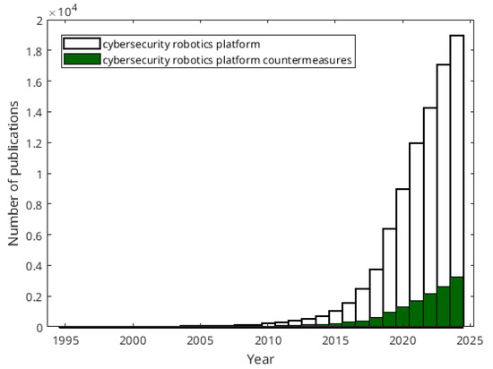
Figure 1.
Number of publications about the subject of secure robotic platforms.
Beyond the academic domain, an increasing number of organizations are warning of the need to incorporate security within the design stages. An example of these organizations is the Instituto Nacional de Ciberseguridad (INCIBE) in Spain. In addition, there is a standard on industrial cybersecurity—ISA/IEC 62443 [7]—which establishes specific requirements to preserve the security of industrial systems. According to this standard, there are seven basic requirements that must be taken into account:
- Identification and authentication control.
- User control.
- System integrity.
- Data confidentiality.
- Restricted data flow.
- Timely response to events.
- Resource availability.
These requirements will reduce many risks in any industrial robotic system. According to these requisites, cyber protection can be classified into four levels:
- Level 1. Protection against casual or coincidental violation.
- Level 2. Protection against intentional violation using simple means.
- Level 3. Protection against intentional violation using sophisticated means.
- Level 4. Protection against intentional violation using sophisticated means with extensive resources. This level involves defending against resource-intensive attacks from organized crime or government agencies.
When considering security measures for robotic systems, they should be designed to meet levels three or four, as the use of sophisticated methods is more prevalent in this technological field. Specifically, the techniques proposed in this work aim to enhance the security level of standard implementations.
The functionality of robotic platforms relies on a communication process between a main controller, which makes decisions regarding the robot’s movements, and low-level controllers, which convert motion references into actuator commands. In addition, there are other communication processes that the low-level controller establishes with sensors and actuators. This work aims to explore the effects of certain vulnerabilities in asynchronous buses that support communication between actuators and low-level controllers. Special attention is paid to the man-in-the-middle attack modality, in which a malicious actor, placed within the communication channel, covertly intercepts and potentially alters the data exchanged between two interlocutors [8].
In particular, this article presents a study aimed at demonstrating the real threat that hardware implementations of man-in-the-middle attacks pose to robotic platforms, and at establishing a methodology to detect the potential presence of an attack module designed to modify robot task execution by altering communications between the low-level controller and the actuators. Although the verification of this approach has been carried out in an initial simulation phase, all the results shown in this work have been obtained through experimental validation. To this end, experimentation and testing have been carried out using a commercial motor to verify the proposed methodology, since an attack on a single actuator can completely compromise the effective operation of the entire robot.
A secure system design flow should include the specifications necessary to avoid the effects of potential attacks, as well as the correct behavior if an attack is detected. These tasks are accomplished through the following steps:
- Identifying the behavior of the system.
- Generating the attack models.
- Establishing an adequate security policy.
- Implementing the security mechanism in accordance to the established policy.
The attack model will include the vulnerabilities the attacker will exploit and also the method to take advantage of them. However, it should be noted that the work focuses on the defense strategy, and not on how the attacker manages to incorporate his module into the system.
The security policy will analyze the vulnerabilities and the possible implementation of the attack. From this analysis, the system behavior must include specifications to reduce vulnerabilities and/or detect possible attack. Finally, these specifications must be implemented.
The organization of this paper is as follows. Firstly, the context of the study will be presented. Next, the attack model defined in this approach will be detailed. The defense strategy and its results will be discussed later. Finally, the main conclusions and future works will be presented.
2. Case Study: A Robotic Actuator Based on the Dynamixel Protocol
The primary function of an actuator on a robotic platform is to enable movement. In the case of mobile robots, this movement involves displacement through a path. Meanwhile, in the case of a manipulator, this movement involves the modification of the position of each link. Basically, two kinds of actuator can be distinguished: continuous motors and servomotors. Continuous motors are limited to rolling continuous movements, which makes them more suitable for applications requiring uninterrupted motion. In contrast, servomotors can rotate to a specific angle, making them ideal for tasks that require precision and the use of a position controller. Among servomotors, digital versions stand out as they incorporate a digital controller capable of facilitating communication, providing feedback on the control process, and interpreting commands.
One of the most widely used servomotor families in the field of robotics is the Dynamixel series. These servomotors are employed in a wide range of applications. For instance, in the industrial domain, Dynamixel AX-12 servomotors have been used in the implementation of manipulators [9]. In the space domain, these servomotors have been employed to implement grippers for berthing tasks [10]. In the aerial robotics field, they have been used to control the center of mass of aerial vehicles [11].
To conduct this study, a multi-articulated robotic platform was considered, featuring up to 24 digitally controlled motors operating in a coordinated manner (see Figure 2). This platform is a hybrid robotic hexapod capable of moving using six legs or the wheels attached to each leg [12]. Hybrid hexapods have received special attention in recent years due to their exceptional versatility in adapting their traction mode based on the terrain they operate in [13,14,15]. From the perspective of this study, the hybrid hexapod serves as an ideal platform, as it effectively demonstrates the impact of the proposed attack model.
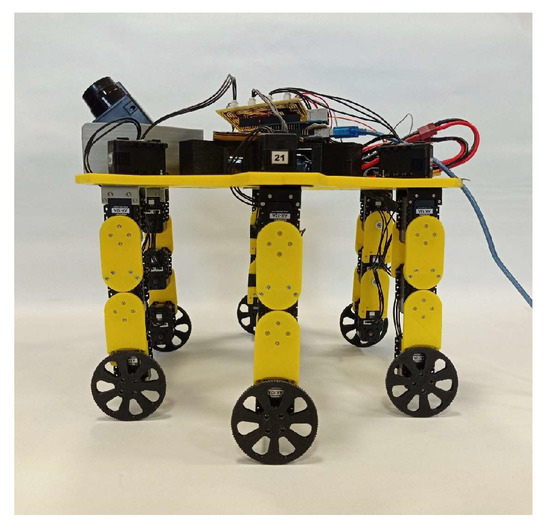
Figure 2.
Experimental platform: the hybrid hexapod.
In this work, the communication between the low-level controller and the actuators will be implemented in compliance with the following specifications:
- Using actuators from the Dynamixel family.
- Transmitting commands from a Personal Computer (PC) through a UART connection.
- Sending simple pre-stored commands from a selection.
- Sending complex pre-stored commands from a selection, such as a sequence of orders corresponding to a step.
2.1. Communication Protocol Description
Digital servomotors typically utilize communication protocols to provide feedback to the control process and receive commands from low-level controllers. This article focuses on the Dynamixel asynchronous protocol [16] and approaches the vulnerabilities associated with the digital servomotors of Dynamixel; particularly, experiments have been implemented with the model AX-12A. Since all Dynamixel actuators employ the same communication protocol, the findings of this study are applicable to all actuators produced by this manufacturer. Moreover, this analysis and the identified vulnerabilities can be extended to any other asynchronous transmission protocol used for communication with robotic actuators. The Dinamixel protocol scheme is shown in Figure 3, using version 1.0. It is based on the transmission of two packets: instruction and status packets. The instruction packet consists of six or more bytes: two for synchronization, the address of the slave to communicate with, the packet length (in number of bytes), the instruction to be executed, and a checksum byte to detect errors in transmission. These packets are sent by the communication master (the low-level controller shown in Figure 4).
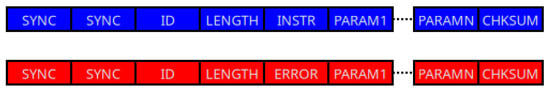
Figure 3.
Format of Dynamixel protocol: instruction package (marked in blue), and status package (marked in red).
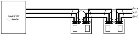
Figure 4.
Architecture of the communication process.
The format of the status packet is identical to that of the instruction packet. The only difference is that the instruction byte (INSTR in Figure 3) is replaced by an error byte (ERROR in Figure 3). This byte provides information on the execution of the instruction sent by the controller, and therefore, the packet is sent by the slave (the actuators shown in Figure 4) to the controller.
The transmission of the packet is performed using a half-duplex UART protocol. This communication method allows data to be sent and received over the same wire, enabling multiple blocks to share the connection. To achieve this, each block must release the bus after use, leaving the wire in a high-impedance state.
2.2. Physical Implementation
Communication using the Dynamixel protocol can be implemented in several ways. One approach is to use the USB2Dynamixel device, which connects the servomotors directly to a computer via a USB interface [17]. Another option is to use an Arduino-based platform, as many libraries have already been developed to control these servomotors.
Vulnerability analysis and solution prototyping require complete control over message structure in different aspects. First, low-level control at the logical level is essential for monitoring individual bytes within the message structure. Furthermore, precise control over the timing of these bytes is crucial, as time measurements will be used as a defense strategy. These restrictions imply a concurrent or parallel mode of operation, as precise synchronization between the received message and the time measurement is required.
Consequently, the USB2Dynamixel device is rejected for vulnerability analysis as it is a closed solution that prevents access to the interior of the packages. Similarly, a microcontroller-based solution is discarded because its natural mode of operation is not concurrent, and any methodology to implement concurrent operations within a microcontroller-based architecture lacks sufficient precision for accurate synchronization.
Thus, as a hardware solution for system implementation, an FPGA-based development was selected for the following reasons: first, it enables direct implementation of the package and provides full control over the hardware logical structure; second, this platform supports parallel operation and allows for more precise timing measurements. A summary of this discussion is presented in Table 1.

Table 1.
Summary of implementation methods.
The development board used in the study is the Arty7 board [18]. This board utilizes an Artix7 family FPGA device [19], which is cataloged as a low-cost FPGA with limited resources. In particular, the device used is a XC7A100T whose characteristics are shown in Table 2.
Table 2.
Hardware resources of FPGA device.
The operating conditions in the transmission have been chosen in such a way that they represent the most restrictive situation allowed by the communication protocol (baud rate of 1 Mbaud), choosing an operating frequency for the FPGA of 100 Mhz that minimizes the error range at that transmission speed.
In this sense, Figure 5a illustrates the architecture of a master block for the Dynamixel protocol implemented on an FPGA. This block comprises a data input module that determines the commands to be transmitted (which may vary according to the application), a FIFO memory for temporary storage of command bytes, a module implementing the Dynamixel protocol to handle protocol-specific operations, and a half-duplex UART interface responsible for transmitting the command bytes.
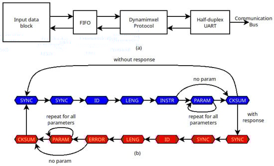
Figure 5.
(a) Architecture of the FPGA implementation, and (b) behavior of Dynamixel protocol: instruction package (marked in blue), and status package (marked in red).
The behavior of the Dynamixel protocol block is illustrated in Figure 5b. First, the master waits until a command needs to be sent. Then it generates the bytes associated with the corresponding command (highlighted in blue) and transmits them to the half-duplex UART. Once the command is sent, if the ID byte corresponds to the broadcast address, no slave will respond, and the master will return to the standby state until a new command needs to be sent. Otherwise, the master waits to receive the status packet from the selected slave (highlighted in red). Once the response is received, it is passed to the input data block for processing. Finally, the protocol module evolves to the standby state to send the next command.
In Figure 6, the behavior of the master block implementation is analyzed using a logic analyzer, more concretely Analog Discovery 2 [20]. The waveform labeled “bus” represents the data flowing through the bus, while the other waveforms correspond to the states of the Dynamixel protocol. In this example, the transmitted command orders the servomotor to turn on the LED (all servomotors are provided with an LED for testing purposes), as shown in the blue packet. The dark blue waveform illustrates the different stages of the protocol during the transmission of the instruction packet. Following this, there is a time interval until the slave responds to the command. In this case, the response indicates that there are no errors, as shown in the green packet. The dark green waveform shows the different stages of the protocol during the reception of the status packet.
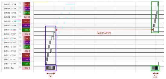
Figure 6.
Behavior of the Dynamixel controller using a logic analyzer.
Furthermore, three timing intervals can be identified: first, the time required to transmit the instruction packet, labeled ; second, the time it takes for the actuator to prepare its response, labeled answer; and third, the time required to transmit the status packet, labeled .
The hardware resources from the controller implementation are shown in Table 3. It is important to note that the controller is a small system, and a low-level device can be used, or several controllers can be implemented in the same device, allowing decentralized control.
Table 3.
Hardware resources of the main controller. Percentage of use is based on data in Table 2.
3. Attack Model
3.1. Vulnerabilities of the Dynamixel Protocol
The first stage in developing the attack model is to identify the vulnerabilities that the attacker may exploit. In this work, two specific vulnerabilities are considered: the use of a public protocol without encryption and the connection of the actuators in an expandable daisy chain. These weaknesses make it straightforward to insert a new attack module into the chain, enabling communication with the master and slave modules while replacing their identities.
3.2. Hardware Attack
Traditionally, scientific literature has focused on the study of software attacks, which involve embedding malware within the system’s software architecture. However, there are other types of attack that do not require any software component to be executed. This is the case of attacks aimed at altering the physical components of the system and are commonly referred to as hardware attacks [21]. They can be classified into three groups:
- Physical attacks [22]. These attacks modify the system to attack.
- Side channel attacks [23]. These attacks use secondary characteristics to obtain information from the system. Some examples of these characteristics are latency, power consumption, electromagnetic radiation, etc.
- Faults injection attacks [24]. These attacks cause a system fault to gain information. Some examples of these faults are the use of an operation frequency different from the correct one, the use of a polarization voltage lower than the correct one, etc.
This work is devoted to exploring the effect, detection, and possible avoidance of a hardware implementation of the man-in-the-middle attack [25] on a robotic platform. The man-in-the-middle attack is a conceptual threat that, depending on its implementation, can fall into a different of the aforementioned categories. Most cases are classified as physical attacks because their effectiveness often requires modifications to the system hardware. When an attack module is integrated into the system, it is referred to as Trojan hardware [26]. The purpose of this type of module is to create a backdoor that enables unauthorized access to the transmission of critical information. The primary functionality of a man-in-the-middle attack is to monitor the communication channel to alter, modify, or capture that communication, including commands and information.
The inclusion of a Trojan hardware in the system can be done by three potential actors:
- An unreliable manufacturer in the design and/or fabrication processes.
- An unhappy worker of a trusted manufacturer in the design and/or fabrication processes.
- An external agent during the life cycle of the system.
In the case of a malicious manufacturer, the traditional solution is to work only with trusted manufacturers. In the case of an unhappy worker, the manufacturer must test whether the layout has the same elements as the schematic (for example, with tools such as LVS, Layout Versus Schematic). In this paper only the third case is considered, since the two first must be addressed during the design and/or manufacturing processes and are therefore the responsibility of the manufacturers. Consequently, this study focuses on attacks that originate from an external device, which could be covertly integrated into the system.
3.3. Strategy of Man in the Middle Attack
The implementation of the man-in-the-middle attack involves inserting an attack module into the communication bus. This module is placed between the controller and the chain of actuators, as shown in Figure 7. In doing so, the module can isolate the controller and replace the instruction packets.
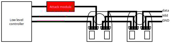
Figure 7.
Architecture of the scenario to be attacked including the attack module.
The architecture of the attack module is shown in Figure 8. This module consists of three different blocks. First, there is a block responsible for establishing communication with the low-level controller (similar to the one shown in Figure 5b). Second, a block determines the type of attack to be executed. Finally, another block establishes communication with the actuator chain (also similar to the one shown in Figure 5b).
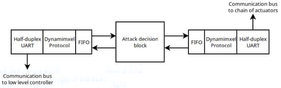
Figure 8.
Scheme of the attack module to level block.
When a robot is threatened, the most common objective of attackers is to alter its intended movement. In this article, attacks are carried out by modifying instructions related to rolling and/or positioning. To achieve this, the attack decision block analyzes the commands sent by the low-level controller and determines the actions to execute. These actions can be programmed as follows:
- Do Nothing. It will transmit the order from the controller to the actuator chain and then it will transmit the status from the actuator to the controller. This action can be classified as a replay attack, in which the packet is captured for later use. However, in our case, the goal of this situation is to hide the attack module.
- No order is transmitted. It will not transmit the order from the controller, and then it will transmit a correct status package to the controller in order to avoid detection of the attack. This action can be classified as a denial of service (DoS) attack, in which the system takes no action (because it does not receive any commands).
- Changing the parameters of orders of rolling or positioning. If the block detects one of such orders, the parameter fields will be changed, and then it will transmit a correct status package to the controller in order to avoid detection of the attack. Otherwise, it will have the same behavior as in the first case. This action can be classified as stealthy packet manipulation, in which the attack module modifies the content of communication.
The behavior implementation requires the packet analysis. Therefore, the decision about the attack must wait until the transmission is completed.
The behavior of the attack module is illustrated in Figure 9, showing two different scenarios. In Figure 9a, the attack module is programmed to maintain the instruction packet from the controller without modification, that is, no attack is executed, and the presence of the attack module remains transparent. In this figure, first, the attack module receives the instruction packet from the controller, places it on the communication bus, and then waits for the actuator response. Finally, once the response is received, the attack module forwards it to the controller.
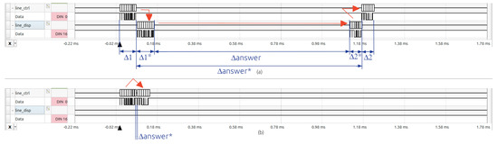
Figure 9.
Behavior of the attack module. (a) Not attacking situation, and (b) attack without sending any instruction to actuator.
In Figure 9b, the attack module is programmed to prevent transmission of the controller instruction to the actuator. Additionally, the attack module sends a status packet to the controller, causing the controller to believe that the communication process has been completed. In this figure, the module first receives the instruction packet from the controller, and then the attack module returns a status packet to complete the communication protocol according to the programmed attack. The attack module can include a delay before sending the status packet.
The case of changing a parameter in the instruction packet is similar to the first case (Figure 9a) because the only variation is the change in the value of a single byte, while the overall structure and the total number of bytes in the communication remain unchanged.
The hardware resources corresponding to the implementation of the attack module are shown in Table 4. It is important to note that the attack module has two controllers in addition to the decision block (shown in Figure 8). Therefore, the attack module always requires more hardware resources than a single controller (whose hardware resources are shown in Table 3).
Table 4.
Hardware resources of the attack module. Percentage of use is based on data in Table 2.
Finally, it is important to note that although the attack module presented in this work was developed on an FPGA, an attacker could implement it using custom hardware specifically designed to replicate the functionality of the proposed architecture, while also featuring the miniaturization required to conceal an act of sabotage.
4. Security Policy
Firstly, it is important to note that the vulnerabilities approached by the attacker cannot be removed from the current actuator configuration by the following reasons:
- A public protocol allows for greater use of these actuators. In principle, communication could be encrypted; however, current actuators do not support this functionality.
- An expandable chain permits these actuators to be used in a large number of applications.
Therefore, the defense strategy cannot be aimed at directly eliminating these vulnerabilities, but rather at minimizing the advantages that the attacker can take from them.
In the case of the man-in-the-middle attack, the main defense strategies found in literature can be divided into two categories:
- Strategies oriented to defense the message.
- Strategies oriented to defense the communication channel.
In the first category, the defense involves ensuring that the receiver can identify whether the message is sent by an unauthorized block. In this sense, the traditional defenses are the following:
- Encrypting messages to make them harder to understand.
- Adding different marks to messages to make them unique.
In both cases, the actuators must be prepared to decrypt or analyze the content of the message. In our study, these commercial actuators do not support these functionalities and, therefore, such solutions have been discarded.
In the second category, the defense involves detecting the presence of a strange block (Trojan hardware) in the communication channel. Traditionally, this defense involves inspecting the system to identify and remove unauthorized components. Depending on the application, the frequency of performing these inspections will be very different. Therefore, it would be useful to have a tool capable of detecting the potential connection of malicious modules that will recommend when inspections are required.
4.1. Related Work
Several approaches have addressed the problem of detecting Trojan hardware connected to electronic circuits. In ref. [27], the trust evaluation of a robotic platform is surveyed. In the case of hardware level, trust involves the identification of extra hardware that can be considered as Trojan hardware. In this case, detection is performed by inspecting several measurements: logical equivalence, signal activity rate, structural architecture, functional correctness, and power consumption.
Detecting a deviation from the reference value during these measurements indicates the possible presence of a hardware Trojan. However, these solutions are typically applied to integrated circuits, as such measurements are difficult to obtain on a printed circuit board because the actuators’ operation can mask deviations caused by the Trojan hardware.
In ref. [6], the presence of the Trojan hardware is detected through the anomalies introduced in data bus by the attack module. The anomaly consists of altering the frequency of the SCL signal.
In ref. [28], a multi-parameter metric is used to detect the presence of the attacker module. These parameters are power consumption, timing variation, and leakage current. The detection process consists of comparing the metric with a threshold value.
In ref. [29], strain sensors measure the bending or stretching of the wires. The inclusion of a Trojan hardware can modify these measurements and, hence, the presence of the intrusive hardware can be detected. However, this assumption requires the wires to have low variation strain. In our case, no assumption about the platform structure is considered and, therefore, this solution is not applicable.
Also, machine learning techniques are used to detect the presence of a man-in-the-middle attack. In this case, two different types of feature are present in the learning process. Firstly, some parameters of the transmission process are used in training.
In ref. [30], some characteristics of Ethernet communication are used to detect anomalies in the communication process. Some examples of these characteristics are the timestamp and IP address.
Moreover, the value of specific sensors is used in training. In ref. [31], this type of feature is used to train the anomaly detection algorithm. The variation in characteristics is assumed to be low.
In both cases, it is worth noting that the detection is produced when the attack is executed, which can be dangerous, since the attacking module could be waiting to carry out attacks without being detected.
In the case of other communication protocols, solutions are usually tailored to their specific characteristics. Therefore, their use in the Dynamixel protocol is either not applicable or has very limited application.
For example, the authors of [32,33] indicate that the main vulnerabilities of the CAN bus are the lack of information about the sender and receiver addresses (in a broadcast communication) and the lack of message authentication mechanisms. To try to reduce the exploitation of these vulnerabilities, different defense mechanisms have been used, such as message encryption, analyzing the information received at the gateway, including hardware firewalls based on configurable rules (signatures), or analyzing the time between communications from the same actor (since they always send messages regularly).
In ref. [34], the detection of Trojan hardware in the I2C protocol is analyzed. In this case, the assumption is made that such hardware will increase the amount of traffic on the communication bus. Therefore, the solution is based on analyzing this traffic using different characteristics: time between successive frames, frame duration, number of bytes exchanged, number of frames, and number of ACK and NACK bits.
4.2. Proposed Defense Strategy
After analyzing the behavior of the attack module, the primary effect of its presence is a change in response time compared to unaltered transmission. For example, when a command passes through the attack module, the time required to analyze the packet is added to the transmission time of the command packet and the actuator response packet. This fact can be observed from the analysis of Figure 6 and Figure 9a), where the following parameters can be identified:
- represents the time required by the attack module to generate the instruction packet, which is similar to 1 since both implementations are identical (shown in Figure 9). This time should also include the attack module’s decision time. However, this time is considered negligible compared to the packet generation time.
- answer* is the elapsed time between the completion of the controller’s transmission of the instruction packet and the reception of the actuator’s response, in the presence of the attack module (shown in Figure 9).
- represents the time required by the attack module to to generate the status packet, which is similar to 2 since both implementations are identical (shown in Figure 9).
As shown in Figure 9a, when the attack module is present, includes the value of and the delay caused by the operation of the attack module, as defined in Equation (1).
Figure 9b shows the behavior when the attack action consists of preventing the instruction from being transmitted to the actuator. In this case, the response time will be lower than usual, even similar if the module tries to replicate it. However, Equation (1) is fulfilled most of the time, since the attack module must wait for the actuator’s response in most transmissions.
From these facts, it is evident that the response time recorded in the presence of an attack module () shows variations compared to the response times measured when the system was in its original state. If is appropriately characterized, it may be possible to establish criteria to compare the recorded response time with the characteristic time, thereby determining whether an attack module is connected to the system.
To enable this detection, the authors hypothesize that the delay between the transmission of an instruction and the reception of the status packet, when no attack module is present (), should be consistent and accurately predictable. Therefore, any significant deviation in the response time would indicate the presence of an external element between the controller and the actuator. To characterize this consistency, the range of values of is identified by determining its minimum () and maximum () values. Based on this range, the following hypothesis is formulated:
Hypothesis 1.
Proof.
The minimum response time in the presence of an attack module is given by:
From the initial hypothesis condition, it follows that:
Therefore:
which holds for all values of , confirming the hypothesis regarding attack detection. □
However, this hypothesis must first be experimentally validated. Figure 10 illustrates three different behaviors of the actuator response, highlighting the instruction packet in blue and the status packet in green. The upper waveform shows normal transmission, which is typical in most cases. In this case, the time necessary to prepare the status packet is marked between two red lines that will be taken as reference in the other cases. The middle waveform illustrates a faster response from the actuator. However, these responses have a delay inside the status packet. Finally, the lower waveform shows a slower response. Thus, the response time of the actuators exhibits some variability, and it is necessary to determine whether this variability permits applying the proposed hypothesis for detecting the attack module.
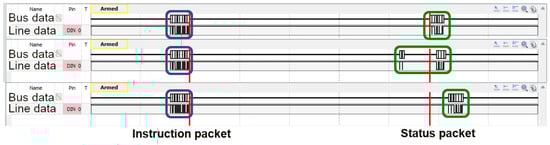
Figure 10.
Different behaviors in the answer of the actuator.
In order to test the usability of the response time as a detection mechanism, a sequence of eight instructions was sent. This sequence consisted of the following commands: turn on the actuator LED, send a ping instruction, turn off the LED, send another ping instruction, position the actuator at 0°, send a ping instruction, position the actuator at −75°, and finally send a ping instruction. This sequence was repeated 110 times, as it is considered representative of all possible behaviors. For that, the time has been measured for 880 instructions (corresponding to 110 sequences) without the attack module (answer). This procedure has been repeated with the attack module (answer*). These instructions have been chosen because they are among the most commonly used, as well as being the most suitable for altering the functionality of the actuator. In fact, motion instructions are specifically employed to provide functionality to the actuator. Ping instructions, on the other hand, are commonly used by controllers to verify the active listening state of actuators that, due to the nature of the operation, remain inactive for a period of time. Finally, LED instructions are used to convey information about the system’s operational status for maintenance purposes. For all these reasons, these instructions are of interest to potential attackers, since its manipulation would affect task execution effectiveness, the information regarding the actuators’ active state, and the data provided by the controller for maintenance- related purposes.
In Figure 11, this delay is shown for the transmission of 880 instructions (110 “Led On” instructions, 110 “Led Off” instructions, 110 “Move 0°” instructions, 110 “Move 75°” instructions and 440 “Ping” instructions shared in four plots). Each graph represents the results of a study conducted for a specific type of instruction. In the case of the blue lines, the attack module is not present, as illustrated in Figure 4, and the measurement will be answer. Meanwhile, in the case of the red lines, the attack module is included in the system, as shown in Figure 7, and the measurement will be answer*. In addition, the black lines represent the maximum amplitude reached by the blue lines (the difference between the maximum and minimum answer). These results clearly indicate a significant difference between the blue and red lines, validating the hypothesis proposed by the authors, suggesting that this characteristic can be used to detect the presence of the attack module.
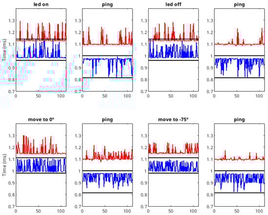
Figure 11.
Delay between instruction and status packets without the presence of the attack module (blue line) and with the presence of the attack module (red line). The black lines mark the range of blue waves.
Next, we present the analysis of the different instructions. In the case of the LED commands, the blue line crosses the red lines, indicating that these instructions cannot be used for complete detection, that is, the Equation (2) is not fulfilled. In the case of using this instruction in the detection process, a certain degree of false rejection must be assumed.
In Figure 12, the authors show a statistical analysis of the data included in the hypothesis verification process. The data have been divided into the three types of instructions considered: led, ping, and move instructions. The analysis consists of a box plot that includes the mean value and the standard deviation. From it, the deviation for all instructions is lower than 5%. From the box plot, we can see that the variation is low (practically all data from the ping and move instructions are inside the box). In the case of the move instruction, the data dispersion is greater, since more data are visible outside the box. However, this dispersion is not very large, less than 0.2 ms.
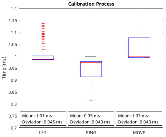
Figure 12.
Statistical analysis of data to verify the hypothesis presented.
Considering the ping instructions, no blue line crosses the red lines—that is, Equation (2) is fulfilled—indicating that, for this instruction, the response time criterion can be used to detect the presence of the attack module. In these cases, a decrease in delay is notable in several instances of the blue lines (when the attack module is not present). However, in the red lines (when the attack module is present), there is an increase in delay. This is due to the faster response of the actuator, as shown in Figure 13. In this case, the higher value of (due to the faster response) accounts for the difference between the two behaviors.
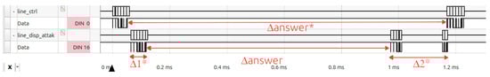
Figure 13.
Behavior of the communication channel when a faster response is produced.
With respect to move instructions, the blue lines do not cross the red lines; that is, Equation (2) is fulfilled. Therefore, for these commands, the response time criterion can also be applied to detect the presence of the attack module.
These experiments demonstrate that the response time for certain commands is sufficiently consistent to be used for detecting attack modules in the communication channel. This consistency depends solely on the communication between the electronic systems of the low-level controller and the actuator, and is unaffected by other factors arising from the robot’s mechanical behavior or other electronic components that might interfere with the control loop.
5. Security Mechanism
The security mechanism will be implemented within the system itself to allow detection throughout its entire operational life. This constraint involves hardware implementation. Due to this fact, learning algorithms were discarded due to their high computational and hardware resource demands. Instead, a simple threshold-based algorithm was used, producing very satisfactory detection rates, as shown in Figure 11.
Once the hypothesis has been verified, a defense strategy is proposed. In this approach, the defense is activated for instructions that guarantee the detection of the attack module, specifically the ping and moving instructions. Figure 14a illustrates the proposed architecture for implementing a low-level controller with the defense strategy. As shown in this figure, a defense module connected to the Dynamixel controller has been added to identify the executed instruction and monitor the actuator’s response. If the module detects response times that are higher or lower than expected, it will trigger an alarm, allowing an operator to inspect the system and verify the possible presence of an attack module.
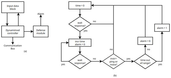
Figure 14.
(a) Architecture of the implementation of the low level controller including the defense strategy. (b) Behavior of the defense module.
The behavior of the defense module is described by the flow chart shown in Figure 14b. First, the module reads the instruction to be executed and starts a timer. Once the instruction packet is sent, the timer is activated to measure the time until the actuator’s response is received, measuring answer (if no attack module is present) or answer* (if the attack module is present). If the instruction requires activation of the defense module, the measured delay is compared with a pre-defined acceptable range. If the delay falls outside this range, the alarm is triggered.
The implementation of this defense strategy requires a configuration process to determine the correct delay range. This configuration must be carried out in the absence of the attack module and consists in measuring the response delays (answer in Figure 6) of the servomotors. The valid range is defined as the maximum range obtained during this configuration process. Table 5 presents this range for each instruction.
Table 5.
Timing values corresponding to the transmissions of several orders. answer corresponds to the time shown in Figure 6.
Next, we present a study on the detection of the attack module. In Figure 11, it can be seen that the authors’ hypothesis consistently characterizes the presence of the attack module. To test detection mechanism, the authors evaluated the approach by conducting a new set of experiments with an increased number of samples. Specifically, we considered 500 sequences of instructions without the attack module and 500 sequences of instructions with the attack module, comprising 2000 LED instructions, 2000 Move instructions and 4000 Ping instructions.
Next, we present a study on attack module detection using the authors’ hypothesis, characterized in Figure 11. To test the detection mechanism, we used 2000 LED instructions (1000 without an attack module and 1000 with an attack module), 2000 Move instructions (1000 without an attack module and 1000 with an attack module), and 4000 Ping instructions (2000 without an attack module and 2000 with an attack module). To increase the randomness of the behavior, the instructions were grouped into sequences of eight instructions, mixing the different types. All instructions were tested in 500 sequences (4000 instructions in total) without an attack module and in 500 sequences (4000 instructions in total) with an attack module. The results are shown in Table 6. For all the instructions considered, when the attack module is present in the system, the detection is absolute, with a true positive rate of 100% and a false negative rate of 0%. In contrast, when the attack module is absent, there is a minimal probability of a false positive in the Move and Ping instructions, which confirms the results shown in Figure 11. Therefore, the instructions selected for the defense procedure are those with the lowest false positive probability, namely the Move and Ping instructions.
Table 6.
Timing values corresponding to the transmissions of several orders. , and correspond to the times shown in Figure 6.
Once the defense module was integrated into the system, its correct functionality was tested using a logic analyzer. The tests were conducted under normal operating conditions, so significant variations in environmental and/or external parameters are not expected. Therefore, the pre-configuration process should maintain the correct values, as minor variations are expected to fall within the operating ranges of the different system components included in their datasheets [16,19].
The resulting waveforms are shown in Figure 15. In these tests, the same sequence of instructions was used, including the LED, move, and ping commands. The figure illustrates the controller communication channel (line_ctrl signal), the attack communication channel (line_attack_disp signal), and the detection of an attack (attack signal). In Figure 15a, the actuator is connected to the line_ctrl signal, and therefore the operation of the attack module does not have any effect on it. In this case, no attack is detected since no additional delay exists.
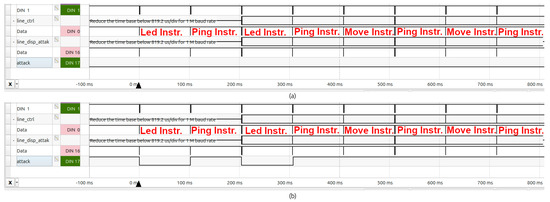
Figure 15.
Behavior of the system including the defense module (a) without the attack module and (b) with the attack module.
On the other hand, in the experiments corresponding to Figure 15b, the actuator was connected to the line_disp_attack signal, and thus the operation of the attack module affected it. Since the defense module was designed to activate when a ping or move instruction is executed, the attack is detected whenever a ping or move command is sent, due to the additional delay introduced by the operation of the attack module.
The hardware resources corresponding to the implementation of the defense module are shown in Table 7.
Table 7.
Hardware resources of the defense module. Percentage of use is based on data in Table 2.
It is worth noting that the study was conducted when the attack module was in a transparent state, meaning that the communication process was not altered (the most common action of the attack module). Therefore, the attack module will be detected when included in the system, even if it does not cause any modification to the transmitted messages.
6. Conclusions
In this article, we analyze the vulnerability of a robotic platform to a man-in-the-middle attack. This analysis was conducted exclusively at the hardware level. In conclusion, it is worth highlighting, first, that it is not difficult to intrude improper circuits on open platforms, as they are prepared to be changed or to include new modules. Second, when the actuator response time exhibits low variability, response time measurements can be used to detect the inclusion of a module external to the platform, as the attacking module requires analysis time to decide its action.
More particularly, the analysis has considered an architecture compounded by a low-level controller (master module) connected to a chain of actuators (slave modules), which is a typical architecture. The Dynamixel protocol has been used to communicate the master and slave modules, which are AX-12 servomotors. However, this study is perfectly valid for any engine that uses the protocol considered, including all engines in the Dynamixel family.
An attack module has been inserted between the low-level controller and the actuator chain. This module has three operating modes: do nothing, transmit no command, and modify some parameter of the transmitted command. Analysis has shown that the attack module can modify or terminate communication without the low-level controller detecting this situation.
Once the possibility of the attack has been characterized, an analysis of the attack effect is necessary to find a possible countermeasure. The main effect is the increase in response time due to the operations performed by the attack module, including analysis and decisions.
Previously, to find a countermeasure based on response time, it was necessary to show that the actuator response time has a low variation. The study of response time has shown that, using this criterion, the positive true rate is 100% (and therefore the negative false rate is 0%), and the positive false rate is below 2% (and therefore the negative false rate is above 98%) in some instructions. Therefore, the authors think that this criterion can be used as a countermeasure to detect the attack module considering the transmission of these instructions.
Following this, a defense strategy has been implemented considering this countermeasure. This implementation requires fine control in the communication process with respect to logic and timing levels. Therefore, the strategy has been implemented using an FPGA device. This strategy has been tested with and without the presence of the attack module. These tests have validated the hypothesis of the authors and demonstrated the successful performance of the defense strategy to detect the presence of an attack module.
Since the proposed mechanism has not been implemented on a specific robotic platform, a quantitative study of the overhead of parameters such as power consumption, latency, or hardware resources cannot be performed. However, a qualitative analysis of these parameters will be carried out.
Regarding power consumption, only a minimal increase is expected, since most of the power is drawn by the mechanical components of the system, while the contribution of the electronic part is negligible.
In terms of latency, no increase is anticipated, as the proposed mechanism operates in parallel with the low-level controller.
Concerning hardware resources, the expected increase is also marginal. In fact, when using the Artix7-100 FPGA device, the measured overhead is only 0.34%.
Finally, it should be noted that this approach can be applied to other robotic platforms, although the implemented solution depends on the protocol used (Dynamixel). The constraints that must be met are the following: the attack operation must include additional time in the response time (this restriction is common when the attack module analyzes communication); and the actuator’s response time must have low variance.
7. Future Works
In future work, the proposed solution will be implemented during the operation of the hybrid hexapod robotic platform by analyzing more instructions. In addition, different attack models will be analyzed to study new defense mechanisms. Ultimately, other robotic platforms will be examined to determine the extent to which the proposed solutions can be generalized.
Additionally, an intelligent configuration process will be implemented using machine learning techniques to automatically identify the time signature of each system’s response time. This will facilitate the configuration process when there are multiple actuator chains or a different range for each actuator in the chain without having to resort to the manual process.
Author Contributions
Conceptualization, F.G.-B. and R.J.N. Methodology, F.G.-B., R.L.d.A.G. and R.J.N.; Validation, F.G.-B., R.L.d.A.G. and R.J.N.; Writing—original draft preparation, F.G.-B., R.L.d.A.G. and R.J.N.; Writing—review and editing, F.G.-B., R.L.d.A.G. and R.J.N. All authors have read and agreed to the published version of the manuscript.
Funding
This work was supported by the University of Huelva’s Internal Research Funding Program.
Data Availability Statement
The original contributions presented in this study are included in the article. Further inquiries can be directed to the corresponding authors.
Conflicts of Interest
The authors declare no conflicts of interest.
References
- Botta, A.; Rotbei, S.; Zinno, S.; Ventre, G. Cyber security of robots: A comprehensive survey. Intell. Syst. Appl. 2023, 18, 200237. [Google Scholar] [CrossRef]
- Yaacoub, J.P.A.; Noura, H.N.; Salman, O.; Chehab, A. Robotics cyber security: Vulnerabilities, attacks, countermeasures, and recommendations. Int. J. Inf. Secur. 2022, 21, 115–158. [Google Scholar] [CrossRef] [PubMed]
- Dinh, L.Q.; Nguyen, D.T.; Vu, T.C.; Nguyen, T.V.; Nguyen, M.T. Comprehensive Review of Security Problems in Mobile Robotic Assistant Systems: Issues, Solutions, and Challenges. J. Comput. Theor. Appl. 2024, 2, 182–201. [Google Scholar] [CrossRef]
- Dash, P.; Karimibiuki, M.; Pattabiraman, K. Stealthy attacks against robotic vehicles protected by control-based intrusion detection techniques. Digit. Threat. Res. Pract. 2021, 2, 1–25. [Google Scholar] [CrossRef]
- Patel, Y.; H Rughani, P.; Kumar Maiti, T. An Examination of the Security Architecture and Vulnerability Exploitation of the TurtleBot3 Robotic System. Int. J. Comput. Digit. Syst. 2024, 16, 1–10. [Google Scholar] [CrossRef] [PubMed]
- Jiménez-Naharro, R.; Gómez-Bravo, F.; Medina-García, J.; Sánchez-Raya, M.; Gómez-Galán, J.A. A smart sensor for defending against clock glitching attacks on the I2C protocol in robotic applications. Sensors 2017, 17, 677. [Google Scholar] [CrossRef] [PubMed]
- Association of Equipment Manufacturers. Industrial Robotics and Cybersecurity: How Manufacturers Can Minimize Risk and Ensure Safe Operation; Association of Equipment Manufacturers: Milwaukee, WI, USA, 2024. [Google Scholar]
- Mallik, A. Man-in-the-middle-attack: Understanding in simple words. Cyberspace J. Pendidik. Teknol. Inf. 2019, 2, 109–134. [Google Scholar] [CrossRef]
- Tanralili, A.M.R.; Al Tahtawi, A.R. Integral State Feedback Control Design for 2-DOF Dynamixel AX-12 Manipulator Robot. In Proceedings of the IEEE 2023 10th International Conference on Information Technology, Computer, and Electrical Engineering (ICITACEE), Semarang, Indonesia, 31 August–1 September 2023; pp. 276–280. [Google Scholar]
- Titov, A.; Russo, M.; Ceccarelli, M. Design and Operation of a Gripper for a Berthing Task. Inventions 2023, 8, 82. [Google Scholar] [CrossRef]
- Hui, T.; Rucareanu, S.; Zamora, E.; D’Angelo, S.; Liu, H.; Fumagalli, M. AEROBULL: A Center-of-Mass Displacing Aerial Vehicle Enabling Efficient High-Force Interaction. arXiv 2024, arXiv:2408.15008. [Google Scholar] [CrossRef]
- Gómez-Bravo, F.; Garrocho Cruz, A.; Carbone, G. A Control Architecture for the Hybrid Hexapod Robot R3HC. In Proceedings of the I4SDG Workshop 2021: IFToMM for Sustainable Development Goals, Virtual, 25–26 November 2021; Springer International Publishing: Cham, Switzerland, 2022; pp. 273–281. [Google Scholar]
- Gomez-Bravo, F.; Carbone, G.; Villadoniga, P. A searching robot for cultural heritage tasks. In New Activities For Cultural Heritage: Proceedings of the International Conference Heritagebot 2017; Springer International Publishing: Cham, Switzerland, 2017; pp. 140–149. [Google Scholar]
- Gomez-Bravo, F.; Villadoniga, P.; Carbone, G. Design and operation of a novel hexapod robot for surveillance tasks. In Advances in Service and Industrial Robotics: Proceedings of the 26th International Conference on Robotics in Alpe-Adria-Danube Region, RAAD 2017; Springer International Publishing: Cham, Switzerland, 2018; pp. 707–715. [Google Scholar]
- Orozco-Magdaleno, E.; Gómez-Bravo, F.; Castillo-Castañeda, E.; Carbone, G. Evaluation of locomotion performances for a mecanum-wheeled hybrid hexapod robot. IEEE/ASME Trans. Mechatronics 2020, 26, 1657–1667. [Google Scholar] [CrossRef]
- Robotis. User’s Manual Dynamixel AX-12; Robotis: Seoul, Republic of Korea, 2006. [Google Scholar]
- Robotis e-Manual: USB2DYNAMXEL. Available online: https://emanual.robotis.com/docs/en/parts/interface/usb2dynamixel/ (accessed on 9 December 2025).
- Digilent. Arty A7 Reference Manual; Digilent: Pullman, WA, USA, 2024. [Google Scholar]
- AMD. 7 Series FPGAs Data Sheet: Overview (DS180); AMD: Santa Clara, CA, USA, 2020. [Google Scholar]
- Digilent. Analog Discovery 2 Reference Manual; Digilent: Pullman, WA, USA, 2024. [Google Scholar]
- Akter, S.; Khalil, K.; Bayoumi, M. A survey on hardware security: Current trends and challenges. IEEE Access 2023, 11, 77543–77565. [Google Scholar] [CrossRef]
- Nagata, M.; Miki, T.; Miura, N. Physical attack protection techniques for IC chip level hardware security. IEEE Trans. Very Large Scale Integr. (VLSI) Syst. 2021, 30, 5–14. [Google Scholar] [CrossRef]
- Lou, X.; Zhang, T.; Jiang, J.; Zhang, Y. A survey of microarchitectural side-channel vulnerabilities, attacks, and defenses in cryptography. ACM Comput. Surv. (CSUR) 2021, 54, 1–37. [Google Scholar] [CrossRef]
- Gangolli, A.; Mahmoud, Q.H.; Azim, A. A systematic review of fault injection attacks on IOT systems. Electronics 2022, 11, 2023. [Google Scholar] [CrossRef]
- Goerke, N.; Timmermann, D.; Baumgart, I. Who controls your robot? an evaluation of ros security mechanisms. In Proceedings of the IEEE 2021 7th International Conference on Automation, Robotics and Applications (ICARA), Prague, Czech Republic, 4–6 February 2021; pp. 60–66. [Google Scholar]
- Xue, M.; Gu, C.; Liu, W.; Yu, S.; O’Neill, M. Ten years of hardware Trojans: A survey from the attacker’s perspective. IET Comput. Digit. Tech. 2020, 14, 231–246. [Google Scholar] [CrossRef]
- DiLuoffo, V.; Michalson, W.R. A Survey on Trust Metrics for Autonomous Robotic Systems. arXiv 2021, arXiv:2106.15015. [Google Scholar] [CrossRef]
- Shila, D.M.; Venugopal, V. Design, implementation and security analysis of hardware trojan threats in FPGA. In Proceedings of the 2014 ACM/SIGDA International Symposium on Field-Programmable Gate Arrays, Monterey, CA, USA, 26–28 February 2014; p. 247. [Google Scholar]
- Mao, Z.; Kobayashi, R.; Nabae, H.; Suzumori, K. Multimodal strain sensing system for shape recognition of tensegrity structures by combining traditional regression and deep learning approaches. IEEE Robot. Autom. Lett. 2024, 9, 10050–10056. [Google Scholar] [CrossRef]
- Al-Juboori, S.A.M.; Hazzaa, F.; Jabbar, Z.S.; Salih, S.; Gheni, H.M. Man-in-the-middle and denial of service attacks detection using machine learning algorithms. Bull. Electr. Eng. Inform. 2023, 12, 418–426. [Google Scholar] [CrossRef]
- Eigner, O.; Kreimel, P.; Tavolato, P. Detection of man-in-the-middle attacks on industrial control networks. In Proceedings of the IEEE 2016 International Conference on Software Security and Assurance (ICSSA), Saint Pölten, Austria, 24–25 August 2016; pp. 64–69. [Google Scholar]
- Lokman, S.F.; Othman, A.T.; Abu-Bakar, M.H. Intrusion detection system for automotive Controller Area Network (CAN) bus system: A review. EURASIP J. Wirel. Commun. Netw. 2019, 2019, 184. [Google Scholar] [CrossRef]
- Song, H.M.; Kim, H.R.; Kim, H.K. Intrusion detection system based on the analysis of time intervals of CAN messages for in-vehicle network. In Proceedings of the IEEE 2016 International Conference on Information Networking (ICOIN), Kota Kinabalu, Malaysia, 13–15 January 2016; pp. 63–68. [Google Scholar]
- Lorandel, J.; Khelif, M.A.; Romain, O. A low-cost hardware attack detection solution for IoT devices. In Proceedings of the 2022 IEEE 31st International Symposium on Industrial Electronics (ISIE), Anchorage, AK, USA, 1–3 June 2022; pp. 674–679. [Google Scholar]
Disclaimer/Publisher’s Note: The statements, opinions and data contained in all publications are solely those of the individual author(s) and contributor(s) and not of MDPI and/or the editor(s). MDPI and/or the editor(s) disclaim responsibility for any injury to people or property resulting from any ideas, methods, instructions or products referred to in the content. |
© 2025 by the authors. Licensee MDPI, Basel, Switzerland. This article is an open access article distributed under the terms and conditions of the Creative Commons Attribution (CC BY) license (https://creativecommons.org/licenses/by/4.0/).