Abstract
The deparser stage in the Protocol-Independent Switch Architecture (PISA) is often overshadowed by parser and match-action optimizations. Yet, it remains a critical performance bottleneck in P4-programmable FPGA data planes. Challenges associated with the deparser stem from dynamic header layouts, variable emission orders, and alignment constraints, which often necessitate resource-intensive designs, such as wide, dynamic crossbar routing. While compile-time specialization techniques can reduce logic usage, they sacrifice runtime adaptability: any change to the protocol graph, including adding, removing, or reordering headers, requires full hardware resynthesis and re-implementation, limiting their practicality for evolving or multi-tenant workloads. This work presents a unified FPGA-targeted deparser architecture that merges templated and overlay concepts within a hardware–software co-design framework. At design time, template parameters define upper bounds on protocol complexity, enabling resource-efficient synthesis tailored to specific workloads. Within these bounds, runtime reconfiguration is supported through overlay control tables derived from static deparser DAG analysis, which capture the per-path emission order, header alignments, and offsets. These tables drive protocol-agnostic, chunk-based emission blocks that eliminate the overhead of crossbar interconnects, thereby significantly reducing complexity and resource usage. The proposed design sustains high throughput while preserving the flexibility needed for in-field updates and long-term protocol evolution.
1. Introduction
The evolution of modern networking began with early, research-driven initiatives such as ARPANET, funded by the US Advanced Research Projects Agency (ARPA) in the 1960s. These initial experiments with packet-switched communication laid the foundation for the global Internet of today, which now connects billions of users and devices worldwide [1,2]. As the Internet expanded, emerging applications such as video streaming, mobile services, and cloud computing required more than basic connectivity. Networks needed to provide low latency, high throughput, and in-network security [3,4]. Traditional fixed-function hardware was optimized for specific protocols, but it lacked flexibility, and even minor updates often required extensive hardware redesigns, a limitation widely recognized as network ossification [5,6].
To address this, the networking community introduced Software-Defined Networking (SDN), which separates the control plane from the data plane, enabling centralized management and programmable behavior [7,8]. Early SDN frameworks such as OpenFlow [9] represented an important step toward programmability, but they still supported only predefined protocol fields, and new features continued to require firmware and standard updates [10]. A major breakthrough followed the introduction of the Protocol-Independent Switch Architecture (PISA) [10], which defines a configurable pipeline comprising a parser, match-action units, and a deparser. Alongside PISA, the P4 language was developed to describe packet-processing logic in a protocol-agnostic and target-independent manner [11], allowing developers to define new protocols entirely in software for diverse targets, including ASICs, Network Interface Cards (NICs), and FPGAs. FPGAs have also emerged as attractive platforms for implementing P4-programmable data planes, offering high throughput and reconfigurability. Several works have used FPGA flexibility to create programmable pipelines and prototype P4 applications, including high-speed packet parsers [12,13,14], P4-to-hardware compilation frameworks [15,16,17], and automatic P4-to-VHDL generators [18,19,20,21]. These efforts demonstrate the practicality of FPGA-based data planes and motivate continued research on efficient and reconfigurable architectures for all PISA stages.
Although parsers and match–action stages have benefited from significant architectural innovation, the deparser, responsible for reconstructing outgoing packets, remains a performance bottleneck on FPGA platforms. This limitation arises from dynamic header layouts, variable emission orders, and alignment constraints, which often require wide crossbars or shift networks [22,23]. Such interconnect structures consume large amounts of LUT resources, create routing congestion, and restrict achievable clock frequencies, which motivates research into more resource-efficient alternatives. Compilation-driven generation of hardware blocks such as P4-to-VHDL [19] further illustrates how P4 programs can be translated into static, program-specific VHDL components. However, these designs remain tied to a single P4 configuration and do not support runtime-reconfigurable deparsing and other work illustrates how general-purpose deparser designs quickly encounter scalability limits when attempting to match ASIC-level flexibility [24]. More recent efforts, including the work by Luinaud et al. [25], introduced vendor-independent bit-selector pipelines and strategic concatenation to reduce resource usage while maintaining high throughput. Their follow-up work [26] employed symbolic scheduling and partial evaluation to specialize deparsers for each P4 program, removing redundant logic. Cabal et al. [27] proposed the MFB Deparser, a high-throughput FPGA design that scales beyond 100 Gbps by processing multiple packets per cycle. Although these solutions are effective for their intended applications, they require custom deparsers to be regenerated for each P4 program and therefore do not provide runtime reconfigurability. Consequently, both the specialization-based approach of Luinaud et al. and the throughput-scalable MFB Deparser remain limited in environments that require protocol evolution, multi-tenant operation, or in-field updates.
Although existing FPGA deparser designs offer programmability through compile-time specialization, they remain structurally static once synthesized and cannot adapt to changes in protocol configurations. Any update to the protocol graph, including modifications to header order, insertion of new encapsulation layers, or changes in field size, requires hardware regeneration and resynthesis, which prevents in-field reconfiguration. On the other hand, although permutation engines and generic crossbar networks can, in principle, support runtime flexibility, their quadratic switching complexity, long critical paths, and routing congestion make them impractical for scalable FPGA deployment. To overcome these challenges, this paper addresses them by presenting a unified FPGA-targeted deparser architecture that integrates templated efficiency with overlay flexibility within a hardware–software co-design framework. The architecture eliminates wide crossbars through slice-and-shift operations and leverages overlay control tables for runtime adaptability. This balance of compile-time optimization and runtime reconfiguration enables high throughput while supporting evolving protocol graphs.
The contributions of this paper are as follows:
- A recursive-select deparser architecture with runtime overlay control to eliminate dynamic crossbars for programmable deparser (Section 3).
- A set of hardware building blocks (PHV operator, streamer, payload delay, and aligner) enabling scalable and synthesizable FPGA implementation (Section 3.2).
- A formal complexity analysis showing linear growth compared to quadratic crossbar designs (Section 3.4.1).
- The proposed design sustains throughputs of more than 200 Gbps, achieving near-specialized levels of resource efficiency with larger bus widths, while uniquely preserving runtime adaptability through overlay reconfiguration (Section 4).
Although this work focuses on the deparser stage, the underlying concepts extend more broadly across the PISA architecture. Our earlier work introduced a templated hardware approach [13], in which a single reusable header-analysis architecture was instantiated across the parser pipeline using compile-time generic parameters derived from the P4 parser DAG description. This methodology decoupled parser functionality from manual RTL redesign but still required FPGA resynthesis whenever the protocol graph changed. The overlay concept advances this decoupling further by separating static datapath structures from memory-defined runtime control and can be applied directly to parser graph traversal [14,28]. In this stage, decision structures such as protocol transitions and extraction rules are not implemented as fixed RTL state logic. Still, they are instead encoded in configuration memory as masks, match values, next-state identifiers, and control vectors that drive a protocol-agnostic execution engine. For instance, a parser transition from Ethernet to either IPv4 or IPv6 based on the 16-bit EtherType field is realized through a memory-defined 16-bit key mask, associated match values (e.g., {0x0800, 0x86DD}), and programmed next-state selections mapped to the corresponding IPv4 and IPv6 parser states. Additional control parameters stored in the configuration memory define the enable and select vectors that determine which processing units and multiplexing paths are active in each cycle and update the validity bitmap at runtime, rather than relying on hard-wired control logic. Consequently, modifying the parser DAG, such as inserting additional protocol branches, requires only updating configuration entries without altering the datapath or performing FPGA resynthesis.
The remainder of this paper is organized as follows. Section 2 reviews the background of PISA pipelines and outlines key principles underlying templated and overlay approaches. Section 3 presents the proposed recursive-select deparser architecture, detailing its sub-blocks, execution model, and complexity analysis. Section 4 evaluates the design through synthesis results, scalability analysis, and comparisons with state-of-the-art FPGA deparsers. Finally, Section 5 concludes the paper and discusses the implications of our work for future P4-programmable FPGA platforms.
2. Background
The Protocol-Independent Switch Architecture (PISA) [10] defines a generic packet processing pipeline composed of three main stages: a parser, a match–action pipeline, and a deparser. The parser inspects incoming packets, extracting headers according to a Directed Acyclic Graph (DAG) specified in the P4 program [11]. Each node in this parser DAG represents a protocol header, and edges represent conditional transitions based on field values. Extracted header fields are stored in the Packet Header Vector (PHV) along with per–header validity bits. The match–action pipeline consumes the PHV and validity bits to perform lookups, modify fields or metadata, and can set or clear header validity before forwarding the packet to the deparser. The deparser reconstructs the outgoing packet by invoking emit on headers in a fixed, program-specified order, serializing each header only when its validity bit is set. Consequently, although the emission order is static, the subset of headers actually emitted may vary from packet to packet depending on parser outcomes and match–action modifications. On FPGA targets, the deparser must additionally account for bus-width granularity, byte-level alignment, and variable header lengths. Conventional implementations of such designs typically rely on wide crossbars or shifting networks to perform these alignments [22,23], which substantially increase LUT utilization, add routing congestion, and limit the achievable clock frequency. These challenges have motivated ongoing research into alternative, more resource-efficient deparser architectures.
Luinaud et al. [25,26] demonstrated that compiler-driven specialization can eliminate dynamic control in the deparser by hard-wiring the emission schedule and concatenation logic directly from the P4 program. This yields area efficiency and high clock frequency; however, the hardware becomes tied to a single protocol graph. Any modification to header order, encapsulation depth, or protocol composition requires full hardware regeneration, resynthesis, and place-and-route, a process that can take tens of minutes to hours on modern FPGAs. This compile-time rigidity makes specialization impractical for deployments where protocol configurations evolve. Templated architectures [13] improve generality by constraining structural limits such as header width, parser pipeline depth, or field extraction granularity at synthesis time. Although they maintain high hardware efficiency, they remain compile-time configurable and do not support runtime reconfiguration once mapped to FPGA fabric. Overlay architectures [14,28] overcome this limitation by decoupling datapath hardware from control and loading configuration from on-chip memory. This enables runtime reconfiguration in a few nanoseconds without resynthesis, significantly reducing deployment latency, avoiding FPGA downtime, and enabling hardware reuse across evolving P4 programs. However, flexibility alone is not sufficient, as generic crossbar-based emission fabrics introduce quadratic hardware cost and long interconnect delays. To address this, the proposed deparser delivers crossbar-free runtime programmability using a recursive-select architecture that scales linearly in hardware and achieves throughput comparable to specialized designs while remaining reconfigurable at runtime.
2.1. Design Principles for Overlay Architecture
The proposed overlay architecture targets a reusable deparser that can support diverse P4 workloads within predefined overlay boundaries. Unlike the compiler specialization of Luinaud et al. [25,26], which generates a fixed emission schedule tailored to one P4 program, our approach fixes only the structural limits of the hardware at synthesis time. These limits, which cover the maximum number of headers, transitions, maximum header size, and maximum bus width, define the template capacity once at compile time. At runtime, protocol variations are accommodated by reprogramming an overlay configuration memory, which encodes emission sequences, header alignments, and offsets derived from static analysis of the P4 compiler (P4C) [29] output. This separation ensures the datapath remains constant after synthesis, while the deparser’s behavior can be reconfigured for heterogeneous applications and runtime requirements.
Table 1 summarizes the maximum boundary parameters that define the design space. Additional notation specific to timing analysis and PHV operator internals will be introduced later.

Table 1.
Notation summary for maximum boundary parameters.
2.1.1. Software Optimizations for Deparser Graphs
The deparser’s behavior can be formalized through a graph abstraction. Luinaud et al. [25,26] introduced the notion of a deparser DAG, derived directly from the program’s emit order. In this model, nodes represent header bytes and edges capture their possible successors in the serialized packet stream. This global DAG is then partitioned into per-lane sub-DAGs, each driving the multiplexer network that feeds a single output byte lane. Their compiler performs a one-time traversal of these sub-DAGs at compile time, yielding fully specialized concatenation schedules that minimize resource usage but remain tied to a single P4 program, without runtime adaptability.
Based on this foundation, our approach adopts a similar high-level decomposition into global DAGs and sub-DAGs. Still, it uses the P4 compiler’s JSON to generate them automatically and compile them into metadata rather than hardwired logic. Specifically, we record all legal emission sequences, their lengths, and alignment requirements. From these, we derive maximum boundary parameters that bound the design space at synthesis time. At the same time, the emission details per path are encoded in compact overlay control tables that guide the datapath at runtime. This hybrid scheme preserves the efficiency of DAG–based scheduling while enabling reprogrammability: a single synthesized instance can support multiple P4 applications as long as they remain within these bounds, with behavior adapted dynamically through overlay memory updates.
At synthesis time, the following characteristics are extracted and enforced as maximum values for boundaries:
- The maximum number of distinct protocols present in the deparser DAG,
- Maximum total size (in Bytes) of all headers across the DAG,
- Maximum number of headers along any single emission path
- Maximum size (in Bytes) of an individual header,
- The target data bus width (e.g., 64, 128, or 256 bits).
Figure 1 demonstrates (a) T1, (b) T2, (c) T3 deparse DAGs and (d) configuration parameters and the boundaries for them. These parameters act as a blueprint to bound the maximum values, while the per-path overlay tables generated by our software provide runtime flexibility. This blueprint ensures that the hardware achieves high throughput within its predefined bounds, yet remains adaptable to protocol evolution without requiring resynthesis. By statically analyzing the deparser DAG, the system determines the emission order, lengths, start offsets, and alignment rules for all valid sequences. This data is then used to generate static schedules, configure chunk-based emission units, and populate overlay control memory. Bounding the maximum headers, transitions, and alignment patterns within the boundaries avoids unnecessary logic replication and over-provisioning. A single synthesized design can support multiple P4 applications within the established limits. The approach balances flexibility and efficiency: boundary parameters such as header count, path depth, and maximum header size are configurable via VHDL generics, whereas the bus width must be fixed during synthesis, as it defines the datapath and is not runtime-reconfigurable.
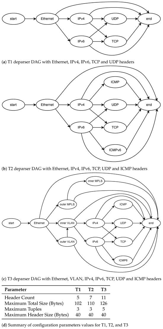
Figure 1.
Example of deparser DAGs and their associated template boundaries.
2.1.2. Software Optimizations for Overlay Memory Generation from P4
Once the boundaries have been defined and the hardware synthesized accordingly, the deparser must be configured to handle different combinations of protocol headers. This is achieved through a memory-resident overlay control table that stores precomputed metadata for each legal emission path. These schedules are generated by a companion software core that analyzes the JSON output of the P4 compiler and derives the necessary emission parameters from the deparser DAG.
Each configuration entry is indexed by a unique path identifier or header validity bitmap (config_addr) and contains:
- The emission order of headers,
- Start offsets and lengths of each header within the PHV bus,
- Emission positions in the serialized output stream,
- Alignment padding, and inter-header spacing,
- The number of bus-sized chunks per header,
- Total cycle count and payload delay.
This structured metadata allows the hardware to reconstruct packets correctly for any P4 program within the bounds, without resynthesis. Algorithm 1 presents the pseudo-code for extracting the overlay configuration entries. The use of each parameter to enable a generic header-agnostic datapath will be explained later sections.
The overlay configuration tables are generated by a lightweight, fully automated software toolchain that operates directly on the P4 compiler’s JSON output. The workflow in Figure 2 consists of three stages. First, the tool parses the P4C-generated JSON file and extracts all relevant protocol metadata, including header definitions, field sizes, parser states, transition conditions, and extraction operations. Second, using this information, it reconstructs the DAG and enumerates all reachable protocol paths. Each path is assigned a validity bitmap and a deterministic header-emission order. Third, for every path, the tool computes the full overlay configuration entry required by the deparser. Since the analysis involves only graph traversal and simple arithmetic over header metadata, the end-to-end generation process completes in a few tens of milliseconds for representative P4 programs. Crucially, no resynthesis, recompilation, or hardware regeneration is required.
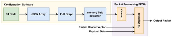
Figure 2.
Proposed compilation workflow for generating configuration for the deparser.
Beyond specifying the format of each configuration entry, it is also necessary to account for the configuration memory’s size and access latency. If each overlay entry has width and the total number of valid paths from the deparser DAG is , then the required configuration-memory footprint is
The configuration table maps to embedded block memories on FPGA, which offer discrete depth and width granularities and allow efficient packing of intermediate-sized tables. This means that the configuration memory typically occupies only a few percent of the total available BRAM resources on FPGA, depending on and . Accessing an entry in the configuration memory introduces fixed, architecture-defined read and write latencies determined solely by the characteristics of the underlying FPGA memory primitives. Let denote the memory-read latency and the memory-write latency associated with updating the configuration table or routing its fields to the emission logic. The worst-case lookup latency to read a single config is therefore
| Algorithm 1: Overlay Configuration Memory Generation |
 |
In the current implementation, the access interface to the configuration memory uses a lightweight valid–address–data protocol, which introduces no additional cycle overhead beyond the native read/write latency of the memory primitive. If a custom wrapper is added then the wrapper’s handshake and transport latency must also be included in the total access time. In such cases, the effective per-access latency becomes
where accounts for any arbitration, handshaking, framing, or transfer delays introduced by an external interface wrapper, and in the present design, this term is zero. When reprogramming the entire configuration table, the total update time scales with the number of entries due to it’s pipelined nature. Assuming each entry is written once, the worst-case full-configuration programming time is
and, in real time,
This provides an upper bound for reloading all overlay entries; in most deployments, only a subset of entries requires updating when protocol configurations evolve.
3. Overlay Hardware Architecture
3.1. Architectural Overview
The deparser plays a critical role in the PISA pipeline Figure 3a by reconstructing outgoing packets from the Packet Header Vector (PHV) and payload. The proposed recursive-select deparser Figure 3b organizes configuration control separately from packet data processing. It consists of two main blocks: the configuration memory and the deparser core, which communicate through control and data interfaces to enable scalable packet reconstruction without resorting to dynamic routing logic. The configuration memory stores software-generated overlay tables indexed by a per-packet validity bitmap. The configuration entry specifies the emission order, PHV offsets, output offsets, alignment requirements, chunk scheduling, and payload timing for each legal protocol path. At runtime, the control logic retrieves the active entry and provides these parameters to the deparser core.
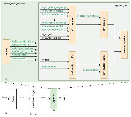
Figure 3.
(a) PISA architecture comprising a Parser, Match–Action processing stages and a Deparser. (b) Recursive-Select Deparser architecture and sub-blocks.
The deparser core in Figure 3b comprises five sub-blocks:
- PHV_operator,
- PHV_streamer,
- payload_delay,
- payload_aligner, and
- streamer_selector.
Guided by the control information, the PHV_operator extracts the required header segments according to the specified offsets and lengths. These segments are then streamed as contiguous bus-width words by the PHV_streamer, avoiding costly byte-level crossbars. The payload is held in the payload_delay and then aligned to the bus boundary by the payload_aligner. Finally, the streamer_selector appends the payload to the emitted headers, yielding the reconstructed packet.
The recursive-select execution model denotes a uniform, header-agnostic loop: select the next scheduled header, resolve its per-packet size and PHV offset, stream its bytes if valid, then advance the output pointer. This process is repeated up to the maximum bound value on headers per path. Because only overlay-provided indices, offsets, and lengths are consumed, the same hardware boundaries supports different P4 programs within the configured bounds by updating configuration entries rather than resynthesizing hardware. Overall, this modular architecture cleanly decouples static datapath logic from runtime control, preserving high throughput while enabling runtime reconfiguration. Operational details for a single-header combination are given in Section 3.3.
3.2. Sub-Blocks
The proposed overlay deparser comprises several interconnected sub-blocks, each responsible for a specific function in the reconstruction pipeline. As illustrated in Figure 3, these blocks collectively manage configuration, control, header processing, and payload handling to ensure correct and efficient packet emission. The main sub-blocks are summarized below:
- Configuration memory: overlay entries per legal path (emission order, PHV offsets/lengths, output positions, chunk counts, delay/alignment).
- Control logic: selects the active entry, computes the header count , and sequences exactly iterations of the recursive-select loop.
- PHV_operator: extracts each valid header, positions it at the correct output offset, and OR-reduces slices into a contiguous header region (no dynamic crossbar).
- PHV_streamer: serializes bus-width words at one word per cycle in the scheduled order.
- payload_delay: buffers payload for the programmed delay to match header emission time.
- payload_aligner: applies a single alignment computed from the total header bytes (no per-header padding) for seamless, byte-accurate handoff.
- streamer_selector: multiplexes header and payload at the exact boundary cycle, without bubbles.
Together, these components form a modular datapath that avoids dynamic crossbars while guaranteeing line-rate emission. The following sections explore their interaction further, explaining the per-packet execution flow and timing behavior in more detail.
3.3. Per-Packet Execution (Single Header Combination)
At the input cycle, the deparser receives the PHV data vector, the per-header validity bitmap, and the first payload word with its valid. The control logic uses the bitmap to index the overlay configuration entry for this packet path. Each incoming packet triggers a lookup into the overlay configuration memory. While the entry is being fetched, the PHV, bitmap, and the payload are buffered. This ensures that data and control emerge in step with the memory read latency, keeping them time-aligned. Once the entry is available, the control logic sequences exactly iterations of the recursive-select loop, where is the number of valid headers. In each iteration, the PHV operator slices and repositions one header, which is then streamed toward the output. After all headers are emitted, the payload delay block releases the buffered payload at the correct boundary, fusing the last header word with the first payload bytes. This process guarantees bubble-free handoff between headers and payload.
The configuration entry specifies which headers are present, their PHV start offsets and lengths, their output start positions, and the number of bus-sized chunks each header occupies. Once available, the header-assembly stage (PHV_operator) extracts each valid header from its predefined slice of the PHV, masks it to its exact length, shifts it to the correct output position, and OR-reduces the result into an intermediate header buffer. This operation converts header bytes that were scattered across the PHV bus into a single contiguous region of header data in the correct order, without requiring a dynamic crossbar.
The PHV_streamer then emits this contiguous header region one bus-width word per cycle. During this time, the payload remains buffered for exactly as many cycles as needed to match the total header emission time (, defined in Section 3.4). If the final header word is only partially filled, the payload_aligner shifts the payload by the precomputed offset (, defined in Section 3.4) so that the remaining bytes of that word are completed by the first payload bytes in the same cycle. From the next cycle onward, only the payload is selected at the output. After the handoff, payload streaming continues at one word per cycle with the same alignment established at the boundary. The final payload word carries its own byte-valid count, and no bubbles are inserted between the tail of the header region and the start of the payload.
Table 2 summarizes the notation for timing parameters introduced in Section 3.4. These symbols will be used throughout the latency and alignment analysis of the PHV operator and streamer pipeline.
Table 2.
Notation summary for timing and alignment analysis.
3.4. Timing and Alignment Mathematics
Let B be the bus width in bytes. For each valid header h, let be its PHV start offset (bytes), its length (bytes), and its output start position (bytes). Let denote the per-header validity bitmap and define the header count.
which is the number of headers in the path and therefore the number of loop iterations in the recursive-select deparser. The total header footprint is
To calculate the delay, we need to know the header word count. Headers occupy cycles (header word count). Let denote the configuration-memory read latency (cycles). The payload delay is therefore
Let the header tail be the number of valid bytes in the final header word ( means the last header word is full). The aligner offset applied to the payload is
To avoid a spurious one-word shift, modB is applied after computing ; equivalently, the piecewise form is
If , the last header word contains header bytes and bytes from the (shifted) payload in the same cycle; from the next cycle onward, only the payload is emitted.
3.4.1. PHV Operator
Table 3 summarizes the notation used for the PHV operator. These symbols describe how headers are sliced, shifted, and reconstructed, and will be referenced throughout Section 3.4.1.
Table 3.
Notation summary for symbols used in the PHV operator.
The PHV operator is responsible for extracting protocol headers from the PHV and placing them into their correct positions in the output stream. The operator is decomposed into two stages to avoid the quadratic number of cross-point cost of a full byte-level crossbar: slice selection with MSB alignment and shift-based repositioning as demonstrated in Figure 4a.
Figure 4.
PHV operator architecture.
First stage is MSB-aligned slice selection. The slicer, as shown in Figure 4b, produces a fixed -byte window from the PHV starting at byte offset (MSB-first indexing). If , the missing MSB portion is zero-padded. If the requested window runs past the PHV boundary (), the missing LSB portion is zero-padded. After applying the specific situation that applies, the output is always a -byte vector with valid PHV bytes aligned to the MSB side and any shortfall filled with zeros. Second stage is Shift-based re-positioning. In the second stage, as shown in Figure 4c, each MSB-aligned slice is then placed at its configured packet offset . Instead of routing every byte through a crossbar, the design applies a logical shift by
which displaces the slice from its MSB alignment to the target output offset. After shifting by , the slice is masked to its actual header length to ensure padded bytes are suppressed. All slices are then combined with a bitwise OR:
where is the shifted and masked slice of header h, and ⋁ denotes a logical OR across all slices. This guarantees that headers are reconstructed at the correct offsets without overlap, while avoiding the quadratic crosspoint complexity of a crossbar.
Complexity analysis for the proposed design conveys that a conventional byte-level crossbar requires byte multiplexers, since each of the output positions must be able to select from all PHV bytes. In contrast, the proposed PHV operator avoids this quadratic cost by decomposing reconstruction into three more straightforward steps: slice selection, per-header alignment, and output positioning.
- Slice selection: An -byte contiguous window is extracted from the -byte PHV starting at offset . This can be achieved by a barrel-shaped depth shifter applied on bytes, giving a cost of .
- Re-positioning: Each valid header requires two shift operations inside the concatenator. First, the slice is right-shifted so that its valid bytes occupy the least significant positions, with zero padding applied to the left. Second, the slice is left-shifted to its final packet offset . Both operations touch at most bytes per header, so the overall cost per header remains .
- Masking and OR-combination: After shifting, each slice is masked to its true length and OR-combined into the contiguous header buffer. Across all headers, this results in work, with an OR-tree depth of .
The overall complexity of the operator is therefore:
Although the OR-combination stage involves a reduction tree of depth , this factor reflects the parallel logic depth rather than additional operations, and thus does not affect the overall asymptotic work complexity. This complexity grows linearly with the maximum header size and the number of valid headers , rather than quadratically with as in a full crossbar. In practice, both and are much smaller than , which leads to substantial reductions in LUT usage and easier timing closure on FPGAs. In the VHDL design, the phv_slicer module implements slice selection, while the phv_concat module performs re-positioning, masking, and OR-combination without requiring a wide broadcast network.
3.4.2. PHV Streamer
The PHV streamer serializes header chunks produced by the PHV Operator onto the output data bus. Driven by configuration fields such as the number of chunks and the start position, it emits one bus-width word per cycle. Internal counters track the progress of emissions to ensure that multi-word headers are transmitted contiguously before advancing to the next header in the schedule. Once a header is completely processed, the counters reset automatically, enabling seamless back-to-back emission of headers.
3.4.3. Payload Delay Buffer
After all headers in a packet are emitted, the payload must be forwarded without violating timing or alignment constraints. In our design, the payload data is buffered during the header emission cycles and then released after a programmed delay derived from the configuration memory. This controlled buffering ensures that payload emission begins precisely when the last header chunk has been transmitted, preventing data hazards and alignment errors.
Its size scales with the payload bus width and the maximum payload-delay depth derived from the longest path of the DAG:
Since both parameters scale linearly with protocol complexity, B is set by the target throughput requirement and depends on the longest header chain, the resulting memory footprint also scales linearly. In terms of latency, the payload delay buffer introduces a fixed, architecture-defined memory-access delay that depends only on the characteristics of the underlying FPGA memory primitives and not on the buffer depth. Let denote this fixed access latency (in cycles). The worst-case buffering latency, measured from the cycle at which a payload word is written into the buffer to the cycle at which it is first read out, is then:
3.4.4. PHV–Payload Aligner
Due to variable header sizes and alignment requirements, the transition from header emission to payload emission often requires byte shifting or word realignment. The phv_aligner module performs this task, adjusting the starting point of the payload data so that it follows immediately after the last emitted header byte. This alignment step uses precomputed padding values from the configuration memory, ensuring zero gaps and maintaining protocol compliance without introducing dynamic shifting logic in the critical path.
3.4.5. Streamer Selector
The streamer_selector arbitrates between multiple possible output sources that are the PHV stream for header data and the payload buffer for payload data. Based on runtime control signals derived from the emission schedule, the selector switches the active data source at the exact cycle when the header-to-payload transition occurs. This ensures a seamless concatenation of headers and payload in the output stream, preserving throughput and avoiding redundant cycles.
Overall, this modular microarchitecture, backed by precomputed overlay control tables, eliminates wide, dynamic routing fabrics while enabling runtime flexibility. Each block has a clearly bounded function, mapped to synthesizable VHDL modules, allowing the architecture to scale to diverse P4 workloads within the defined boundary limits.
3.5. Deparser Packet Flow
Figure 5 illustrates the detailed flow of packet reconstruction in the proposed recursive-select deparser. The figure shows how headers are extracted from the PHV, realigned, padded if necessary, concatenated into a contiguous block, serialized, and finally merged seamlessly with the payload. Each subfigure highlights one step of the datapath, emphasizing how the design avoids costly dynamic crossbars while maintaining precise alignment.
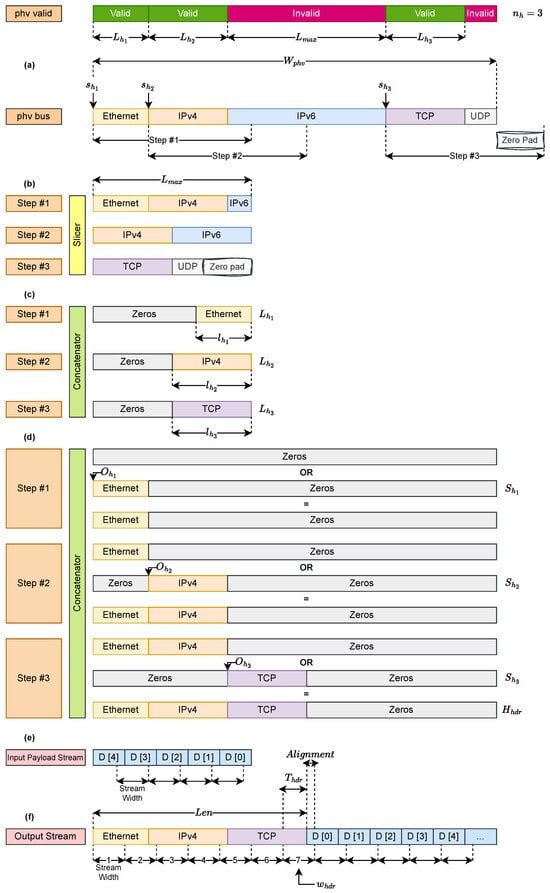
Figure 5.
Deparser Packet Flow.
- Figure 5a: Header Extraction from PHV
The Packet Header Vector has width (Bytes) and stores all parsed headers at fixed offsets together with their validity bits V. The slicer module inspects the bitmap V and extracts a fixed -byte slice starting at offset . If the requested window extends beyond the PHV boundary, the missing portion is zero-padded so that the output is always an -byte vector.
- Figure 5b: Fixed-Size Chunks
Each extracted slice is represented as a fixed-size chunk of bytes. Although the actual header length is , standardizing to ensures uniform handling for all headers. These chunks may include unused or overlapping bytes, but they simplify downstream logic by enforcing a common width.
- Figure 5c: Zero Padding and Right Alignment
To isolate only the valid portion, each slice of length is shifted right so that the valid bytes of header h occupy the vector’s least significant side (LSB). The remaining positions are zero-padded. Formally,
- Figure 5d: Contiguous Header Reconstruction
Each header h is placed at its absolute output offset , which is computed as the cumulative length of all previously emitted headers:
The placement is achieved by shifting the MSB-aligned slice by this offset:
This formulation is consistent with the shift distance definition introduced in Section 3.4.1, where
In the cumulative-offset view of Figure 5d, the slice is already MSB-aligned, so the displacement reduces to .
Finally, all shifted slices are combined with a bitwise OR to form the contiguous header block:
where is the number of valid headers in the path.
- Figure 5e: Streaming of Header Block
The PHV_streamer serializes into bus-width words of B bytes, one per cycle. The number of header cycles and the corresponding payload delay follow directly from the derivations in Section 3.4.
- Figure 5f: Header–Payload Handoff
At the boundary, the payload_aligner applies a precomputed offset so that the first payload bytes fill any unused space in the final header word. The exact expressions for residual bytes and alignment ( and ) are given in Section 3.4.
Overall, Figure 5 demonstrates the recursive-select execution model: the deparser iterates through valid headers, extracts them at offsets , right-aligns them to length (producing ), shifts them to their output offsets (producing ), OR-combines them into , streams bus words through the PHV_streamer, and finally appends the payload with alignment as derived in Section 3.4. By replacing dynamic crossbars with slice-and-shift logic guided by overlay control metadata, the architecture scales linearly with header size and header count , while sustaining one bus-width word per cycle at runtime.
3.6. Templated Hardware Architecture
The templated architecture is introduced as a compile-time variant of the overlay. It preserves the same recursive-select datapath and header reconstruction pipeline but removes runtime configurability by eliminating the configuration memory and its associated control interface. Instead of storing per-path control information in memory, it replaces these contents with VHDL generics that are resolved during synthesis. This approach preserves protocol independence within predefined template bounds while binding control parameters statically. The templated architecture is motivated by ease of regeneration and design stability. Unlike compiler-specialized approaches that regenerate RTL for every P4 program, the templated variant maintains a fixed hardware structure and avoids automatic code generation. This makes regeneration significantly simpler from a design and usability perspective, because only generic parameters are updated rather than regenerating tailored RTL. Although it still requires resynthesis, it avoids build-chain complexity and provides a reusable and maintainable hardware implementation.
For simpler protocol graphs, the templated variant uses fewer resources compared to the overlay since it removes the configuration memory and runtime selection logic. However, as protocol graphs grow in complexity, the number of valid header combinations increases and the control logic must explicitly encode these combinations. This creates a statically synthesized decision tree that expands proportionally to protocol variability. Since this decision structure grows in logic rather than memory, LUT usage and routing complexity increase more rapidly than in the overlay. The overlay, by contrast, reserves hardware based on template bounds and stores per-path behavior in memory. This introduces modest fixed overhead for small designs, but its advantage becomes clear as protocol complexity increases. Since additional protocol combinations only expand memory contents rather than logic, growth remains more predictable. The templated design therefore serves as an intermediate option: easier to regenerate than compiler-specialized RTL and lighter than an overlay for simple configurations, but increasingly inefficient as the per-path decision tree grows with protocol complexity.
4. Results
This section presents the results obtained with the proposed recursive-select and templated overlay deparser. We begin by describing the experimental setup and the protocol stacks under test. We then analyze FPGA resource scaling to validate the theoretical complexity model and to show how the slice-and-shift operator eliminates the rigidity of crossbars. Next, we compare our results with those reported for previously published specialized deparsers. Finally, we demonstrate runtime programmability by reconfiguring the synthesized hardware to operate with the Access Gateway Function (AGF) stack’s DAG as described [30]. To evaluate scalability beyond isolated bus-width or protocol demonstrations, we deliberately stress the architecture across increasing graph complexity, wider buses, and growing PHV sizes. This section shows that resource usage is governed primarily by protocol depth rather than PHV width, confirming that the recursive-select overlay scales predictably even as protocol graphs grow in size and heterogeneity.
The design was synthesized on a Xilinx Virtex UltraScale+ (XCVU3P) device, selected for both technical and methodological reasons. The same FPGA family has been used in prior deparser studies, enabling fair and direct comparison with established baselines. The XCVU3P is also widely deployed in industrial FPGA accelerators making it a practical and representative target for P4-programmable data-plane research. In addition, its balanced mix of LUTs, flip-flops, BRAM, and high-speed transceivers provides ample resources to implement both the templated and overlay variants without routing congestion or resource saturation. To evaluate the design, throughput is obtained from post-synthesis and post-implementation results, using the standard calculation followed in prior FPGA deparser studies. Functional validation is ensured through an automated Python 3.12.-driven VHDL simulation script that exercises all valid header paths, PHV_valid patterns, and supported bus-width configurations, and validates each scenario to ensure complete coverage of header ordering.
We evaluated three protocol stacks of growing complexity:
- T1: Ethernet, IPv4/IPv6, TCP/UDP
- T2: Ethernet, IPv4/IPv6, TCP/UDP, ICMP/ICMPv6
- T3: Ethernet, double VLAN, double MPLS, IPv4/IPv6, TCP/UDP, ICMP/ICMPv6
For each stack, boundary overlay parameters were derived from the deparser DAG and enforced at synthesis time. These include the maximum number of headers , the maximum per-header size , the maximum depth, and the total PHV footprint and bus width. Concretely, T1 required , Bytes with a PHV footprint () of 102 Bytes; T2 expanded to , Bytes with a PHV footprint of 110 Bytes; and T3 exercised the upper bound with , Bytes and a PHV footprint of 126 Bytes, as shown in Figure 1d. Within these template bounds, runtime adaptation of emission order, header offsets, and alignment is achieved entirely through overlay configuration memory.
In addition to resource scaling, timing behavior is a key factor in evaluating deparser performance. While graph complexity and bus width influence logic growth, they also determine the pipeline depth and overall emission latency. The proposed overlay architecture introduces a fixed baseline latency of nine clock cycles, plus the maximum number of iterations required for recursive selection, five in the most complex case (T3). This latency originates from additional stages introduced by the recursive-select architecture, including a two-cycle configuration-memory fetch, slice selection and shift alignment performed by the PHV_operator, sequencing of the recursive loop and streamer activation by the control logic, and the payload-delay and aligner stages that ensure correct emission order. After this offset, the latency depends on the total number of header bytes relative to the bus width. The worst-case packet emission delay is therefore expressed as:
With wider buses, more header bytes are emitted per cycle, reducing the variable component of the latency compared to narrower datapaths.
To provide a complete view of system behaviour, the memory characteristics of the overlay were assessed alongside the pipeline-latency analysis. Table 4 reports, for T1–T3 configuration, the configuration-memory footprint , the payload-delay buffer size , the corresponding BRAM usage on the XCVU3P device, and the worst-case latencies derived from the models in Section 2.1.2 and Section 3.4.3. For all evaluated stacks, both memories exhibit fixed, device-characterized read and write latencies. The configuration memory requires one write cycle to update an entry and two read cycle to fetch it during operation. At the same time, the payload-delay buffer introduces the same fixed access delay for both read and write operations, as determined by the underlying UltraScale+ memory primitives.
Table 4.
Configuration-memory and payload-delay buffer characteristics across bus widths for the overlay deparser.
Since each configuration entry is written in exactly one cycle, the total time required to reprogram the configuration memory grows linearly with the number of valid paths extracted from the deparser DAG. The worst-case programming time is therefore proportional to the number of entries. On UltraScale+ devices, both the configuration memory and the payload-delay buffer are implemented using distributed BRAM primitives, which internally consist of paired BRAM18 blocks forming logical BRAM36 units. This structure allows the memories to be mapped efficiently onto fixed-width BRAM tiles, with each table or buffer aligned to the native port widths of the underlying blocks.
To provide a quantitative view of memory occupancy, the BRAM usage is expressed as a percentage of device resources. The XCVU3P device contains 720 BRAM36 blocks in total. For the smallest configuration, corresponding to the T1 stack at 64 bits, the overlay architecture consumes 2.5 BRAM36 blocks and the templated design consumes 1 BRAM36 block, which corresponds to 0.35 percent and 0.14 percent of the available BRAM resources. For the largest evaluated configuration, corresponding to T3 at 512 bits, the templated design requires 7.5 BRAM36 blocks and the overlay requires 9.5 BRAM36 blocks, corresponding to 1.05 percent and 1.33 percent of the device capacity. These values confirm that even at the highest complexity levels the memory footprint of both designs remains very small relative to the available resources. For the proposed architecture, bandwidth limitations are not imposed by either memory components, since both operate well within the capacity of the underlying BRAM primitives. The configuration memory is written in a single cycle per entry during reprogramming and is read with a fixed two-cycle latency during operation. The payload delay buffer is accessed once per cycle at the system clock frequency, with one bus-width word issued sequentially on every cycle, and its access pattern remains strictly linear and free of contention. Since both memories are operating at the same frequency as the deparser pipeline and are only used for control lookups and streaming, their bandwidth demands remain modest, and no bottlenecks arise for any of the evaluated bus widths. These characteristics, along with the resulting memory footprints, latencies, and programming times for each test stack, are summarized in Table 4. The table further reports the measured overlay reconfiguration latency, which ranges from approximately 13 ns for the smallest evaluated configuration T1 graph to 59 ns for the largest configuration graph T3.
The synthesis data is demonstrated in Table 5 and implementation data is shown in Table 6. For the overlay, LUT and FF usage remain below 15 k even for T3 with bus size of 512 while sustaining ≈296 Gb/s, whereas the templated variant surpasses this value as the graph expands. This behavior confirms that the recursive-select overlay preserves throughput while providing more predictable, balanced resource scaling. Table 5 compares the recursive-select framework, including both the templated and overlay implementations, against representative FPGA deparsers. Compared with the bit-selector pipeline of Luinaud [25], which hardwires concatenation schedules at compile time, both variants sustain higher throughput within a comparable area budget. For T2 with bus size of 256, the templated deparser achieves up to 1.45× higher throughput (≈174 Gb/s vs. 120 Gb/s), while the overlay maintains 1.2–1.4× improvement at modest additional logic cost. Against the symbolic specialization approach of Luinaud [26], which minimizes area by entirely eliminating runtime control, the templated and overlay deparsers exhibit 1.6–10× higher LUT usage but retain competitive throughput (up to ≈296 Gb/s for T3 at bus size of 512 vs. 311 Gb/s in [26]) while uniquely supporting dynamic reconfiguration. The key distinction is that both proposed designs are reusable across multiple P4 workloads, whereas compiler-specialized pipelines must be regenerated for each configuration. The recursive-select architectures more than double this throughput without relying on replicated or time-multiplexed datapaths. The slice-and-shift datapath used in both the templated and overlay variants achieves comparable throughput and scalability with significantly lower structural complexity.
Table 5.
Comparison of FPGA resource usage and throughput across bus widths for the proposed recursive-select deparser and prior FPGA deparsers.
Table 6.
Comparison of Deparser Implementation with Previous Work with an Output Bus of 512 Bits.
Implementation-level results in Table 6 reinforce these findings for a fixed 512-bit datapath. The overlay sustains approximately 232–254 Gb/s after place-and-route, while synthesis estimates in Table 5 reach about 296 Gb/s. This difference reflects timing closure at implementation and remains well above prior work. LUT usage stays below 15 k and BRAM utilization under 10.5 blocks, outperforming Xilinx SDNet [24]. The deparser generated with Xilinx SDNet consumes ~8× more LUTs and ~10× more FFs than the deparser generated in this work. The templated design achieves slightly better timing closure for the simpler graphs (T1–T2). Still, it exhibits steeper resource growth for T3 due to its fully unrolled structure, confirming that overlay-based configurability scales more efficiently with increasing graph complexity. Compared with Luinaud [25], which attains 140–220 Gb/s with larger LUT footprints and higher BRAM usage, the two proposed designs reach higher throughput with reduced reliance on wide multiplexers and deep buffers. Compared with Luinaud [26], the overlay sustains slightly lower peak throughput for T3 (approximately 296 Gb/s synthesis versus 310 Gb/s reported) but remains fully reconfigurable at runtime, a capability absent from compile-time-specialized designs.
The observed scalability behavior is further quantified using the normalized LUT/Gbps metric in Table 6, which shows that the overlay design maintains an almost constant cost across all protocol stacks (57.5–61.7 LUT/Gbps from T1 to T3) while providing full runtime programmability. For the most complex configuration (T3), this corresponds to approximately twice the normalized cost of the specialized and optimized symbolic design of Luinaud et al. [26] (≈30 LUT/Gbps). This remains lower than the compile-time specialized deparser of Luinaud et al. [25] (≈100 LUT/Gbps), and is more than an order of magnitude lower than the results obtained with the Xilinx SDNet baseline [24] (>600 LUT/Gbps). The templated variant spans 32.8–79.2 LUT/Gbps, achieving competitive efficiency for simpler graphs and increasing for deeper DAGs due to static unrolling. To further validate runtime programmability while stressing scalability beyond T3, we evaluated the overlay architecture using a more demanding configuration derived from T3 by augmenting it with IPv6 extension headers. This extended configuration preserved the same maximum per-header size (40 bytes) but increased structural complexity to 13 total nodes, 7 conditional transitions, and a PHV footprint of 142 bytes. Table 7 summarizes the synthesis results for this configuration. Since the overlay is synthesized once for the most demanding configuration within its template bounds, it naturally accommodates any subgraph without resynthesis. In practice, this means that a single bitstream generated for the extended T3 configuration can also execute T1, T2, and T3 by simply loading their respective configuration memory at runtime. This downward compatibility is inherent to the overlay approach meaning that when synthesizing for the worst-case graph, it can safely covers all simpler protocol stacks within the same design envelope.
Table 7.
Synthesis/implementation results for the Extended T3 configuration under the proposed overlay design.
Furthermore, runtime programmability is not limited to protocol subgraphs from the same stack family. As demonstrated using the Access Gateway Function (AGF) stack [30], which consists of 10 headers (Ethernet, IPv4, 802.1Q, 802.1AD, UDP, GTP-U, 5WE, PPPoE_V1/V2, PPPoE_V1, and the PDU Session Container) with a maximum header size of 20 bytes and 7 transitioning nodes, the overlay can be repurposed for entirely different protocol graphs. Only the configuration memory contents are regenerated to encode AGF-specific emission order, header offsets, and alignment, while the datapath remains unchanged. This demonstrates horizontal adaptability across heterogeneous protocol applications. Together, these results confirm that the overlay enables hardware reuse across both sub-stacks and new protocol configurations without resynthesis, validating its ability to support diverse P4 workloads using a single bitstream. To reprogram the overlay for a new protocol stack, only the configuration memory is updated, without modifying or resynthesizing the hardware. The P4 JSON description of the new program is analyzed to extract all legal emission paths and compute the associated control parameters. For each validity bitmap, one configuration entry is produced that contains per-header fields: the PHV start offsets , the header byte lengths , the output offsets , and the number of bus-width chunks . Each entry also includes path-level metadata: the total header length , the payload alignment , the payload delay , and the number of valid headers .
Figure 6 evaluates the impact of increasing the output bus width from 64 to 512 bits for both proposed overlay and templated architectures. while compile-time–specialized designs [26] have reported a significant increase in resource usage when widening the output bus including LUT usage for the T3 configuration increases from 1.05 k at 64 bits to 9.40 k at 512 bits and the FF usage increases from 375 to 3.13 k, corresponding to an 8.9× and 8.3× increase respectively for an eightfold bus-width expansion. In contrast, the proposed recursive-select architecture exhibits a much smaller growth in resource usage for the same increase in bus width, LUT utilization increases from 8.05 k to 14.96 k and FF utilization increases from 8.46 k to 10.77 k, corresponding to only 1.9× and 1.3× growth respectively.
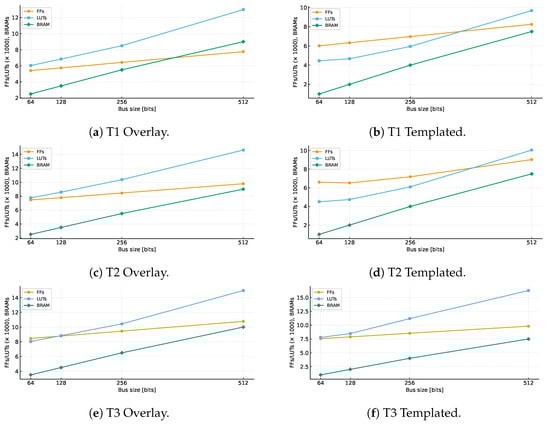
Figure 6.
FPGA resource utilization across bus widths of 64–512 bits for test graphs T1–T3 under the proposed overlay and templated architectures. Each subplot reports LUT, FF, and BRAM scaling with bus size.
Figure 7 evaluates the scaling behavior of the proposed overlay architecture with respect to protocol complexity and PHV width. Figure 7a isolates the effect of increasing the number of supported protocol headers while fixing the output bus width at 512 bits. The results show that LUT and FF utilization grow approximately linearly with the number of headers . For example, increasing protocol depth from T1 () to T3 () raises LUT usage from 12.99 k to 14.97 k and FF usage from 7.76 k to 10.78 k, corresponding to only 15% and 38% growth respectively. This confirms that resource usage is primarily dominated by header count, consistent with the analytical complexity term derived in Section 3.4.1. In contrast, compile-time–specialized designs must replicate logic for each protocol path and therefore scale poorly as protocol graphs grow. Figure 7b evaluates the sensitivity of the architecture to PHV width , which reflects the total header footprint extracted from the parser. Resource usage increases only slightly as grows from 102 bytes (T1) to 142 bytes (Extended T3), with LUT usage increasing from 12.99 k to 16.35 k (26%) and FF usage from 7.76 k to 11.40 k (47%). This mild growth validates the weak logarithmic dependency predicted by the term. Unlike byte-level crossbar implementations, which exhibit quadratic growth with PHV width, the recursive-select architecture uses slice extraction and shift-based alignment, avoiding wide multiplexers and routing congestion. Overall, Figure 7 shows that protocol depth is the dominant scaling factor, while PHV width has a secondary and controlled impact on FPGA resource usage. These results highlight that scaling trends are dominated by control complexity rather than datapath width, which motivates a closer comparison between the overlay and templated implementations, since the templated version encodes control logic statically while the overlay stores it compactly in memory and therefore scales more efficiently for larger protocol graphs.
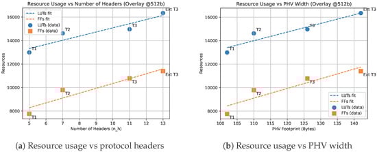
Figure 7.
Resource scaling behavior of the proposed overlay architecture: (a) variation with increasing number of protocol headers; (b) variation with PHV width.
Compiler-specific deparsers require complete RTL regeneration followed by synthesis and place-and-route whenever the protocol graph changes. On contemporary FPGA toolflows, these steps often incur tens of minutes to several hours, which limits their practicality in environments with evolving protocols or multiple coexisting applications. In contrast, the proposed overlay deparser applies behavioral changes through lightweight updates to configuration memory, completing in nanoseconds without halting the datapath or regenerating hardware. Although this generic architecture introduces a higher initial cost than a specialized deparser for very simple graphs, its hardware complexity scales far more favorably as protocol structures grow. The slice-and-shift operator increases approximately linearly with the number of headers and only weakly with the PHV width, while crossbar permutation-engine designs incur complexity and compiler-specialized deparsers scale with . As a result, the overlay grows with a smaller slope. At the same time, the initial gap is noticeable for T1-level graphs, but narrows for T2 and T3, confirming that the proposed design becomes increasingly efficient alternative as protocol graphs deepen and PHV widths expand.
Taken together, these results show that the recursive-select framework redefines the performance-versus-programmability boundary for FPGA deparsers. For small and moderately complex graphs (T1–T2), the templated implementation achieves slightly lower resource usage than overlay by eliminating configuration memory and dynamic control. However, as graph complexity increases, the static unrolling in templated and compiler-specialized designs results in rapid logic replication and timing closure stress. Unlike the templated variant, whose logic footprint grows rapidly with graph complexity, the overlay exhibits a much flatter resource growth trend because additional protocol paths expand memory contents rather than LUT logic. This makes it increasingly advantageous for deeper and more diverse protocol graphs. This trend is confirmed by Table 7, where the overlay handles an extended T3 configuration (13 headers, 7 transitions) with only a modest increase in LUTs and FFs, while remaining within timing and BRAM limits. For the compiler-driven specialization the logic must be regenerated for every protocol stack change and scales more steeply beyond fixed header pipelines, while the overlay sustains predictable linear growth and reusability from T1 through extended T3 and the latter can be used for all other sub-graphs without resynthesis. These results indicate that the overlay is advantageous in scenarios where protocol configurations evolve, offering reusable hardware with controlled resource growth. In contrast, static and specialized designs must be regenerated and scale less predictably.
5. Conclusions
This work presented a unified hardware–software framework for FPGA-based P4 deparsers that bridges compile-time specialization and runtime reconfigurability. The proposed recursive-select architecture replaces wide dynamic crossbars with a slice-and-shift datapath, achieving near-linear computational complexity and predictable scalability as protocol depth and datapath width increase. Two architecture variants were introduced: a templated deparser, optimized for static deployments with fixed protocol graphs, and an overlay deparser that stores per-path behavior in configuration memory to enable runtime adaptation. Reported results show that for small to moderate protocol graphs (T1–T2), the templated implementation achieves a lower area footprint and slightly higher clock frequency due to the absence of configuration memory. However, as graph complexity increases (T3 and beyond), compiler-specialized and static approaches exhibit steeper growth in logic utilization and face timing closure challenges due to logic replication. In contrast, the overlay maintains a flatter resource scaling trend, sustaining line-rate throughput up to 296 Gb/s (synthesis) and 241–254 Gb/s (implementation) on a 512-bit datapath while remaining within modest LUT and BRAM budgets. These findings validate the analytical complexity model and confirm that runtime-configurable deparsing can be achieved without crossbar switching. Compiler-specialized deparsers remain programmable but require complete regeneration of RTL, synthesis, and place-and-route for every protocol update. This limits their practicality when protocol stacks evolve or when multiple P4 applications must share FPGA resources. In contrast, the recursive-select overlay accepts a modest area overhead and a slight reduction in maximum clock frequency compared to fully specialized designs in exchange for long-term flexibility: protocol behavior is defined in configuration memory, allowing in-field updates without modifying hardware or interrupting service. This capability enables hardware multitenancy, where different tenants or applications may load distinct protocol configurations on the same FPGA fabric.
This work opens several avenues for future research. A direct extension of the framework is the construction of fully overlay-defined PISA pipelines, where the parser, match–action, and deparser stages are all controlled by configuration-memory tables, enabling end-to-end pipeline reconfiguration without regenerating RTL. The overlay approach is well-suited to dynamic, multi-tenant data-plane designs, allowing each tenant to operate with distinct protocol stacks, header formats, or service policies. Such capabilities align closely with emerging network-slicing requirements, where multiple virtual network instances must coexist on shared FPGA resources. Another avenue for advancement involves integrating the overlay design with FPGA partial reconfiguration so that only the affected region of the pipeline is updated when protocol-graph limits or header layouts change, eliminating the need for full-design resynthesis.
Overall, this work demonstrates that high performance and runtime programmability can be co-designed in FPGA data planes without sacrificing scalability. Beyond the deparser itself, the overlay approach aligns with the long-term goal of realizing a fully programmable PISA pipeline on FPGA, where the parser, match-action, and deparser stages are all overlay-defined and reconfigurable at runtime. Such architectures enable evolvable packet processing, rapid protocol deployment, and efficient FPGA sharing across heterogeneous workloads, forming a practical foundation for future reconfigurable network systems.
Author Contributions
Conceptualization, P.M.-M., T.O.-B. and Y.S.; methodology, P.M.-M., T.O.-B. and Y.S.; software, P.M.-M.; validation, P.M.-M.; formal analysis, P.M.-M.; investigation, P.M.-M.; resources, Y.S., T.O.-B. and P.M.-M.; data curation, P.M.-M.; writing—original draft preparation, P.M.-M.; writing—review and editing, Y.S., T.O.-B. and P.M.-M.; visualization, P.M.-M.; supervision, Y.S. and T.O.-B.; project administration, Y.S.; funding acquisition, Y.S. All authors have read and agreed to the published version of the manuscript.
Funding
This research was funded by the NSERC Kaloom-Intel-Noviflow Industrial Chair of Professor Savaria IRCPJ-548237-18 CRSNG, by Polytechnique Montreal, and by discovery grant RGPIN-2019-05951 CRSNG (AV: 05295-2014/6574-09) to one of the authors.
Data Availability Statement
The original contributions presented in the study are included in the article, further inquiries can be directed to the corresponding authors.
Conflicts of Interest
The authors declare no conflicts of interest.
References
- Kleinrock, L. An early history of the internet [History of Communications]. IEEE Commun. Mag. 2010, 48, 26–36. [Google Scholar] [CrossRef]
- Cisco. Cisco Annual and Internet Report; Technical Report 3; Cisco: Hong Kong, China, 2018. [Google Scholar]
- Benson, T.; Akella, A.; Maltz, D. Unraveling the Complexity of Network Management 2009. pp. 335–348. Available online: https://www.usenix.org/legacy/event/nsdi09/tech/full_papers/benson/benson_html/ (accessed on 4 December 2025).
- Tennenhouse, D.L.; Smith, J.M.; Sincoskie, W.D.; Wetherall, D.J.; Minden, G.J. A survey of active network research. IEEE Commun. Mag. 1997, 35, 80–86. [Google Scholar] [CrossRef]
- Feamster, N.; Balakrishnan, H.; Rexford, J.; Shaikh, A.; Van Der Merwe, J. The case for separating routing from routers. In Proceedings of the ACM SIGCOMM 2004 Workshops; ACM: New York, NY, USA, 2004. [Google Scholar] [CrossRef]
- Papastergiou, G.; Fairhurst, G.; Ros, D.; Brunstrom, A.; Grinnemo, K.J.; Hurtig, P.; Khademi, N.; Tüxen, M.; Welzl, M.; Damjanovic, D.; et al. De-Ossifying the Internet Transport Layer: A Survey and Future Perspectives. IEEE Commun. Surv. Tutor. 2017, 19, 619–639. [Google Scholar] [CrossRef]
- Kreutz, D.; Ramos, F.M.V.; Verissimo, P.; Rothenberg, C.E.; Azodolmolky, S.; Uhlig, S. Software-Defined Networking: A Comprehensive Survey. Proc. IEEE 2014, 103, 14–76. [Google Scholar] [CrossRef]
- Casado, M.; McKeown, N.; Shenker, S. From ethane to SDN and beyond. ACM SIGCOMM Comput. Commun. Rev. 2019, 49, 92–95. [Google Scholar] [CrossRef]
- McKeown, N.; Anderson, T.; Balakrishnan, H.; Parulkar, G.; Peterson, L.; Rexford, J.; Shenker, S.; Turner, J. OpenFlow. ACM SIGCOMM Comput. Commun. Rev. 2008, 38, 69–74. [Google Scholar] [CrossRef]
- Bosshart, P.; Gibb, G.; Kim, H.S.; Varghese, G.; McKeown, N.; Izzard, M.; Mujica, F.; Horowitz, M. Forwarding Metamorphosis: Fast Programmable Match-Action Processing in Hardware for SDN. In Proceedings of the ACM SIGCOMM 2013 conference on SIGCOMM, New York, NY, USA, 12–16 August 2013; pp. 99–110. [Google Scholar] [CrossRef]
- Bosshart, P.; Daly, D.; Gibb, G.; Izzard, M.; McKeown, N.; Rexford, J.; Schlesinger, C.; Talayco, D.; Vahdat, A.; Varghese, G.; et al. P4: Programming protocol-independent packet processors. ACM SIGCOMM Comput. Commun. Rev. 2014, 44, 87–95. [Google Scholar] [CrossRef]
- Gibb, G.; Varghese, G.; Horowitz, M.; McKeown, N. Design principles for packet parsers. In Proceedings of the Architectures for Networking and Communications Systems, San Jose, CA, USA, 21–22 October 2013; IEEE: New York, NY, USA, 2013; pp. 13–24. [Google Scholar] [CrossRef]
- Mashreghi-Moghadam, P.; Ould-Bachir, T.; Savaria, Y. A Templated VHDL Architecture for Terabit/s P4-programmable FPGA-based Packet Parsing. In Proceedings of the 2022 IEEE International Symposium on Circuits and Systems (ISCAS), Austin, TX, USA, 27 May–1 June 2022; IEEE: New York, NY, USA, 2022; pp. 672–676. [Google Scholar] [CrossRef]
- Mashreghi-Moghadam, P.; Ould-Bachir, T.; Savaria, Y. An Area-efficient Memory-based Architecture for P4-programmable Streaming Parsers in FPGAs. In Proceedings of the Proceedings—IEEE International Symposium on Circuits and Systems, Monterey, CA, USA, 21–25 May 2023. [Google Scholar] [CrossRef]
- Cao, Z.; Su, H.; Yang, Q.; Shen, J.; Wen, M.; Zhang, C. P4 to FPGA-A Fast Approach for Generating Efficient Network Processors. IEEE Access 2020, 8, 23440–23456. [Google Scholar] [CrossRef]
- Zolfaghari, H.; Rossi, D.; Cerroni, W.; Okuhara, H.; Raffaelli, C.; Nurmi, J. Flexible software-defined packet processing using low-area hardware. IEEE Access 2020, 8, 98929–98945. [Google Scholar] [CrossRef]
- Zolfaghari, H.; Rossi, D.; Nurmi, J. A custom processor for protocol-independent packet parsing. Microprocess. Microsyst. 2020, 72, 102910. [Google Scholar] [CrossRef]
- Benacek, P.; Pu, V.; Kubatova, H. P4-to-VHDL: Automatic Generation of 100 Gbps Packet Parsers. In Proceedings of the 2016 IEEE 24th Annual International Symposium on Field-Programmable Custom Computing Machines (FCCM), Washington, DC, USA, 1–3 May 2016; IEEE: New York, NY, USA, 2016; pp. 148–155. [Google Scholar] [CrossRef]
- Benáček, P.; Puš, V.; Kubátová, H.; Čejka, T. P4-To-VHDL: Automatic generation of high-speed input and output network blocks. Microprocess. Microsyst. 2018, 56, 22–33. [Google Scholar] [CrossRef]
- Wang, H.; Soulé, R.; Dang, H.T.; Lee, K.S.; Shrivastav, V.; Foster, N.; Weatherspoon, H. P4FPGA: A rapid prototyping framework for P4. In Proceedings of the SOSR 2017—Proceedings of the 2017 Symposium on SDN Research, Santa Clara, CA, USA, 3–4 April 2017; Association for Computing Machinery, Inc.: Melbourne, Australia, 2017; pp. 122–135. [Google Scholar] [CrossRef]
- Ibanez, S.; Brebner, G.; McKeown, N.; Zilberman, N. The P4->NetFPGA Workflow for Line-Rate Packet Processing. In Proceedings of the 2019 ACM/SIGDA International Symposium on Field-Programmable Gate Arrays, New York, NY, USA, 24–26 February 2019; pp. 1–9. [Google Scholar] [CrossRef]
- Bitar, A.; Abdelfattah, M.S.; Betz, V. Bringing programmability to the data plane: Packet processing with a NoC-enhanced FPGA. In Proceedings of the 2015 International Conference on Field Programmable Technology, FPT 2015, Xi’an, China, 7–9 December 2016; pp. 24–31. [Google Scholar] [CrossRef]
- Abdelfattah, M.S.; Betz, V. Design tradeoffs for hard and soft FPGA-based networks-on-chip. In Proceedings of the FPT 2012—2012 International Conference on Field-Programmable Technology, Seoul, Republic of Korea, 10–12 December 2012. [Google Scholar] [CrossRef]
- Xilinx Inc. SDNet Packet Processor User Guide (UG1012 v2017.1); Xilinx Inc.: San Jose, CA, USA, 2017. [Google Scholar]
- Luinaud, T.; Santiago da Silva, J.; Langlois, J.P.; Savaria, Y. Design Principles for Packet Deparsers on FPGAs. In Proceedings of the 2021 ACM/SIGDA International Symposium on Field-Programmable Gate Arrays, New York, NY, USA, 28 February–2 March 2021; FPGA ’21. pp. 280–286. [Google Scholar] [CrossRef]
- Luinaud, T.; Langlois, J.M.; Savaria, Y. Symbolic Analysis for Data Plane Programs Specialization. ACM Trans. Archit. Code Optim. 2022, 20, 1–21. [Google Scholar] [CrossRef]
- Cabal, J.; Benacek, P.; Foltova, J.; Holub, J. Scalable P4 Deparser for Speeds Over 100 Gbps. In Proceedings of the 2019 IEEE 27th Annual International Symposium on Field-Programmable Custom Computing Machines (FCCM), San Diego, CA, USA, 28 April–1 May 2019; IEEE: New York, NY, USA, 2019; p. 323. [Google Scholar] [CrossRef]
- Mashreghi-Moghadam, P.; Ould-Bachir, T.; Savaria, Y. PrismParser: A Framework for Implementing Efficient P4-Programmable Packet Parsers on FPGA. Future Internet 2024, 16, 307. [Google Scholar] [CrossRef]
- P4 Language Consortium. p4c: The P4 Compiler.
- Makhroute, E.M.; Elharti, M.A.; Brouillard, V.; Savaria, Y.; Ould-Bachir, T. Implementing and Evaluating a P4-based Access Gateway Function on a Tofino Switch. In Proceedings of the 2023 6th International Conference on Advanced Communication Technologies and Networking (CommNet), Rabat, Morocco, 11–13 December 2023; IEEE: New York, NY, USA, 2023; pp. 1–7. [Google Scholar] [CrossRef]
Disclaimer/Publisher’s Note: The statements, opinions and data contained in all publications are solely those of the individual author(s) and contributor(s) and not of MDPI and/or the editor(s). MDPI and/or the editor(s) disclaim responsibility for any injury to people or property resulting from any ideas, methods, instructions or products referred to in the content. |
© 2025 by the authors. Licensee MDPI, Basel, Switzerland. This article is an open access article distributed under the terms and conditions of the Creative Commons Attribution (CC BY) license (https://creativecommons.org/licenses/by/4.0/).