Abstract
Multi-unmanned aerial vehicle (UAV)-assisted communication is a critical technology for the low-altitude economy, supporting applications from logistics to emergency response. Semantic communication effectively enhances transmission efficiency and improves the communication performance of multi-UAV-assisted systems. Existing research on multi-UAV semantic communication networks predominantly assumes static ground devices, overlooking computation offloading and resource allocation challenges when ground devices are mobile. This overlooks the critical challenge of dynamically managing computation offloading and resources for mobile users, whose varying channel conditions and semantic compression needs directly impact system performance. To address this gap, this paper proposes a multi-UAV-assisted semantic communication model that novelly integrates user mobility with adaptive semantic compression, formulating a joint optimization problem for computation offloading and resource allocation. The objective is to minimize the maximum task processing latency through the joint optimization of UAV–device association, UAV trajectories, transmission power, task offloading ratios, and semantic compression depth. To solve this problem, we design a MAPPO-APSO algorithm integrating alternating iteration, multi-agent proximal policy optimization (MAPPO), and adaptive particle swarm optimization (APSO). Simulation results demonstrate that the proposed algorithm reduces the maximum task latency and system energy consumption by up to 20.7% and 16.1%, respectively, while maintaining transmission performance and outperforming benchmark approaches.
1. Introduction
With the continuous advancement of unmanned aerial vehicle (UAV) technology, collaborative multi-UAV systems have shown significant potential in applications such as intelligent inspection, disaster response, and smart cities. Meanwhile, semantic communication has emerged as an efficient paradigm by transmitting key semantic features, reducing redundancy, and improving communication efficiency.
However, in multi-UAV-assisted semantic communication networks, ground devices often operate in highly dynamic environments with uncertain and time-varying positional distributions and channel states. This challenges the real-time performance and robustness of computation offloading and resource allocation strategies. UAVs must dynamically optimize transmission power, task offloading ratios, and data compression to adapt to device mobility while ensuring communication quality and minimizing energy consumption, achieving joint optimization of computational and communication resources.
Computation offloading and resource allocation are mutually coupled and closely interrelated critical issues. Existing research has made significant progress in the field of multi-UAV collaborative computation offloading and resource allocation. A UAV-enabled secure edge computing platform was investigated in [1], achieving the objective of maximizing the transmission rate by jointly optimizing the UAV trajectory, power, and offloading ratio. A UAV-assisted edge computing system with energy harvesting capabilities was published in [2] that realized minimization of energy consumption and maximization of UAV energy storage. A UAV-assisted vehicular edge computing architecture that optimizes task offloading was proposed in [3], maximizing the weighted sum of offloading utility for all vehicles. A UAV-based mobile edge computing system aiming to minimize UAV energy consumption by optimizing offloading decisions, UAV hovering time, and available computational resources was investigated in [4]. A joint optimization algorithm in a UAV-supported edge computing system was designed in [5], and it was based on particle swarm optimization and double deep Q-network to minimize UAV energy consumption. A UAV-assisted edge computing scenario was examined in [6], focusing on task offloading between IoT mobile devices and UAVs and minimizing total system energy consumption by jointly optimizing offloading decisions and UAV trajectory. A dynamic resource management in a multiple-access mobile edge computing-assisted railway IoT network was explored in [7], jointly optimizing subcarrier allocation, offloading ratio, power allocation, and computational resource allocation to minimize a weighted sum of energy consumption and latency. A UAV-enabled mobile edge computing system under partial computation offloading was investigated in [8], maximizing computational efficiency through the joint optimization of UAV offloading time, CPU frequency, user transmission power, and UAV flight trajectory.
In traditional UAV-assisted communication networks, computation offloading and resource allocation strategies typically focus on accurate bit-level transmission while neglecting the semantic meaning conveyed by information symbols, thus failing to meet task-driven and semantic-oriented communication requirements. To address this challenge, an increasing number of studies have begun to explore computation offloading and resource allocation mechanisms in semantic communication environments.
A resource allocation model based on semantic-aware networks was proposed in [9], defining semantic spectral efficiency as a metric to evaluate communication efficiency. They then jointly optimized task offloading and the transmission volume of semantic symbols to maximize SSE. An adaptive semantic compression framework for end-to-end semantic transmission was designed in [10], introducing a task success probability metric based on successful transmission probability and successful comprehension probability. An adaptive semantic resource allocation paradigm incorporating semantic-bit quantization was proposed in [11], defining semantic communication quality of service based on semantic quantization efficiency and transmission latency. A dynamic multiplexing and co-scheduling scheme for semantic and URLLC traffic coexistence was introduced in [12], optimizing channel allocation, power, scheduling, and network parameters to minimize semantic users’ average data reconstruction error.
A task offloading and power allocation problem for UAV swarms in the low-altitude economy was investigated in [13]. However, they did not establish a complete and well-defined semantic communication system. The base station locations were fixed, and the optimization variables were limited to transmission power and offloading decisions. The semantic-driven computation offloading and resource allocation problem in a UAV swarm-assisted surveillance system was studied in [14], but the UAVs in this work were deployed at fixed locations without computational capabilities, preventing active position adjustment or adaptive control over transmitted and computed data volume based on environmental conditions. Additionally, the study focused on video scenarios and lacked proper modeling for image transmission characteristics. A semantic-driven resource allocation in UAV-assisted semantic communication networks was explored in [15]. However, this work did not consider UAV trajectory planning and ignored the impact of computational processes on system latency and energy overhead.
Seminal works on UAV-enabled semantic communication from [13,14,15] have laid important groundwork by assuming static ground devices or pre-optimized, static UAV trajectories. However, like most existing studies, they fail to account for in-depth modeling and consideration of device mobility characteristics in dynamic environments. The random movement of ground devices leads to time-varying channel states and necessitates real-time adjustments to association and resource allocation. This oversight neglects the impact of positional and behavioral variations in dynamic scenarios, making it difficult for systems to adapt to the communication and computation requirements of complex real-time applications.
Recent studies on mobility-aware semantic communication are laying the groundwork for new directions in UAV semantic communications. A Mobility-aware Split-Federated with Transfer Learning (MSFTL) framework was proposed in [16] to facilitate efficient and adaptive semantic communication model training in dynamic vehicular environments. A semantic-aware trajectory summarization technique was presented in [17] to streamline the analysis of human mobility patterns. In the context of UAV semantic communications, there are several studies that consider mobile ground devices. A wildlife monitoring system was investigated in [18], deploying sensors in the service area and employing UAVs to collect data for animal tracking. However, their work did not establish a comprehensive mobility model for the animal targets. The trajectory planning for UAV-assisted mobile users was studied in [19], where user movement was modeled using a Gauss–Markov random process. They employed a double deep Q-network algorithm for trajectory optimization, achieving reward maximization under energy consumption and quality-of-service constraints. Additionally, considering the feasibility of the UAV learning framework, a feasible and generalizable multi-agent reinforcement learning framework is proposed in [20] for wireless MAC protocols, which introduces a practical training procedure and leverages state abstraction to enhance its adaptability to diverse scenarios. While their work provides a detailed modeling of user mobility patterns, there remains room for improvement in terms of joint optimization strategies.
To address the aforementioned challenges, it is imperative to develop flexible dynamic computation offloading and resource allocation strategies for multi-UAV semantic communication networks. However, existing research exhibits two critical limitations: insufficient modeling of ground device mobility patterns and inadequate consideration of flexible computation–communication trade-offs through multi-UAV deployment.
This paper proposes a novel framework for dynamic computation offloading and resource allocation in multi-UAV semantic communication networks. By establishing comprehensive dynamic mobility models and developing joint optimization methodologies, we explicitly addresses the dynamic time-varying channel conditions induced by user mobility and aim to achieve efficient system performance balancing in complex environments. The main contributions of this work are shown below:
- We construct a joint transmission–computation allocation model for dynamic devices in multi-UAV semantic communication networks. The model simultaneously optimizes UAV–device association, UAV trajectory, transmission power, task offloading ratio, and semantic compression depth to minimize the maximum task processing latency.
- We decompose the UAV optimization problem into two subproblems and develop an alternating iterative optimization approach. This hybrid solution combines MAPPO with APSO algorithms to obtain near-optimal solutions.
- Through comprehensive simulations, we demonstrate that the proposed algorithm significantly reduces both latency and energy consumption compared to existing schemes such as PSO and MADDPG.
2. System Model
We consider a multi-UAV semantic communication network for image transmission and random device movement in an intelligent disaster rescue scenario, as shown in Figure 1. The set represents I ground devices equipped with small computing units, and the set represents J UAVs maintaining a fixed altitude H.
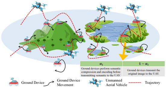
Figure 1.
A multi-UAV-assisted semantic communication network for image transmission tasks.
Assume that each device i collects several images containing environmental information, with a total of bits. Among them, a proportion of the images are semantically encoded and compressed to a depth of by device i and then transmitted to the associated UAV j where the images are semantically decoded and restored to their original form. Correspondingly, the remaining proportion of the images is directly transmitted to UAV j without any processing. The task offloading ratio satisfies , where indicates that all images from device i undergo semantic encoding with no direct transmission of the original images, and means that none of the images from device i are processed and that they are all directly transmitted. The value of is determined based on the configuration of the compressible convolutional module in the semantic communication system. The UAVs have no starting or ending positions and only need to complete the reception of all data within the flight time T.
Upon completing reception, UAVs perform semantic-based image recovery. Ground devices, affected by environmental interference, adjust their positions following a Gaussian–Markov mobility model. We assume LoS channels with interference exist between devices and UAVs. The UAVs are modeled as medium-sized platforms with sufficient embedded computing and storage resources that are capable of concurrent multi-task processing and temporary data retention. This assumption is justified by the reduced data volume of semantic communication and the manageable computational demands of semantic encoding for modern processors, allowing the study to focus on the joint optimization of offloading and resource allocation under user mobility.
2.1. The Mobility Model of Ground Devices
The study is carried out in a three-dimensional Cartesian coordinate system with all measurements in meters. The height of each ground device i is 0, and its horizontal position coordinates at a certain time are . To facilitate problem handling, a time descretization method can be adopted, dividing the system operation time T into N equal-length time slots, each with a duration of . Through this transformation, the horizontal position of ground device i in a specific time slot n can be represented as , where .
At , the system has not yet entered the operation time, the ground devices are randomly distributed, and the position of device i is defined as . During the system operation time, the movement of each device i follows a Gaussian–Markov random mobility model. In time slot n, its speed and direction are calculated as
where and represent the speed of device i in time slot n and , respectively, while and represent the direction of device i in time slot n and , respectively. The parameters denote the memory level, which adjusts the influence of the previous state. represents the average speed, and all ground devices share the same average speed. represents the average direction of device i, and each ground device has a different average direction. and are two independent Gaussian distributions, following different mean–square pairs and .
Based on the formulas for speed and direction , the position of device i in time slot n is given as
2.2. Channel Model
All UAVs fly at a constant altitude H, and the horizontal position of UAV j in time slot n is . Each UAV maintains a constant speed within every time slot. The height of device i is 0, and its horizontal position in time slot n is . Therefore, the distance between UAV j and device i in time slot n is given by
Assuming that the communication channel between ground device i and UAV j is dominated by the Line of Sight (LoS) link, we adopt the free-space propagation model. The channel power gain can be expressed as
where represents the channel power gain at a reference distance of 1 m.
Assume that within each time slot, a UAV can serve at most one device, and a device can be served by at most one UAV across all time slots. A set of UAV–device association variables is introduced to represent the association between UAV j and device i in different time slots. is a binary variable, where indicates that device i establishes a communication connection with UAV j in the n-th time slot, and indicates that no connection is established. The variable satisfies the following constraints:
Assume that all ground devices and UAVs in the region communicate using the same frequency band. There may be cases where multiple devices establish connections with different UAVs within the same time slot, leading to channel interference. The Signal to Interference plus Noise Ratio (SINR) between UAV j and device i in time slot n is given by
where is the noise power at the receiving UAV, represents the transmission power of device i in time slot n, and the term in the denominator represents the channel interference caused by the transmissions of all other devices in time slot n. Therefore, the data transmission rate between UAV j and device i in time slot n can be expressed as
where B represents the channel bandwidth.
2.3. Latency Model
The latency model consists of four parts: semantic encoding latency, transmission latency, semantic decoding latency, and task processing latency.
2.3.1. Semantic Encoding Latency
For any device i, define the computational load of the standard convolutional module when there is no direct transmission of the original image (only semantic transmission) as and the computational load of the compressible convolutional module as , where is the computational load when . Therefore, when the task offloading ratio is , the total computational load for semantic encoding is . Let . For ground device i, the semantic encoding latency model can be expressed as
where is the computational capability of device i.
2.3.2. Transmission Latency
Ground device i needs to transmit both the encoded and compressed semantic data and the unprocessed original images to a UAV j to complete the image transmission task. To ensure that UAV j receives all the data required for the image transmission task from device i, the following constraint must be satisfied
where represents the minimum number of time slots required to complete the transmission, satisfying . We define as the amount of semantic data transmitted over the wireless channel after semantic encoding and compression with depth for the original -bit image. Additionally, for ground device i, the transmission latency model can be expressed as
2.3.3. Semantic Decoding Latency
The semantic decoder has a structure similar to that of the semantic encoder, also consisting of two parts: a standard convolutional module and a compressible convolutional module. For any device i, in the case where there is no direct transmission of the original image, we define the computational load of the compressible convolutional module for semantic decoding as , where is the computational load when , and the computational load of the standard convolutional module for semantic decoding as . Therefore, when the task offloading ratio is , the total computational load for semantic decoding is . Let . For ground device i, the semantic decoding latency model can be expressed as
where the computational capability of all UAVs is .
2.3.4. Task Processing Latency
Ground devices are required to semantically encode and compress selected images, transmit both semantic and raw image data, and enable UAV-side semantic decoding within the UAV’s flight duration. The task processing latency for device i is given by
2.4. Energy Consumption Model
This chapter considers the energy consumption of ground devices and UAVs. The energy consumption model consists of three parts: semantic encoding energy consumption, transmission energy consumption, and semantic decoding energy consumption.
2.4.1. Semantic Encoding Energy Consumption
The semantic encoding energy consumption model for ground device i can be expressed as
where is the energy efficiency factor of the device’s computing chip.
2.4.2. Transmission Energy Consumption
For ground device i, the transmission energy consumption can be expressed as
2.4.3. Semantic Decoding Energy Consumption
The semantic decoding energy consumption model can be expressed as
where is the energy efficiency factor of the computing chip for all UAVs.
2.5. Semantic Evaluation Model
To assess semantic transmission performance, we introduce two key metrics, semantic transmission performance and original image transmission performance, defined as follows.
Based on the SINR obtained in (11), the semantic transmission performance and the original image transmission performance from device i to UAV j in time slot n are respectively given by
where is the logarithmic scale transformation of the SINR, , , and represent the positive constant coefficients of for different , and , , and are the positive constant coefficients of , respectively.
In time slot n, the transmission performance of device i to UAV j can be expressed as
The transmission performance of device i is given by
where . The transmission is completed within time slots, and the impact of any excess transmission can be neglected.
3. Problem Formulation
This paper aims to minimize the maximum task processing latency through joint optimization of UAV–device association, trajectories, transmission power, offloading ratios, and compression depths. To simplify subsequent notation, define the UAV–device association variable set as , the UAV trajectory variable set as , the transmission power set as , the task offloading ratio variable set as , and the compression depth variable set as . The above optimization problem can be formulated as
In problem , constraint (25a) indicates that the transmission performance must be higher than the performance threshold to ensure effective transmission. (25b) and (25c) state that the transmission and computation energy consumption of the ground and UAVs must not exceed the maximum energy threshold. (25d) specifies that the task offloading ratio takes a value between 0 and 1. (25e) requires the compression depth to be selected from a numerically discrete set . (25f) represents the maximum speed constraint of the UAVs. (25g) enforces the collision avoidance distance between UAVs. (25h) represents the transmitted data volume constraint. Since the UAV–device association variables are binary (0 or 1), this constraint is an integer constraint. Additionally, the compression depth selection constraint and the transmitted data volume constraint are non-convex. In summary, it is challenging to solve using conventional convex optimization algorithms.
4. Proposed Algorithm
The original optimization problem is non-convex, so an alternating iterative algorithm can be employed to obtain an approximate optimal solution. Specifically, the problem is decomposed into two subproblems, the UAV-side subproblem and the ground device-side subproblem . Subproblem 1 optimizes given a fixed , while Subproblem 2 optimizes given a fixed . The following subsections will elaborate on the solution approaches for these two subproblems and the overall optimization algorithm.
4.1. Optimization of the UAV-Side Subproblem
Given a fixed set of transmission power, task offloading ratios, and compression depths , Subproblem 1 can be formulated as the following optimization problem
The association variable for the UAV device is discrete, which makes problem nonconvex and unsuitable for conventional convex optimization techniques. To achieve effective solutions, this section models each UAV as an intelligent agent and formulates the problem as a Markov decision process. The Multi-Agent Proximal Policy Optimization (MAPPO) algorithm is used to jointly optimize UAV device associations and UAV trajectories. The key components include state space, global state space, action space, reward function, and state transition probability and are defined as follows.
4.1.1. State Space
Since UAVs can only perceive limited environmental information, the state space represents partial observations from each UAV. For tractability, we transform the optimization of UAV trajectory variables into optimizing flight distance and flight angle . Thus, the state space of UAV j at time slot n is
4.1.2. Global State Space
The global state space s aggregates all agents’ states across N time slots. At time slot n, is
4.1.3. Action Space
The action of each UAV includes the flight distance, the flight angle, and the association of the UAV with the device per time slot. The action of UAV j at time slot n is
The joint action space for all UAVs at time slot n is
4.1.4. Reward Function
The objective reward is the sum of six sub-rewards
with given by
where represents the reward for the time slot, which encourages faster completion of the transmission tasks. denotes the reward for progress in data transmission, which incentivizes efficient data transmission in each time interval. serves as the transmission performance penalty to ensure high communication quality. acts as the transmission computation energy penalty to prevent energy waste, where . functions as the collision penalty to guarantee UAV flight safety. represents the data transmission volume penalty, promoting efficient transmission while avoiding resource wastage. , , , , , and are all positive coefficients. It is worth noticing that and are positive rewards, while , , , and represent negative constraint-related penalties.
4.1.5. State Transition Probability
The state transition probability refers to the probability of UAVs transitioning to the next state given the current state and action . Since the state changes of UAVs are influenced by multiple factors, the state transition probability cannot be explicitly expressed. Therefore, we do not directly evaluate the state transition probability but instead adopt a multi-agent reinforcement learning approach, allowing UAVs to learn optimal decisions through interaction with the environment. MAPPO can better handle collaboration among multiple UAVs, thereby optimizing task completion efficiency.
4.2. MAPPO Algorithm Training Process
The MAPPO algorithm utilizes an Actor–Critic framework, integrating MARL stability and PPO optimization for efficient multi-agent collaboration. Each agent’s Actor network selects actions based on local observations, while the Critic evaluates global state values to maximize collective rewards. Following the convention of [21], and denote the parameters of the Actor and Critic networks, respectively. The training procedure is as follows.
4.2.1. Data Sampling
Under the current policy , execute the agents to collect trajectory data including state , action , reward , state value estimate , and action probability of the old policy .
4.2.2. Critic Network Update
The mean squared error loss is minimized to improve the Critic network’s accuracy in evaluating global state values. We first compute the advantage using Generalized Advantage Estimation (GAE), which measures the relative quality of current actions compared to the baseline policy, given by
where is the discount factor that balances the importance of current versus future rewards. is the GAE parameter that controls the bias–variance tradeoff. is the temporal difference error. is a small constant that limits the magnitude of policy updates to ensure training stability by preventing the new policy from deviating too far from the old policy. is a clipping function that restricts to the interval , avoiding excessively large policy updates. The advantage function can be used to compute the target value function, which guides the critic network to more accurately evaluate the global state value, which can be formulated as
The update formula for the critic equation is given as
where is the state value estimated by the critic, determined by the network parameters .
4.2.3. Update of the Actor Network
First, set the clipped surrogate objective function as
where is the probability ratio between the current policy and the old policy . is the probability that the current policy is based on the action selected in state . is the probability that the old policy is executing the action in the state .
Second, to encourage exploration, PPO often includes an entropy term in the loss function to diversify the policy distribution and avoid premature convergence to suboptimal policies [22]. The entropy is calculated as
Thus, the final loss function for the actor network is
where is a weighting hyperparameter. The Actor and Critic networks can be updated using the Adam optimizer. The current policy parameter’s is copied to the old policy parameter’s afterwards. Finally, iterate through the above seven steps until the policy converges, meaning the agents learn the optimal policy to maximize the global reward.
The flow of algorithms to solve the subproblem on the UAV side based on MAPPO is shown in Algorithm 1.
| Algorithm 1 MAPPO-Based UAV-Side Subproblem Solving Algorithm |
|
4.3. Ground Device-Side Subproblem Optimization
Given a fixed set of UAV–device associations and trajectories , Subproblem 2 can be formulated as the following optimization problem:
Problem becomes a non-convex optimization problem that resists conventional convex methods due to the discrete nature of compression depth . To address this challenge, we employ the Adaptive Particle Swarm Optimization (APSO) algorithm with dynamic inertia adjustment to jointly optimize power allocation, offloading ratio, and compression depth.
As PSO is fundamentally an unconstrained optimization algorithm, we utilize the penalty function method to transform the main constraints of into penalty function
where , , and represent the coefficients for the objective function and three penalty functions, respectively, all of which are positive values. Three terms in the penalty equation, , , and , are defined as follows:
Based on the aforementioned penalty function, the optimization problem can be reformulated as follows:
The PSO algorithm is suitable for continuous variable optimization problems. However, since the compression depth in optimization problem is a discrete value, we perform continuous processing on . During the PSO process, let the particle’s take continuous real values, . Before each objective function calculation, apply rounding mapping: .
In the APSO algorithm, the dimensions of optimization variables , , and are , I, and I, respectively, resulting in a search space dimension of . For particle q at iteration s, its velocity and position can be expressed as
The fitness function of the APSO algorithm is given by
Therefore, as introduced in [21], the particle inertia weight is given by
where and represent the given maximum and minimum values of particle inertia weight, respectively, and represent the global minimum fitness and global average fitness of the particle swarm at the s-th iteration, respectively, and N is the number of particles. Thus, the particle velocity and position update equations are as follows:
where and are the individual and global cognitive coefficients, respectively, and are two random number generators that can produce values between 0 and 1, and and are the individual and global best positions, respectively. If , then update ; if , then update .
By dynamically adjusting particle inertia weights, the particle swarm can achieve a balance between global and local search, improving convergence speed and enhancing algorithm robustness. The specific procedure of the APSO-based ground device-side subproblem solving algorithm is shown in Algorithm 2.
| Algorithm 2 APSO-Based Ground Device-Side Subproblem Solving Algorithm |
|
4.4. Alternating Iteration Algorithm
The solution algorithm for problem is summarized as follows: First, initialize all optimization variables, then decompose the optimization problem into two subproblems: the UAV-side subproblem optimizing UAV-device associations and trajectories and the ground device-side subproblem optimizing transmission power, task offloading ratios, and semantic compression depths. Subsequently, solve these subproblems using MAPPO and APSO algorithms, respectively. During optimization, variables of the current subproblem are optimized while treating variables from the other subproblem as fixed inputs. Alternate between optimizing these two subproblems until algorithm convergence. The multi-UAV dynamic computation offloading and resource allocation algorithm for minimizing maximum task processing delay is presented in Algorithm 3.
| Algorithm 3 Multi-UAV Dynamic Computation Offloading and Resource Allocation Algorithm for Minimizing Maximum Task Processing Delay |
|
5. Simulation Results and Analysis
5.1. Parameter Settings and Baseline Algorithms
This section analyzes the performance of the proposed algorithm through numerical simulations. Consider a 4 km × 4 km two-dimensional area with I ground devices moving randomly in each time slot. UAVs fly at a constant altitude of m. Other simulation parameters and their corresponding values are summarized in Table 1.

Table 1.
Simulation Parameter Settings.
To demonstrate the superior performance of the proposed algorithm, this section compares it with three baseline algorithms: the BPSO algorithm, the MAPPO-PSO algorithm, the and MADDPG-APSO algorithm.
5.1.1. BPSO Algorithm
The optimization variables are divided into UAV-side variables and ground device-side variables . In each iteration, the ground devices perform one PSO-based optimization, while the UAV layer performs PSO-based optimization in each time slot. The optimization results from both layers serve as input information for each other’s optimization process, forming an alternating iterative solution approach.
5.1.2. MAPPO-PSO Algorithm
Replaces the APSO in our proposed algorithm with standard PSO.
5.1.3. MADDPG-APSO Algorithm
Substitutes the MAPPO in our proposed algorithm with MADDPG.
5.2. Feasibility Analysis
Figure 2 shows the transmission performance distribution of all devices under the proposed delay minimization algorithm. The results confirm that the algorithm ensures all devices meet the minimum threshold , with over 50% achieving . This validates the algorithm’s effectiveness in reliable UAV offloading and resource allocation.
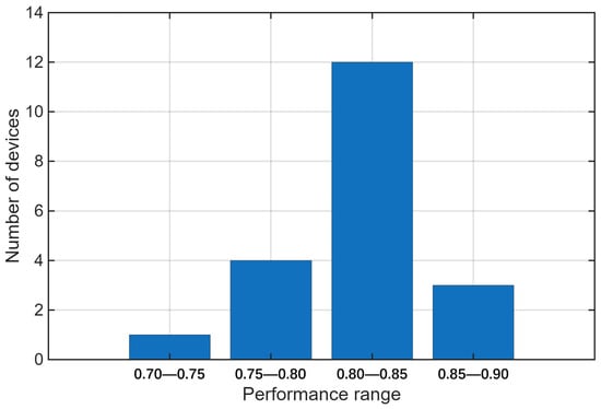
Figure 2.
Transmission performance distribution of devices.
Figure 3 compares the convergence of four algorithms in reducing maximum task processing latency. All algorithms decrease energy consumption and stabilize over iterations, with the proposed MAPPO-APSO achieving the fastest convergence and lowest delay—outperforming others by 2.4%, 4.3%, and 10.8%.
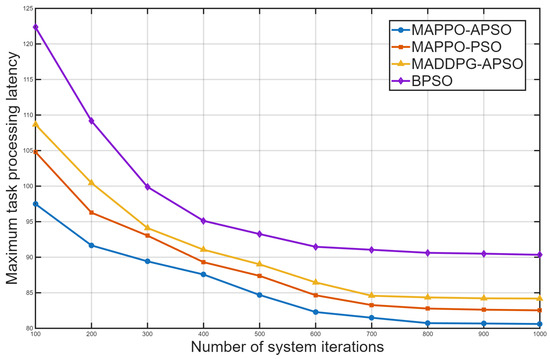
Figure 3.
Convergence of algorithms in reducing latency.
The alternating and asynchronous feature of the proposed MAPPO-APSO method requires primary focus on the convergence of these two algorithms individually. Figure 4 and Figure 5 show the convergence of MAPPO and APSO algorithms. MAPPO’s reward grows rapidly in 600 iterations before stabilizing and converges in 2000 iterations, proving effective for UAV associations and trajectories. APSO converges faster in 100 iterations, optimizing power, offloading, and compression. The observed discrepancy in convergence iterations stems from the fundamental roles of each algorithm: MAPPO learns a high-dimensional policy over many steps, while APSO efficiently solves sub-problems within a well-defined, lower-dimensional search space during each policy iteration. The convergence of the MAPPO and APSO algorithms ensures that the overall MAPPO-APSO system achieves optimal performance.
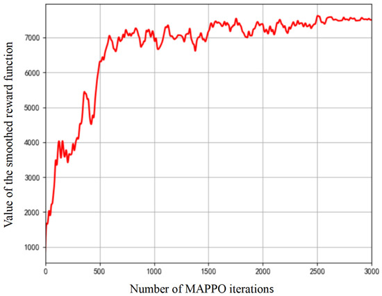
Figure 4.
Convergence of MAPPO algorithm.
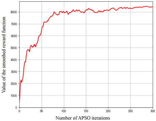
Figure 5.
Convergence of APSO algorithm.
5.3. Task Processing Latency Analysis
Figure 6 compares four algorithms’ performance on maximum task processing latency as ground device numbers vary, with the proposed MAPPO-APSO showing optimal performance. While all algorithms demonstrate comparable low-latency performance with limited ground devices except for the consistently underperforming BPSO, their divergence becomes markedly apparent as device density increases. The proposed MAPPO-APSO maintains superior scalability where competing algorithms MAPPO-PSO and MADDPG-APSO begin to exhibit significant performance degradation. MAPPO-APSO achieves maximum latency reductions of 3.1%, 7.5%, and 20.7% versus competitors, owing to APSO’s adaptive weights and MAPPO’s policy stability.
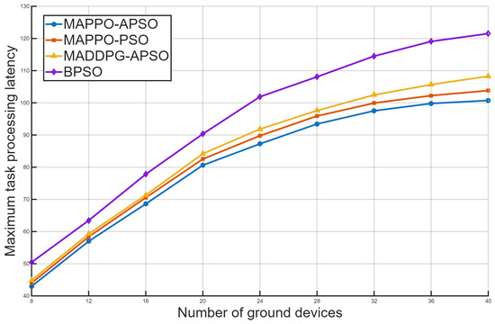
Figure 6.
Comparison of maximum latency among four algorithms with varying ground devices.
5.4. System Energy Consumption Analysis
The transmission and computation energy consumption trends mirror latency patterns, rising with device quantities. Figure 7 shows that the proposed MAPPO-APSO algorithm has superior energy efficiency, particularly in high-density scenarios where computational/transmission burdens intensify. Compared to alternatives, it reduces energy consumption by 6.1%, 9.2%, and 16.1%, respectively. This advantage stems from effective coordination of UAV trajectories and resource allocation, demonstrating MAPPO-APSO’s robustness in complex environments with moving ground devices. The combined approach optimally balances computation offloading and energy consumption in multi-UAV systems.
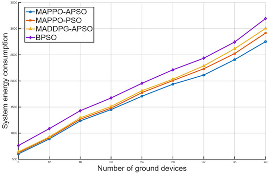
Figure 7.
Comparison of system energy consumption among four algorithms with varying ground devices.
5.5. Discussion and Future Work
In summary, the proposed MAPPO-APSO algorithm in this paper combines the advantages of multi-agent reinforcement learning and adaptive particle swarm optimization, effectively coordinating resources between ground devices and UAVs in complex environments. For multi-UAV semantic communication networks with randomly moving ground devices, this algorithm provides an efficient dynamic computation offloading and resource allocation strategy.
Several promising directions for future work merit further investigation. In our framework, semantic depth presents a key trade-off: deeper extraction reduces transmission latency via higher compression but increases computational overhead and risks information loss, whereas shallower extraction improves reconstruction fidelity at the cost of higher transmission latency. Our proposed algorithm primarily optimizes the resource allocation for a fixed semantic model. The exploration of the optimal operating point on this trade-off curve for different application requirements constitutes a vital direction for our future work.
The combination of MAPPO and APSO inherently demands greater computational resources during the training phase compared to conventional optimization methods. The proposed method can achieve optimal performance and enable intelligent decision-making in complex, dynamic environments, though challenges remain for real-time training and applications with stringent latency requirements, such as disaster response. Meanwhile, a comprehensive comparison against a broader range of state-of-the-art algorithms is identified as a primary objective in order to validate the performance and competitiveness of the proposed method.
Furthermore, integrating federated learning will be a key priority in future work to enhance user privacy during collaborative model training. Considerations about the feasibility of the learning framework will be a central focus of our future work to handle unrealistic simulation assumptions and limited model generalization. Finally, research will also extend to environments with heterogeneous devices possessing varying capabilities, which will necessitate more dynamic resource allocation strategies and pave the way for developing lightweight model architectures for stringent real-time systems.
6. Conclusions
This paper has presented an integrated optimization framework for multi-UAV semantic communication networks with mobile ground devices, addressing the critical challenges of dynamic computation offloading and resource allocation in mobility-aware scenarios. The proposed MAPPO-APSO co-optimization algorithm effectively coordinates transmission power control, UAV–device associations, trajectory planning, and semantic compression through a novel alternating optimization architecture. By decomposing the complex joint optimization problem into complementary subproblems solved via multi-agent reinforcement learning and adaptive swarm intelligence, our approach demonstrates significant improvements over conventional methods. Experimental results confirm the framework’s ability to maintain transmission quality while substantially reducing both processing delay and energy consumption. Compared to existing baseline algorithms, the proposed solution achieves substantial performance gains, including a 16.1% energy saving that directly translates to extended UAV flight time, alongside a 20.7% reduction in latency that accelerates mission completion, particularly excelling in high-density device scenarios.
Author Contributions
Conceptualization, W.H. and Y.D.; Methodology, W.H. and Y.D.; Software, W.H.; Validation, Y.G.; Formal analysis, Y.G.; Investigation, Y.G.; Resources, J.H. and X.Z.; Writing—original draft, W.H.; Writing—review & editing, Y.D., Y.G. and X.Z.; Visualization, W.H.; Supervision, Y.D. and J.H.; Project administration, J.H. All authors have read and agreed to the published version of the manuscript.
Funding
This research received no external funding.
Data Availability Statement
The data presented in this study are available on request from the corresponding author.
Conflicts of Interest
The authors declare no conflict of interest.
References
- Li, W.; Hu, Z.; Wen, X.; Lu, Z.; Zhang, Y. Trade-off between secrecy rate and energy consumption in a secure UAV-MEC system. In Proceedings of the 2022 IEEE/CIC International Conference on Communications in China (ICCC), Foshan, China, 11–13 August 2022; pp. 862–867. [Google Scholar]
- Gu, X.; Zhang, G.; Wang, M.; Duan, W.; Wen, M.; Ho, P.H. UAV-aided energy-efficient edge computing networks: Security offloading optimization. IEEE Internet Things J. 2022, 9, 4245–4258. [Google Scholar] [CrossRef]
- Dong, A.; Hu, Y.; Mei, Z.; Feng, K. Joint task offloading and resource allocation optimisation for UAV-assisted edge computing. In Proceedings of the 2024 6th International Conference on Data-driven Optimization of Complex Systems (DOCS), Hangzhou, China, 16–18 August 2024; pp. 607–612. [Google Scholar]
- Du, Y.; Wang, K.; Yang, K.; Zhang, G. Energy-efficient resource allocation in UAV based MEC system for IoT devices. In Proceedings of the 2018 IEEE Global Communications Conference (GLOBECOM), Abu Dhabi, United Arab Emirates, 9–13 December 2018; pp. 1–6. [Google Scholar]
- Wang, J.; Sun, H. Joint resource allocation and trajectory optimization for computation offloading in UAV-enabled mobile edge computing. In Proceedings of the 2024 6th International Conference on Communications, Information System and Computer Engineering (CISCE), Guangzhou, China, 10–12 May 2024; pp. 302–307. [Google Scholar]
- Xiong, J.; Guo, H.; Liu, J. Task offloading in UAV-aided edge computing: Bit allocation and trajectory optimization. IEEE Commun. Lett. 2019, 23, 538–541. [Google Scholar] [CrossRef]
- Xu, J.; Ai, B.; Chen, L.; Cui, Y.; Wang, N. Deep reinforcement learning for computation and communication resource allocation in multiaccess MEC assisted railway IoT networks. IEEE Trans. Intell. Transp. Syst. 2022, 23, 23797–23808. [Google Scholar] [CrossRef]
- Zhang, X.; Zhong, Y.; Liu, P.; Zhou, F.; Wang, Y. Resource allocation for a UAV-enabled mobile-edge computing system: Computation efficiency maximization. IEEE Access 2019, 7, 113345–113354. [Google Scholar] [CrossRef]
- Yan, L.; Qin, Z.; Zhang, R.; Li, Y.; Li, G.Y. Resource allocation for text semantic communications. IEEE Wirel. Commun. Lett. 2022, 11, 1394–1398. [Google Scholar] [CrossRef]
- Liu, C.; Guo, C.; Yang, Y.; Jiang, N. Adaptable semantic compression and resource allocation for task-oriented communications. IEEE Trans. Cogn. Commun. Netw. 2024, 10, 769–782. [Google Scholar] [CrossRef]
- Wang, L.; Wu, W.; Zhou, F.; Yang, Z.; Qin, Z.; Wu, Q. Adaptive resource allocation for semantic communication networks. IEEE Trans. Commun. 2024, 72, 6900–6916. [Google Scholar] [CrossRef]
- Ding, G.; Liu, S.; Yuan, J.; Yu, G. Joint URLLC traffic scheduling and resource allocation for semantic communication systems. IEEE Trans. Wirel. Commun. 2024, 23, 7278–7290. [Google Scholar] [CrossRef]
- Ding, S.; Ren, C.; Shang, B.; Xu, L.; Fang, H.; Guo, H. Task Execution Strategy for Low-Altitude Economy Based on Cooperative Semantic Multiplexing and Sharing. Xi’an University of Posts and Telecommunications. Available online: https://link.cnki.net/urlid/61.1493.tn.20250108.1648.002 (accessed on 10 January 2025).
- Sun, X.; Chen, J.; Guo, C. Semantic-driven computation offloading and resource allocation for UAV-assisted monitoring system in vehicular networks. In Proceedings of the IECON 2022—48th Annual Conference of the IEEE Industrial Electronics Society, Brussels, Belgium, 17–20 October 2022; pp. 1–6. [Google Scholar]
- Hu, H.; Zhu, X.; Zhou, F.; Wu, W.; Hu, R.Q. Semantic-oriented resource allocation for multi-modal UAV semantic communication networks. In Proceedings of the GLOBECOM 2023—2023 IEEE Global Communications Conference, Kuala Lumpur, Malaysia, 4–8 December 2023; pp. 7213–7218. [Google Scholar]
- Zheng, G.; Ni, Q.; Navaie, K.; Pervaiz, H.; Min, G.; Kaushik, A.; Zarakovitis, C. Mobility-Aware Split-Federated With Transfer Learning for Vehicular Semantic Communication Networks. IEEE Internet Things J. 2024, 11, 17237–17248. [Google Scholar] [CrossRef]
- Pugliese, C. Unveiling Urban and Human Mobility Dynamics through Semantic Trajectory Summarization. In Proceedings of the 2024 25th IEEE International Conference on Mobile Data Management, Brussels, Belgium, 24–27 June 2024; pp. 259–261. [Google Scholar]
- Xu, J.; Solmaz, G.; Rahmatizadeh, R.; Turgut, D.; Boloni, L. Internet of things applications: Animal monitoring with unmanned aerial vehicle. arXiv 2016, arXiv:1610.05287. [Google Scholar] [CrossRef]
- Liu, Q.; Shi, L.; Sun, L.; Li, J.; Ding, M.; Shu, F. Path planning for UAV-mounted mobile edge computing with deep reinforcement learning. IEEE Trans. Veh. Technol. 2020, 69, 5723–5728. [Google Scholar] [CrossRef]
- Miuccio, L.; Riolo, S.; Samarakoon, S.; Bennis, M.; Panno, D. On Learning Generalized Wireless MAC Communication Protocols via a Feasible Multi-Agent Reinforcement Learning Framework. IEEE Trans. Mach. Learn. Commun. Netw. 2024, 2, 298–317. [Google Scholar] [CrossRef]
- Yu, C.; Velu, A.; Vinitsky, E.; Gao, J.; Wang, Y.; Bayen, A.; Wu, Y. The surprising effectiveness of PPO in cooperative multi-agent games. IEEE Trans. Veh. Technol. 2022, 70, 123–135. [Google Scholar]
- Shi, Y.; Eberhart, R.C. Empirical study of particle swarm optimization. In Proceedings of the Congress on Evolutionary Computation, Washington, DC, USA, 6–9 July 1999; pp. 1945–1950. [Google Scholar]
Disclaimer/Publisher’s Note: The statements, opinions and data contained in all publications are solely those of the individual author(s) and contributor(s) and not of MDPI and/or the editor(s). MDPI and/or the editor(s) disclaim responsibility for any injury to people or property resulting from any ideas, methods, instructions or products referred to in the content. |
© 2025 by the authors. Licensee MDPI, Basel, Switzerland. This article is an open access article distributed under the terms and conditions of the Creative Commons Attribution (CC BY) license (https://creativecommons.org/licenses/by/4.0/).