Abstract
Radio frequency (RF)-based wireless systems are broadly used in communication systems such as mobile networks, satellite links, and monitoring applications. These systems offer outstanding advantages over wired systems, particularly in terms of ease of installation. However, researchers are looking for safer alternatives as a result of worries about possible health problems connected to high-frequency radiofrequency transmission. Using the visible light spectrum is one promising approach; three cutting-edge technologies are emerging in this regard: Optical Camera Communication (OCC), Light Fidelity (Li-Fi), and Visible Light Communication (VLC). In this paper, we propose a Multiple-Input Multiple-Output (MIMO) modulation technology for Internet of Things (IoT) applications, utilizing an LED array and time-domain on-off keying (OOK). The proposed system is compatible with both rolling shutter and global shutter cameras, including commercially available models such as CCTV, webcams, and smart cameras, commonly deployed in buildings and industrial environments. Despite the compact size of the LED array, we demonstrate that, by optimizing parameters such as exposure time, camera focal length, and channel coding, our system can achieve up to 20 communication links over a 20 m distance with low bit error rate.
1. Introduction
The IoT system is now integrated into numerous aspects of human life, such as smart homes, e-health, and smart cities [1]. IoT systems enable devices to connect seamlessly to the internet using communication protocols designed for data transmission [2]. These systems encompass physical devices, microcontroller units (MCUs), animals, and even humans, facilitating automatic communication and network connectivity without direct human intervention. With the growth of Industry 4.0, the IoT plays a crucial role in enabling rapid interaction between people and their surroundings. However, most IoT technologies, including LoRa, ZigBee, Bluetooth, and Wi-Fi rely on RF systems, which raises concerns about potential health risks [3]. It is most critical in special environments, such as schools, hospitals, and nursing homes, where weak populations—including children, elderly individuals, and patients—are present. Because of these health issues, many researchers are actively looking for alternative technologies to replace RF–based communication in applications. One promising alternative is use of the light spectrum for information transmission, with three leading technologies emerging: VLC, Li-Fi, and OCC. Although VLC/Li-Fi rely on photodiodes (PDs) to detect LED light intensity, OCC deploys image sensors as receivers. Among the available camera types in the market, global shutter cameras and rolling shutter cameras are broadly used for OCC systems [4]. Compared to RF technologies, OWC offers some advantages:
- Safety: Unlike RF waves, visible light waves do not pose health risks to humans [5]. The RF waveform, however, can have harmful effects and may also cause system performance issues due to electromagnetic interference.
- Higher bandwidth: the bandwidth of the light waveform is over 1000 times greater than that of RF, making it more efficient for data transmission.
- Secure and efficient transmission: visible light waves offer high safety and more efficient communication.
Recognizing the potential of OWC, many companies have invested significant resources in research and development to enhance this technology. The IEEE 802.15.7-2011 standard [6] presented OWC, considering a simple method in 2011, primarily focusing on Visible Light Communication (VLC). After that, the IEEE 802.15.7-2018 standard [7] was proposed as an updated version, incorporating additional advancements in OWC. The IEEE 802.15.7a-2024 standard follows enhancements to the physical (PHY) layer [4]. Due to advancements in manufacturing technology, LEDs offer several benefits, such as a long lifespan, low power consumption, and availability in various sizes and operational modes compared to conventional light. They are, therefore, one candidate for a future lighting system instead of normal light in the market. Moreover, one key feature that makes LEDs ideal for OWC systems is their ability to switch on and off speedily [8], allowing high-speed data communication. At present, RF systems dominate various applications, including communication networks, monitoring systems, and radar technology. Nevertheless, RF signals produce electromagnetic interference (EMI) [9], which has been connected to possible health hazards, especially with regard to brain function [10]. In contrast, OWC technologies are emerging as a good, EMI–free substitute to RF–based communication systems [11]. In VLC and Li-Fi systems, PDs detect LED intensity by interpreting the rapid switching of LEDs between on and off states [12]. Research efforts [13,14] have demonstrated ultra-high-speed pulse density modulation with highly efficient spectral properties using photodiodes. Additionally, studies [15,16] have implemented MIMO techniques to enhance the data rate through multi-channel VLC/Li-Fi systems. However, VLC and Li-Fi systems face limitations due to their reliance on photodiodes as detectors. The communication range is quite short, making it more suitable for indoor applications. In outdoor environments, channel distortions hinder the photodiode’s ability to effectively receive LED signals. However, OCC, which utilizes image sensors as receivers, can operate over significantly longer distances up to 150 m [17]. Research [18] has highlighted the impact of different types of cameras on the OCC system. In global shutter cameras, factors such as frame rate in the receiver side and packet rate in the transmitter side must be cautiously managed according to Nyquist’s theorem. When it comes to rolling shutter cameras, we need to take into account both the rolling shutter speed and the frame rate. It is also important to control several parameters, such as exposure time, camera focal length, and signal-to-noise ratio (SNR), in order to increase the communication range. Currently, Li-Fi technology can achieve a maximum transmission distance of approximately 10 m by incorporating photodiode lenses [19].
Optical Camera Communication (OCC) techniques enable the easy implementation of Multiple-Input Multiple-Output (MIMO) systems, allowing simultaneous communication with multiple LEDs using a single image sensor. Though, achieving MIMO with PDs is challenging, especially when handling a large number of connections. A commonly used algorithm in OCC systems is the Region of Interest (RoI) algorithm, which helps detect multiple objects. Based on the rolling shutter effect, ref. [20] presented a Camera On-Off Keying (C-OOK) to design the high-speed system. However, this approach has limitations, including a limited communication range and reduced performance. In [21,22], authors proposed RS-OFDM, a scheme that combines Orthogonal Frequency Division Multiplexing (OFDM) with the rolling shutter camera, to enhance data rates in OCC systems. In [23], a color intensity modulation-MIMO technology was introduced, achieving data using a global shutter camera operating at 330 frames per second with a maximum distance of 1.4 m. However, the global shutter camera is expensive and not broadly available. Moreover, applying colors for signal transmission introduces challenges compared to the On-Off Keying (OOK) scheme, such as a limited transmission range and higher bit error rates. To address these issues, the authors in [24,25,26] developed a MIMO scheme using an LED array. The Discrete Hartley Transform (DHT) IV algorithm is a mathematical transformation like the Discrete Fourier Transform. It is applied for image and video processing, and computer vision with low latency. While this method mitigates flicker effects, it has several disadvantages, including a short communication range (1.4 m) and a lack of rotational support, which are critical for OCC–based IoT systems.
In this study, we suggest a monitoring system utilizing an OCC framework that integrates RoI signaling and MIMO techniques considering an LED array. This OCC scheme is compatible with both rolling shutter cameras and global shutter cameras, and it is particularly suitable for deployment with Closed-Circuit Television (CCTV) cameras, which are widely available. The system’s adaptability to existing CCTV infrastructure enhances its applicability in environmental monitoring. By applying deep learning to a 2D MIMO-OOK scheme, we achieve a communication range of up to 20 m with 20 links simultaneously.
The remainder of study is presented as follows: Section 2 highlights the contributions of the proposed approach. Section 3 presents the system architecture of deep learning-based Optical Camera Communication. In Section 4, implementation results are shown over a long distance and with a low data rate. Finally, Section 5 concludes this study.
2. Contributions
In this study, the authors recommend an Optical Camera Communication (OCC) system for IoT applications using MIMO technology with an LED matrix. This approach is well-suited with most commercial cameras existing on the market. The key advantages of the proposed scheme are outlined below:
- Compatibility with Various Camera Types: the system supports most commercial cameras existing on the market by appropriately adjusting the exposure time.
- Rotation Support: The scheme ensures full 360-degree rotation support by applying a matrix transpose. By anchor positioning the four corners of the LED matrix, cameras can accurately distinguish and process rotation.
- Frame Rate Variation Handling and Data Merging Algorithm: Frame rate variation is a significant challenge in OCC systems, often leading to packet loss during data decoding at the receiver. While many people assume that a camera’s labeled frame rate (e.g., 30 fps or 60 fps) remains non-changeable, fluctuations can cause synchronization issues between the transmitter and receiver. The system embeds a sequence number (SN) in each sub-packet, which indicates the sequence within the data stream. By adjusting the SN length according to the data packet size, the OCC system can be optimized.
- Missing Packet Detection: To efficiently reconstruct images from consecutive packet transmissions, the system employs an SN within each packet. By comparing SNs across successive images, the receiver can easily identify and compensate for most missing packets.
- Multiple Link Process: By applying deep learning, we can process multiple users at the same time with high speed and over a long distance. With deep learning for object detection and data decoding, we can achieve very good performances (data rate: 15.360 kbps, distance up to 25 m, and 20 links considering a mobile environment).
3. System Architecture
The core principle of OCC technologies is to manipulate the intensity of optical waveforms for data transmission and reception. One of the most widely used for digital communication is the On-Off Keying (OOK), a simple form of amplitude-shift keying that utilizes two signal states—ON and OFF—to represent binary data, with “1” corresponding to ON and “0” to OFF. In this paper, we present a detailed explanation of our proposed 2D MIMO-OOK, designed for monitoring applications using OCC technology. By strategically positioning each LED within the array according to the spatial frame format of the 2D MIMO-OOK, the receiver can efficiently detect and decode data. In Figure 1, we show the 2D MIMO-OOK architecture, with the functionality of its components.
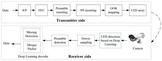
Figure 1.
Optical Camera Communication for IoT system based 2D MIMO-OOK scheme.
3.1. Anchor Detection
Because Region of Interest (RoI) algorithms [27,28] solve complex problems with high accuracy, they are frequently employed for object detection in OCC systems. Object-based and feature-based detection are the two principal methods that these algorithms usually employ [29,30]. The feature-based technique finds likely pixels and groups them to create a return on investment. However, as not every pixel in optical images has strong distinguishing characteristics, this method’s inability to reliably recognize a complete object is a disadvantage. On the other hand, by utilizing structural and shape-based information, the object-based approach provides enhanced RoI detection. Using an RoI technique, we locate anchors at the LED array’s four corners in this study. The receiver can effectively detect these four outermost LEDs using the RoI method because they are always in the ON state. The locations of the other LEDs in the array may be quickly ascertained and decoded if the coordinates of these four reference points are known.
3.2. Start of Frame Addition
The preamble is the start of a symbol frame. It is designed to facilitate synchronization and the start of frame detection. This part serves a crucial role in helping the receiver accurately identify the start of a frame for suitable data decoding. Since the preamble does not carry real data, this length should be carefully considered to optimize OCC efficiency. In our proposed scheme, we define a preamble length of 6 bits, with a Start Frame (SF) part of “011100”.
4. Implementation Results
4.1. SNR Measurement
The SNR parameters were calculated and measured to analyze the relationship among range, power of transmitter, and exposure time. Through adjusting exposure time, we can improve the distance and SNR of a signal. In the experimental setup, multiple measurements were conducted at varying communication distances, ranging from 5 to 20 m. As shown in Figure 2, the transmitter side contained an 8 × 8 LED matrix, while the receiver side included a rolling shutter camera (Point Grey camera). Moreover, during the measurements, the camera’s exposure time was varied between 150 μs and 300 μs to evaluate its impact on communication performance at different distances (5, 10, 15, and 20 m).
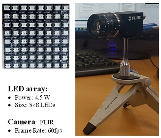
Figure 2.
Devices for SNR measurement.
SNR measurements were conducted at distances of 20, 15, 10, and 5 m as shown in Figure 3. The SNR was considered based on the two operating states of the LED. When the LED is ON, the SNR reflects the signal power emitted by the LED. Equally, when the LED is OFF, the SNR represents the background noise level. The SNR (dB) can be determined as in Equation (1):
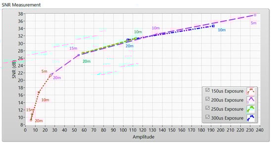
Figure 3.
SNR measurement considering different distances and exposure times.
From that, A denotes the signal power from the LED, corresponding to the pixel amplitudes collected when the LED is “on”. B denotes the background noise, measured as the pixel amplitude when the LED is “off”. The variable n indicates the number of samples collected. At short distances, the pixel amplitudes are higher due to stronger signal strength, whereas at greater distances, the amplitudes decrease as the signal weakens.
4.2. 2D MIMO-OOK Technology
Figure 4 illustrates the frame structure of the 2D MIMO-OOK system. The four outermost corners of the LED matrix serve as anchor points for corner recognition. Using their coordinates, the positions of all LEDs in the array can be determined through perspective transformation. In this system, an 8 × 8 LED array is applied, with 40 LEDs allocated for information communication. As illustrated in Figure 4, the four corner LEDs act as anchors, with anchor 3 specifically enhancing rotational robustness at the receiver. Anchor 4 was the special anchor for the support rotation effect. With anchors 1–3, we used only a single LED with ON status, and three LEDs with OFF status. However, with anchor 4, we used four LEDs with ON status. The special corner is for the support rotation effect. Moreover, 16 LEDs at the anchor positions function as training signals, enabling the camera to distinguish between the ON and OFF states. Each frame includes a preamble to help the receiver identify the frame’s starting point. To accommodate variations in frame rate, the SN is incorporated in each packet. This SN helps synchronize the packet transmission rate with the camera’s frame capture rate, and its length is adjusted accordingly based on this relationship. After identifying the objects, the OCC signal was designated after the LED region using down-sampling. The 2D MIMO-OOK data was then distinguished by extracting the central intensity of each LED by YOLOv11 [31,32,33,34]. A dataset of 10,000 samples, including both preamble and payload segments, was collected using global shutter and rolling shutter cameras at varying distances (ranging from 1 to 20 m) and speeds. To prevent overfitting, we applied a simple deep learning neural network as revealed in Figure 5. The accuracy of this model achieved more than 95%. Once the preamble was detected, we were able to accurately decode the 2D-MIMO signals, enhancing the performance of the OCC system in mobile scenarios compared to traditional methods. It was observed that using six or more hidden layers could lead to overfitting, reducing the accuracy on test data. In addition, we applied a deep learning model for decoding data. By applying DL for detecting the preamble position and threshold value between bits “0” and “1” as shown in Figure 5, we improved OCC performance. For deep learning based on the decoder, we used a basic deep learning neural network model with two hidden layers to avoid overfitting the model. To reduce the interference between two LEDs in the LED array, the distance between two LEDs and the communication distance was considered. Due to the camera process based on the pixel in the image, to clarify multiple LEDs in the array, the distance between each LED needed to be higher than one pixel in the image.
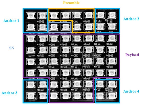
Figure 4.
The spatial frame format in an 8 × 8 LED array.
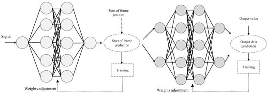
Figure 5.
Deep learning decoder for threshold prediction and preamble detection.
In this study, we conducted multiple deployments of the proposed scheme using a variety of cameras—including webcams, CCTVs, tablets, and a Point Grey camera—to evaluate the impact of frame rate variations. The asynchronous system involves components such as asynchronous decoding, data merging techniques, and missing data detection. The length of the SN is defined based on the overall integration of the system’s operations. Figure 6 displays the quantized intensity profiles of the images across different distances and viewing angles. Figure 7 depicts the experimental setup used to validate the 2D MIMO-OOK system, and Figure 8 presents the results obtained using 20 links. By using a focal length of 35 mm, we achieved 20 links at a 25 m distance with a data rate up to 15 kbps. Focal length refers to the distance between a lens and its focal point, where light rays converge or diverge. It is a fundamental property of lenses that determines both magnification and the angle of view in optical systems, such as cameras and the human eye. To increase the communication distance, we used a higher focal length. The implementation outcomes are provided in Table 1. A deep learning decoder was applied to improve OCC performance. For applications in a mobile environment, YOLOv11 was applied to detect the LED matrix. After receiving data, the camera distinguished the preamble and threshold prediction based on the deep learning model. In this study, we proposed deep learning for a 2D MIMO-OOK for long-range and mobile situations.
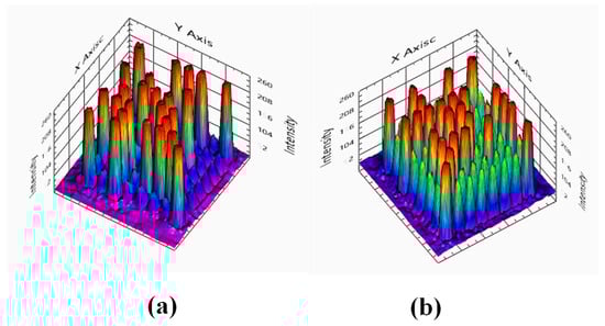
Figure 6.
Quantized intensity profiles of an 8 × 8 LED array with different exposure times and distances: (a) 1 m and 200 µs; (b) 2 m and 400 µs.
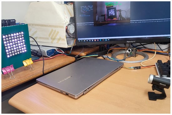
Figure 7.
System setup with single LED matrix.
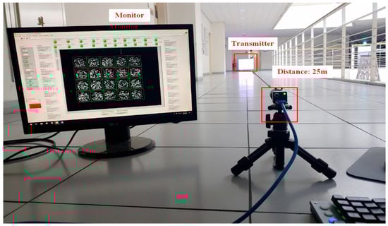
Figure 8.
Rx interface with 10 links.

Table 1.
Characteristic parameters of 2D MIMO-OOK scheme in lab environment.
Figure 6 shows how communication distance and exposure time affect the 8 × 8 LED array intensity in captured images, as well as corresponding SNR values. The colors in Figure 6 represent the intensity levels in the image. High intensity is shown in red color, while low intensity is shown in violet color. Although extending the exposure time can increase the effective communication range, it must be carefully considered. As discussed, the camera behaves similarly to a low-pass filter—meaning that longer exposure times reduce the system’s bandwidth. This occurs because increased exposure time raises the background noise power, potentially degrading overall signal quality.
Figure 9 presents the implementation results using a Point Grey camera across various distances with/without deep learning. The demonstration showed that a deep learning decoder plays a critical role in the performance of the proposed schemes. Even under identical communication distances and noise conditions, the bit error rate (BER) with deep learning had a good performance compared to the non-deep learning decoder. To reduce the BER or extend the communication range, channel coding techniques should be applied to enhance system reliability. Main system parameters are summarized in Table 1. As show in Figure 9, we can see that we can achieve a BER of with a deep learning model considering a processing time of 0.025 s and achieve a BER of without a deep learning model at distance of 8 m considering a processing time of 0.02 s. The deep learning model is, therefore, a good candidate to improve OCC performance. In the future, intelligent multi-modal sensing-communication integration [35,36] will be a feasible path that can facilitate the design of the OCC system and 6G and beyond 6G systems. By applying communication integrated with a sensing model, we may improve the performance of a next-generation communication system. The implementation, which employs a 16 × 16 LED matrix with 20 links and 8 × 8 LED matrix with 10 links considering a mobile environment, successfully achieves communication at a distance of 20 m as demonstrated in the Supplementary Materials.
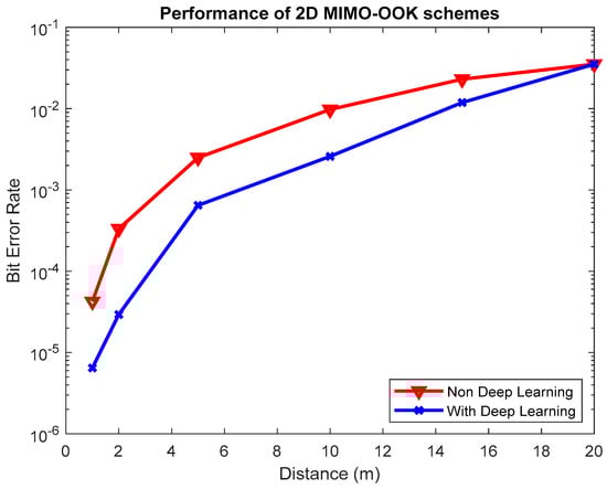
Figure 9.
Bit error rate of proposed scheme for 8 × 8 LED matrix with deep learning and non-deep learning.
5. Conclusions
This paper proposes a monitoring system for Optical Camera Communication (OCC) based on a 2D MIMO-OOK scheme. The system utilizes a custom-designed spatial frame format with an LED array, allowing for rotation support—an essential capability for accurate 2D code recognition. To address frame rate variation and enable the reconstruction of large data packets from multiple images, each transmitted packet includes an SN. SNR measurements were conducted under different distances and exposure times in an indoor environment to examine the interdependence among some key parameters: distance, exposure time, and SNR. While increased exposure time can improve the SNR, this leads to a trade-off with reduced bandwidth, requiring precise calibration. In addition, by applying a deep learning model, our proposed scheme can support a mobile environment with YOLOv11 for LED matrix detection and a low BER with a deep learning decoder considering long distance and multiple users.
Supplementary Materials
The following supporting information can be downloaded at: https://www.mdpi.com/article/10.3390/electronics14153011/s1. The supplementary material video shows the implementation of our proposed scheme at a distance of 20 m with 20 links.
Author Contributions
All authors contributed to this paper: H.N. proposed the idea and implementation methodology; and Y.M.J. supervised the work and provided funding support. All authors have read and agreed to the published version of the manuscript.
Funding
This work was supported by the National Research Foundation of Korea (NRF) grant funded by the Korea government (MSIT) (No.2022R1A2C1007884).
Data Availability Statement
Restrictions apply to the datasets due to the project policy.
Conflicts of Interest
The authors declare no conflicts of interest.
References
- Elijah, O.; Rahman, T.A.; Orikumhi, I.; Leow, C.Y.; Hindia, M.N. An overview of IoT and data analytics in agriculture: Benefits and challenges. IEEE Internet Things J. 2018, 5, 3758–3773. [Google Scholar] [CrossRef]
- Wazid, M.; Das, A.K.; Odelu, V.; Kumar, N.; Conti, M.; Jo, M. Design of secure user authenticated key management protocol for generic IoT networks. IEEE Internet Things J. 2018, 5, 269–282. [Google Scholar] [CrossRef]
- Kim, J.H.; Lee, J.K.; Kim, H.G.; Kim, K.B.; Kim, H.R. Possible effects of radiofrequency electromagnetic field exposure on central nerve system. Biomol. Ther. 2019, 27, 265–275. [Google Scholar] [CrossRef]
- Nguyen, H.; Utama, I.B.K.Y.; Jang, Y.M. Enabling Technologies and New Challenges in IEEE 802.15.7 Optical Camera Communications Standard. IEEE Commun. Mag. 2024, 62, 90–95. [Google Scholar] [CrossRef]
- Nikola, S.; Volker, J.; Yeong Min, J.; John, L.Q. An Overview on High-Speed Optical Wireless/Light Communications. Available online: https://mentor.ieee.org/802.11/dcn/17/11-17-0962-02-00lc-an-overviewon-high-speed-optical-wireless-light-communications.pdf (accessed on 1 February 2019).
- IEEE-SA. IEEE Std 802.15.7-2011; IEEE Standard for Local and Metropolitan Area Networks—Part 15.7: Short-Range Wireless Optical Communication Using Visible Light. IEEE-SA: Piscataway, NJ, USA, 2011.
- IEEE-SA. IEEE Std 802.15.7-2018; IEEE Standard for Local and metropolitan area networks--Part 15.7: Short-Range Optical Wireless Communications. IEEE-SA: Piscataway, NJ, USA, 2018.
- Pathak, P.H.; Feng, X.; Hu, P.; Mohapatra, P. Visible light communication, networking, and sensing: A survey, potential and challenges. IEEE Commun. Surv. Tutor. 2015, 17, 2047–2077. [Google Scholar] [CrossRef]
- Zhang, X.; Xu, K.; Xu, N.; Li, W. Electromagnetic Interference Diagnosis of RF Circuits Based on Near Field Scanning. In Proceedings of the 2023 IEEE 7th International Symposium on Electromagnetic Compatibility (ISEMC), Hangzhou, China, 20–23 October 2023. [Google Scholar]
- Tan, K.S.; Hinberg, I.; Wadhwani, J. Electromagnetic interference in medical devices: Health Canada’s past current perspectives and activities. In Proceedings of the IEEE International Symposium Electromagnetic Compatibility, Montreal, QC, Canada, 13–17 August 2001; pp. 1283–1284. [Google Scholar]
- Ong, Z.; Rachim, V.P.; Chung, W.Y. Novel electromagnetic-interference-free indoor environment monitoring system by mobile camera-image-sensor-based VLC. IEEE Photonics J. 2017, 9, 1–11. [Google Scholar] [CrossRef]
- Haas, H.; Yin, L.; Wang, Y.; Chen, C. What is LiFi? J. Lightwave Technol. 2015, 34, 1533–1544. [Google Scholar] [CrossRef]
- Ali, A.Y.; Zhang, Z.; Zong, B. Pulse position and shape modulation for visible light communication system. In Proceedings of the International Conferences Electromagnetics Advanced Application, Palm Beach, FL, USA, 3–8 August 2014; pp. 546–549. [Google Scholar]
- Videv, S.; Haas, H. Practical space shift keying VLC system. In Proceedings of the IEEE Wireless Communication Networking Conferences, Istanbul, Turkey, 6–9 April 2014; pp. 405–409. [Google Scholar]
- Deng, P.; Kavehrad, M. Real-time software-defined single-carrier QAM MIMO visible light communication system. In Proceedings of the Integrated Communications Navigation and Surveillance (ICNS), Herndon, VA, USA, 19–21 April 2016; pp. 5A3-1–5A3-11. [Google Scholar]
- Cai, H.B.; Zhang, J.; Zhu, Y.J.; Zhang, J.K.; Yang, X. Optimal constellation design for Indoor MIMO visible light communications. IEEE Commun. Lett. 2016, 20, 264–267. [Google Scholar] [CrossRef]
- Nguyen, H.; Jang, Y.M. Experimental Demonstration of Deep Learning-Based HS2PSK-OFDM Scheme for Optical Camera Communication. ICT Express 2025, 2405–9595. [Google Scholar] [CrossRef]
- Nguyen, H.; Jang, Y.M. Survey of next-generation optical wireless communication technologies for 6G and Beyond 6G. ICT Express 2025, 11, 576–589. [Google Scholar] [CrossRef]
- Ayyash, M.; Elgala, H.; Khreishah, A.; Jungnickel, V.; Little, T.; Shao, S.; Rahaim, M.; Schulz, D.; Hilt, J.; Freund, R. Coexistence of WiFi and LiFi toward 5G: Concepts, opportunities, and challenges. IEEE Commun. Mag. 2016, 54, 64–71. [Google Scholar] [CrossRef]
- Nguyen, H.; Tran, D.H.; Jang, Y.M. Design and Implementation of Deep Learning for MIMO C-OOK Scheme-based Optical Camera Communication. In Proceedings of the 2022 13th International Conference on Information and Communication Technology Convergence (ICTC), Jeju Island, Korea, October 2022; pp. 1905–1908. [Google Scholar]
- IEEE Std 802.15.7a-2024; IEEE Standard for Local and Metropolitan Area Networks—Part 15.7: Short-Range Optical Wireless Communications Amendment 1: Higher Rate, Longer Range Optical Camera Communication (OCC). IEEE: New York, NY, USA, 2024.
- Nguyen, H.; Jang, Y.M. Design and Implementation of Rolling Shutter MIMO-OFDM scheme for Optical Camera Communication System. In Proceedings of the 2021 International Conference on Information and Communication Technology Convergence (ICTC), Jeju Island, Korea, 20–22 October 2021. [Google Scholar]
- Huang, W.; Tian, P.; Xu, Z. Design and implementation of a real-time CIM-MIMO optical camera communication system. Opt. Express 2016, 24, 24567–24579. [Google Scholar] [CrossRef] [PubMed]
- Teli, S.R.; Matus, V.; Zvanovec, S.; Perez-Jimenez, R.; Vitek, S.; Ghassemlooy, Z. Optical camera communications for IoT–rolling-shutter based MIMO scheme with grouped LED array transmitter. Sensors 2020, 20, 3361. [Google Scholar] [CrossRef]
- Jung, H.; Kim, S.-M. Experimental Demonstration of 3 × 3 MIMO LED-to-LED Communication Using RGB Colors. Sensors 2021, 21, 4921. [Google Scholar] [CrossRef]
- Teli, S.R.; Zvanovec, S.; Perez-Jimenez, R.; Ghassemlooy, Z. Spatial frequency-based angular behavior of a short-range flicker-free MIMO–OCC link. Appl. Opt. 2020, 59, 10357–10368. [Google Scholar] [CrossRef] [PubMed]
- Lin, H.; Si, J.; Abousleman, G.P. Region-of-interest detection and its application to image segmentation and compression. In Proceedings of the 2007 International Conference on Integration of Knowledge Intensive Multi-Agent Systems, Waltham, MA, USA, 30 April–3 May 2007. [Google Scholar]
- Lin, G.-S.; Tuan, N.-M.; Chen, W.-J. Detecting region of interest for cadastral images in Taiwan. Multimed. Tools Appl. 2017, 76, 25369–25389. [Google Scholar] [CrossRef]
- Lin, G.-S.; Tu, J.-C.; Lin, J.-Y. Keyword Detection Based on RetinaNet and Transfer Learning for Personal Information Protection in Document Images. Appl. Sci. 2021, 11, 9528. [Google Scholar] [CrossRef]
- Cheng, Y.; Yang, P.; Zhang, N.; Hou, J. Edge-Assisted Lightweight Region-of-Interest Extraction and Transmission for Vehicle Perception. In Proceedings of the 2023 IEEE Global Communications Conference, Kuala Lumpur, Malaysia, 4–8 December 2023; pp. 1054–1059. [Google Scholar]
- He, L.-H.; Zhou, Y.-Z.; Liu, L.; Cao, W.; Ma, J.-H. Research on object detection and recognition in remote sensing images based on YOLOv11. Sci. Rep. 2025, 15, 1–25. [Google Scholar] [CrossRef]
- Luo, Y.; Wu, A.; Fu, Q. MAS-YOLOv11: An Improved Underwater Object Detection Algorithm Based on YOLOv11. Sensors 2025, 25, 3433. [Google Scholar] [CrossRef]
- Zhuo, S.; Bai, H.; Jiang, L.; Zhou, X.; Duan, X.; Ma, Y.; Zhou, Z. SCL-YOLOv11: A Lightweight Object Detection Network for Low-Illumination Environments. IEEE Access 2025, 13, 47653–47662. [Google Scholar] [CrossRef]
- Liao, Y.; Li, L.; Xiao, H.; Xu, F.; Shan, B.; Yin, H. YOLO-MECD: Citrus Detection Algorithm Based on YOLOv11. Agronomy 2025, 15, 687. [Google Scholar] [CrossRef]
- Alkhateeb, A.; Jiang, S.; Charan, G. Real-Time Digital Twins: Vision and Research Directions for 6G and Beyond. IEEE Commun. Mag. 2023, 61, 128–134. [Google Scholar] [CrossRef]
- Huang, Z.; Bai, L.; Sun, M.; Cheng, X. A LiDAR-Aided Channel Model for Vehicular Intelligent Sensing-Communication Integration. IEEE Trans. Intell. Transp. Syst. 2024, 25, 20105–20119. [Google Scholar] [CrossRef]
Disclaimer/Publisher’s Note: The statements, opinions and data contained in all publications are solely those of the individual author(s) and contributor(s) and not of MDPI and/or the editor(s). MDPI and/or the editor(s) disclaim responsibility for any injury to people or property resulting from any ideas, methods, instructions or products referred to in the content. |
© 2025 by the authors. Licensee MDPI, Basel, Switzerland. This article is an open access article distributed under the terms and conditions of the Creative Commons Attribution (CC BY) license (https://creativecommons.org/licenses/by/4.0/).