
An Internet of Things—Supervisory Control and Data Acquisition (IoT-SCADA) Architecture for Photovoltaic System Monitoring, Control, and Inspection in Real Time


Abstract
1. Introduction
2. Related Work
- Real-time monitoring and control of a PV system are achieved using Internet of Things architecture. The integration of IoT platforms facilitates the system implementation by providing functions, such as data aggregation, communication security, and data-driven applications.
- The design using two IoT platforms increased the system robustness based on the data redundancy. When one platform shuts down its service by schedule or accident, the other platform can continue to function.
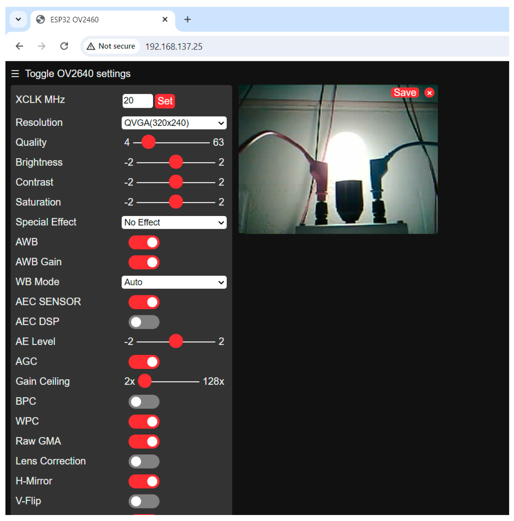
- Images of the load can be accessed on a web server, enabling the visual verification of the load status. Anomalies that might not be detectable through voltage or current sensors alone, such as a burned-out lamp, can be observed and detected. Visual surveillance also provides versatility regarding environmental changes around the lamp and intuitions about the status of multiple lamps.
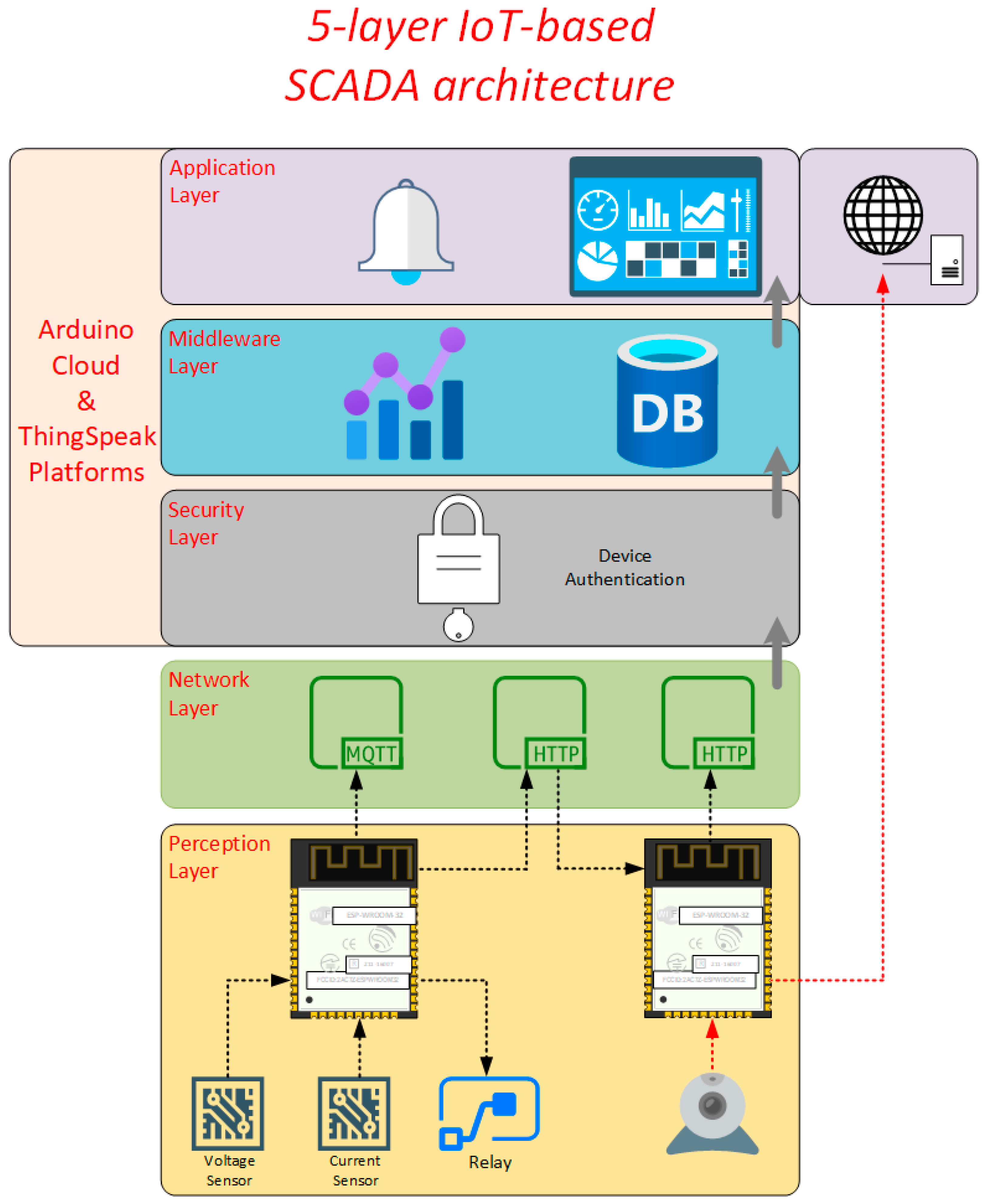
3. System Descriptions
4. SCADA System Components
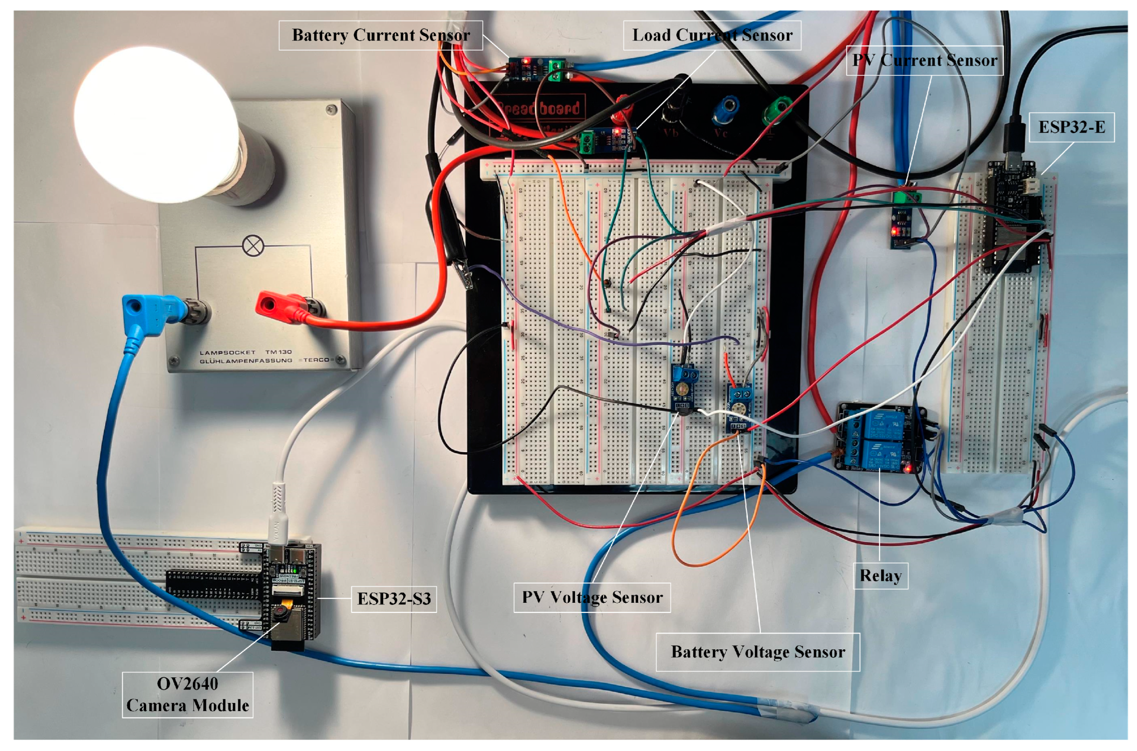
4.1. ESP32-S3 and ESP32-E
4.2. Arduino Cloud
- Device Management: It allows users to manage multiple Arduino boards or third-party devices on one platform with a customized user interface.
- Security: To set up a new device in the platform, a device ID and a secret key are provided to realize the authentication process.
- Cloud Programming: Users can write, compile, and upload codes to the devices from the web browser, instead of installing a local programming IDE environment.
- Remote Control: Widgets that link to pre-defined variables can control the states of these variables.
- Over-the-Air Updates: Users can update the firmware of the devices over the air, without removing the field devices from their deployment place.
- Cloud Services Integration: The Arduino Cloud supports integration with other cloud services, such as Google Cloud, AWS, and IFTTT, allowing for complex and automated workflows.
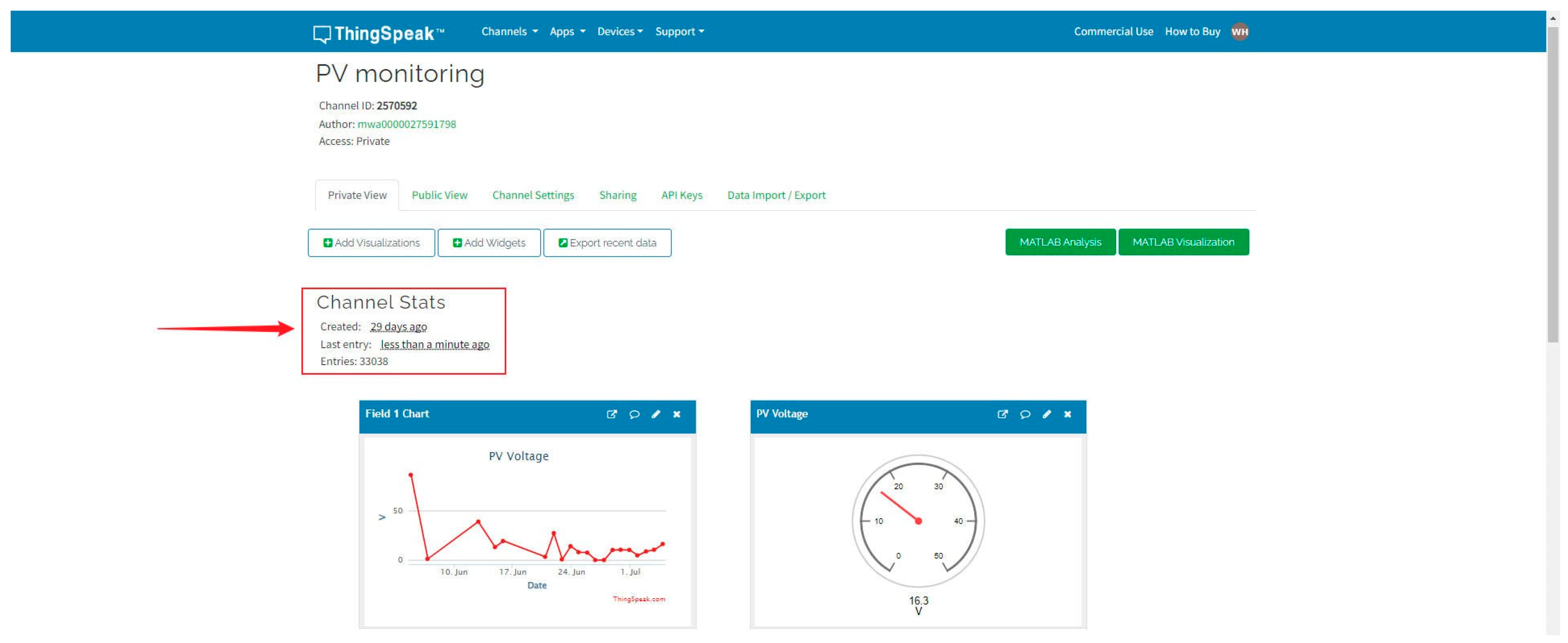
4.3. ThingSpeak
4.4. Voltage Sensor and Current Sensors
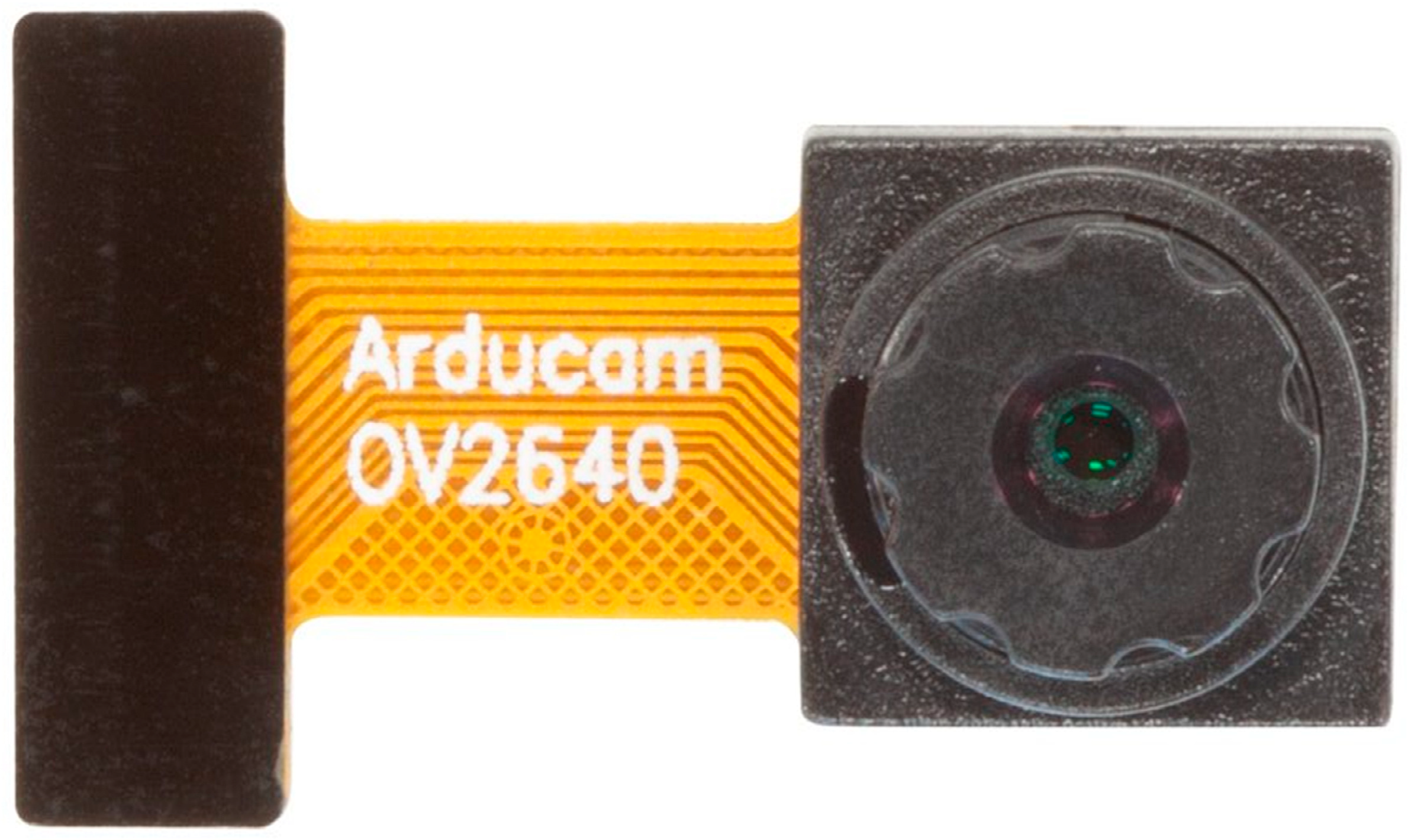
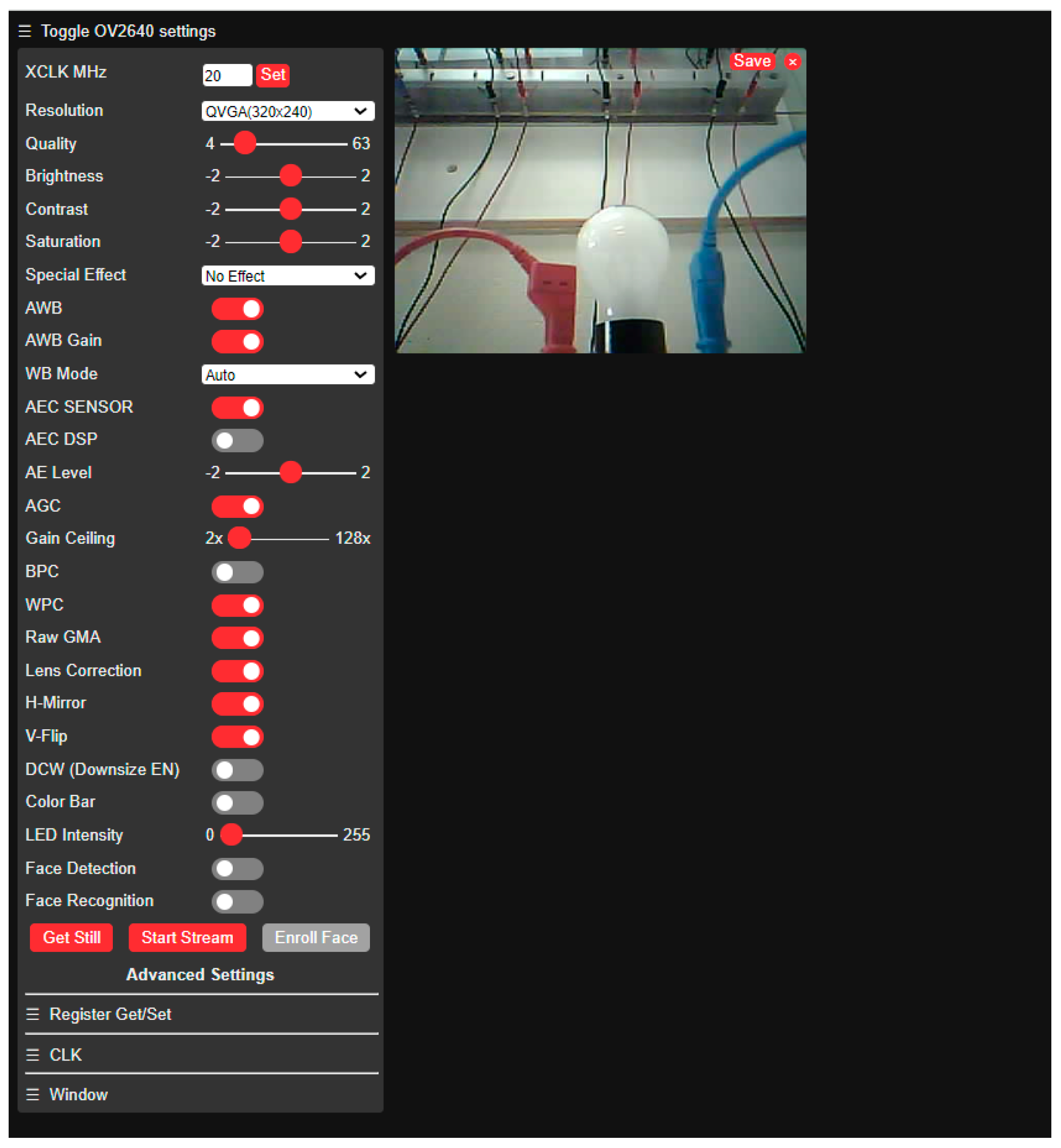
4.5. OV2640 Camera
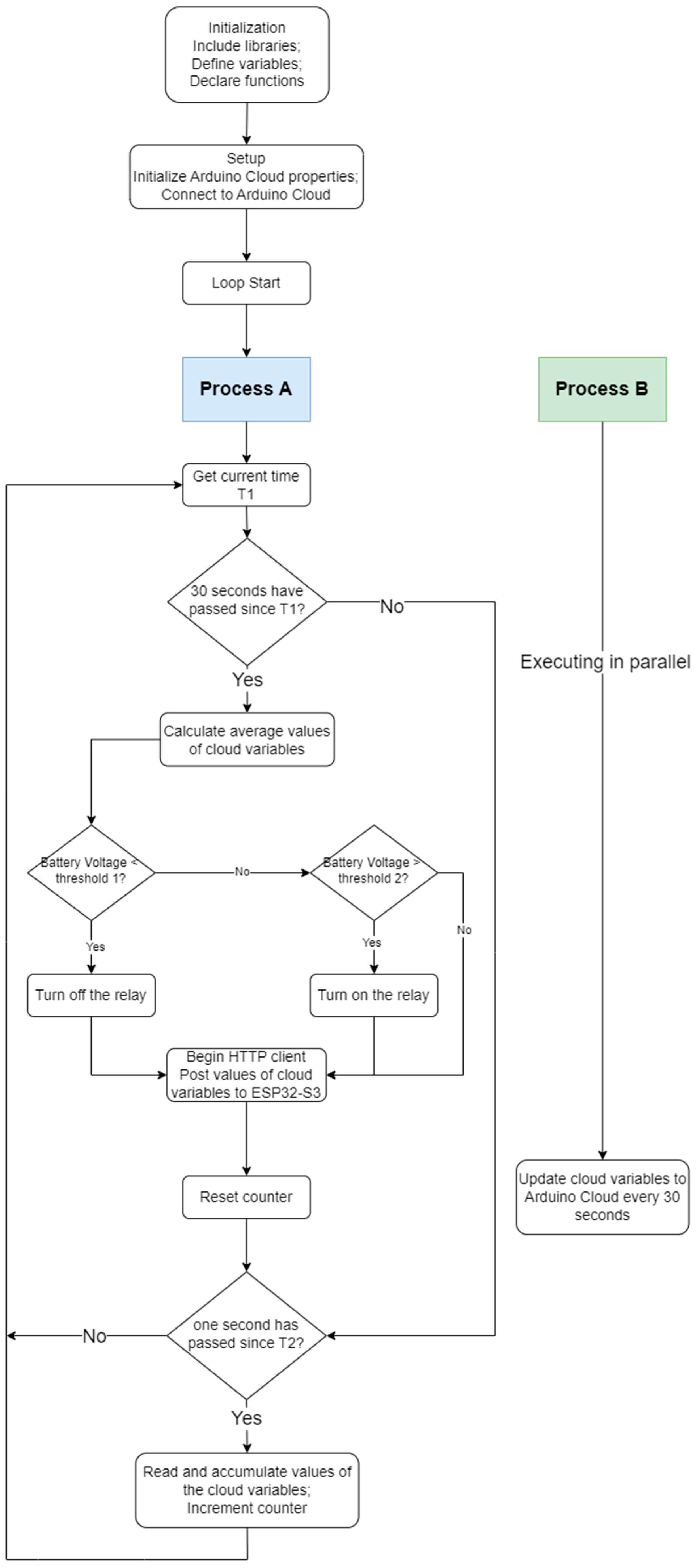
5. Implementation Methodology
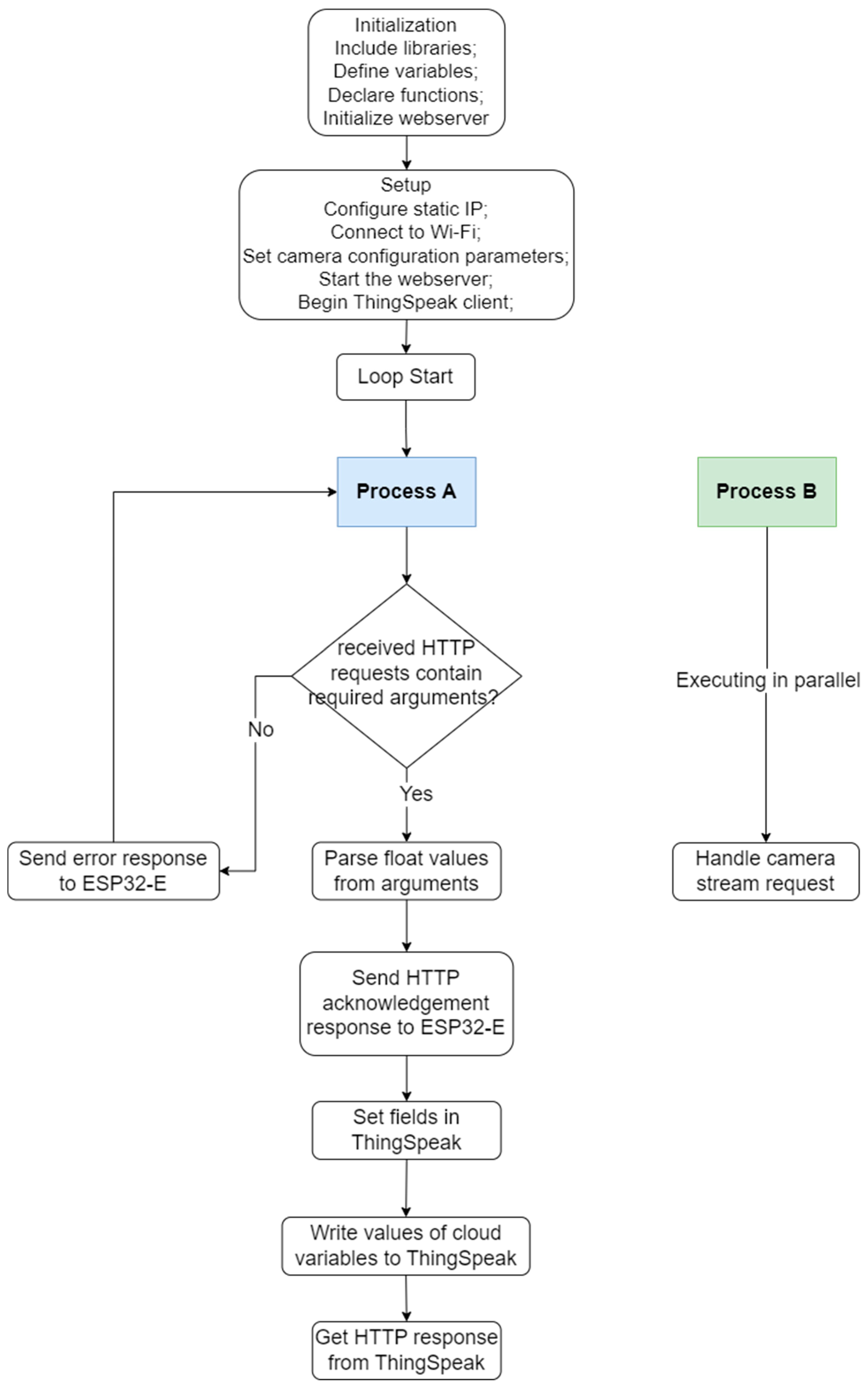
| Algorithm 1: Data acquisition, automatic control, and data communication by ESP32-E. |
Initialization;
|
| Algorithm 2: Data communication, and camera web server by ESP32-S3. |
Initialization;
If received requests contain required arguments (such as “pv_voltage”) then
|
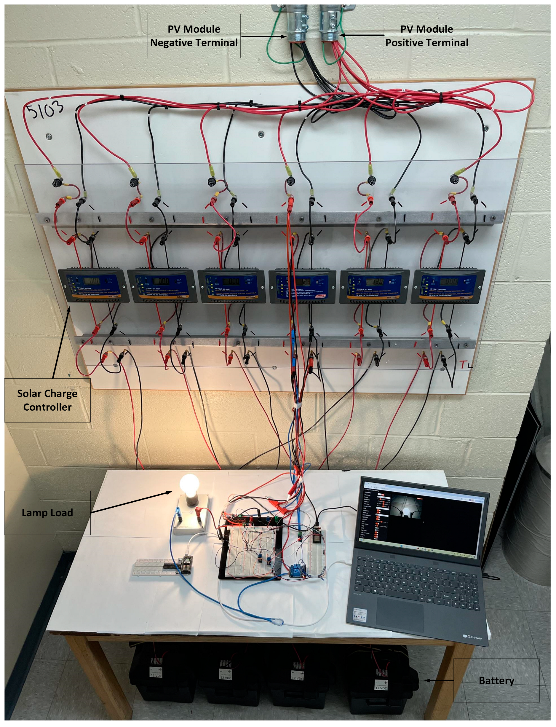
6. Experimental Setup
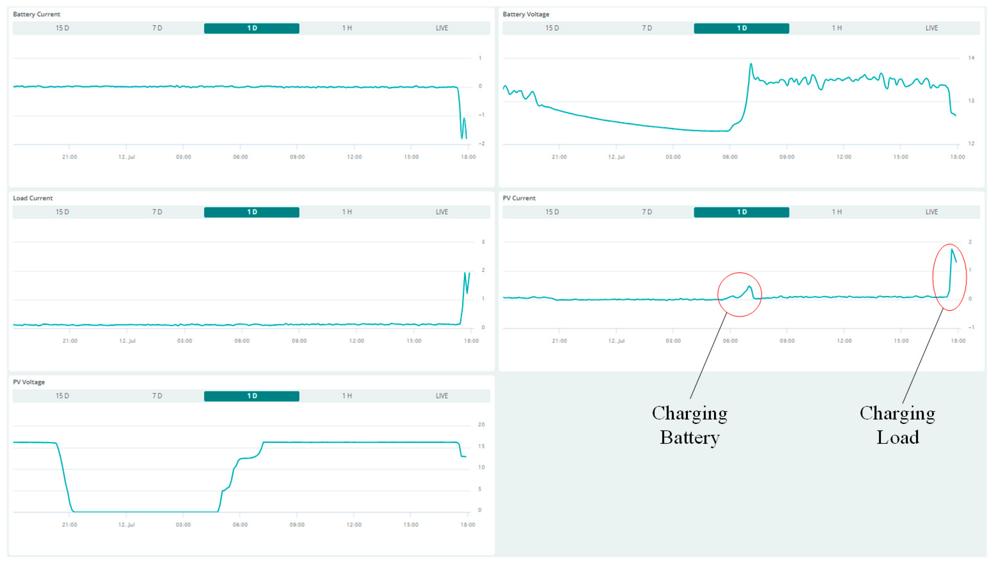
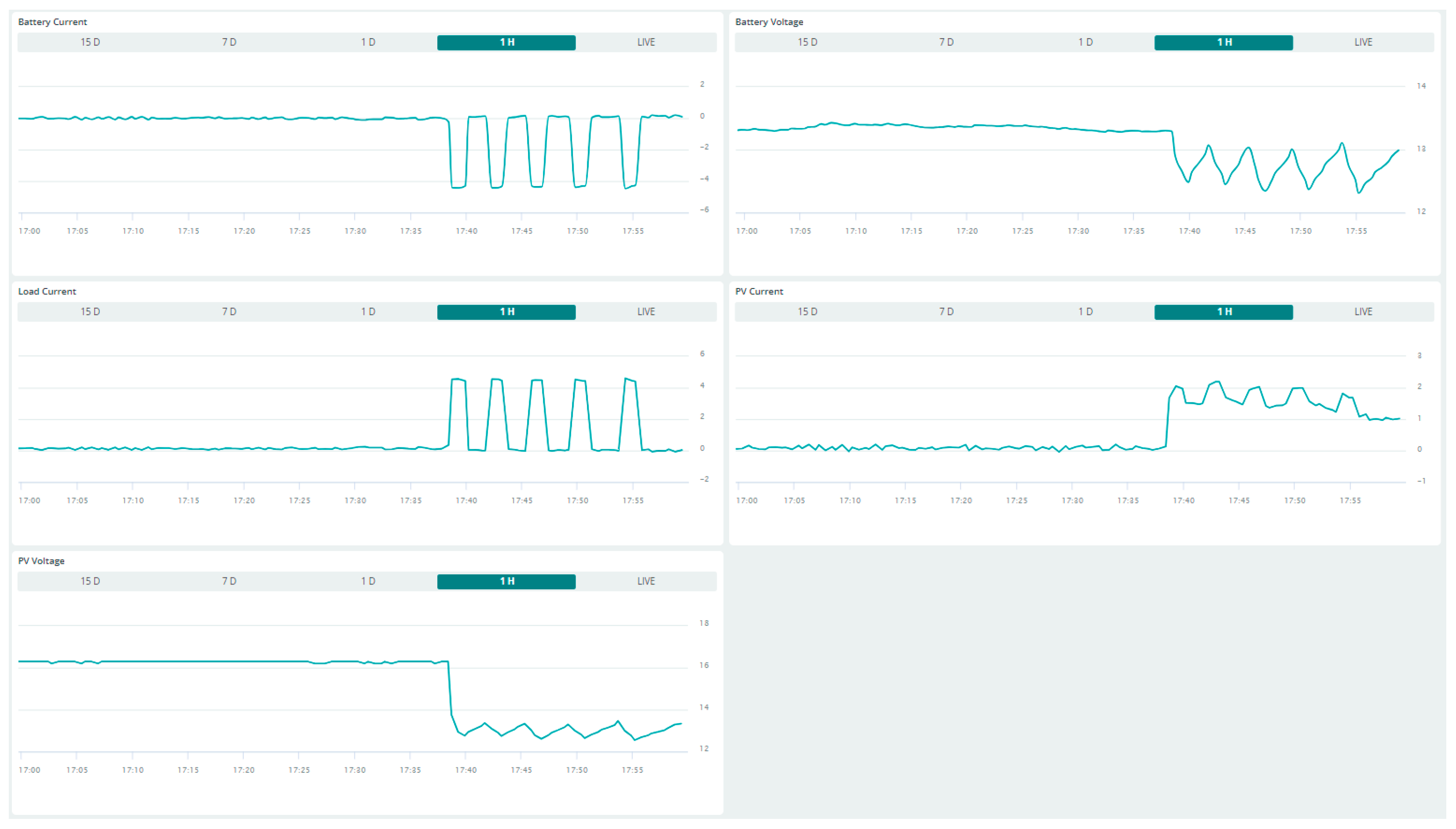
7. Results
8. Discussion
- Integration of dual IoT Platforms: The Arduino Cloud and ThingSpeak are two of the most popular IoT platforms, which facilitate easy and powerful IoT integration into SCADA systems. The communication layer, security layer, and application layer can all be implemented on the two platforms. The Arduino Cloud offers exclusive benefits over ThingSpeak, including the cloud programming environment, device management, and OTA updates. Comparatively, ThingSpeak provides advanced data analytics, customizable dashboards, integration with MATLAB, and powerful plugins. Both cloud services retain some data that could be accessed later. Using two cloud services at the same time adds highly desirable redundancy and diversity features to the design. This design also has great potential to develop new features in the future with the development and updates of the two IoT platforms.
- Dual Microcontrollers: ESP32-E focuses on collecting the PV system parameters and control, which requires electrical connections with the PV system circuit through sensors and the relay. Meanwhile, ESP32-S3 is not involved in the physical connection with the PV system but handles image collection and data transmission. This separation of duties improves the system’s reliability at the hardware level. Furthermore, the use of dual microcontrollers provides flexibility in monitoring tasks. While it is possible to mount the camera module on the microcontroller that collects the system parameters, this setup would significantly limit the range of inspection objects. This limitation arises from the need to align both the system’s electrical ports and the inspection area simultaneously. For instance, if the inspected lamp load (or a PV panel in other scenarios) is located outdoors and the electrical ports are indoors, a single microcontroller would be insufficient to meet these requirements.
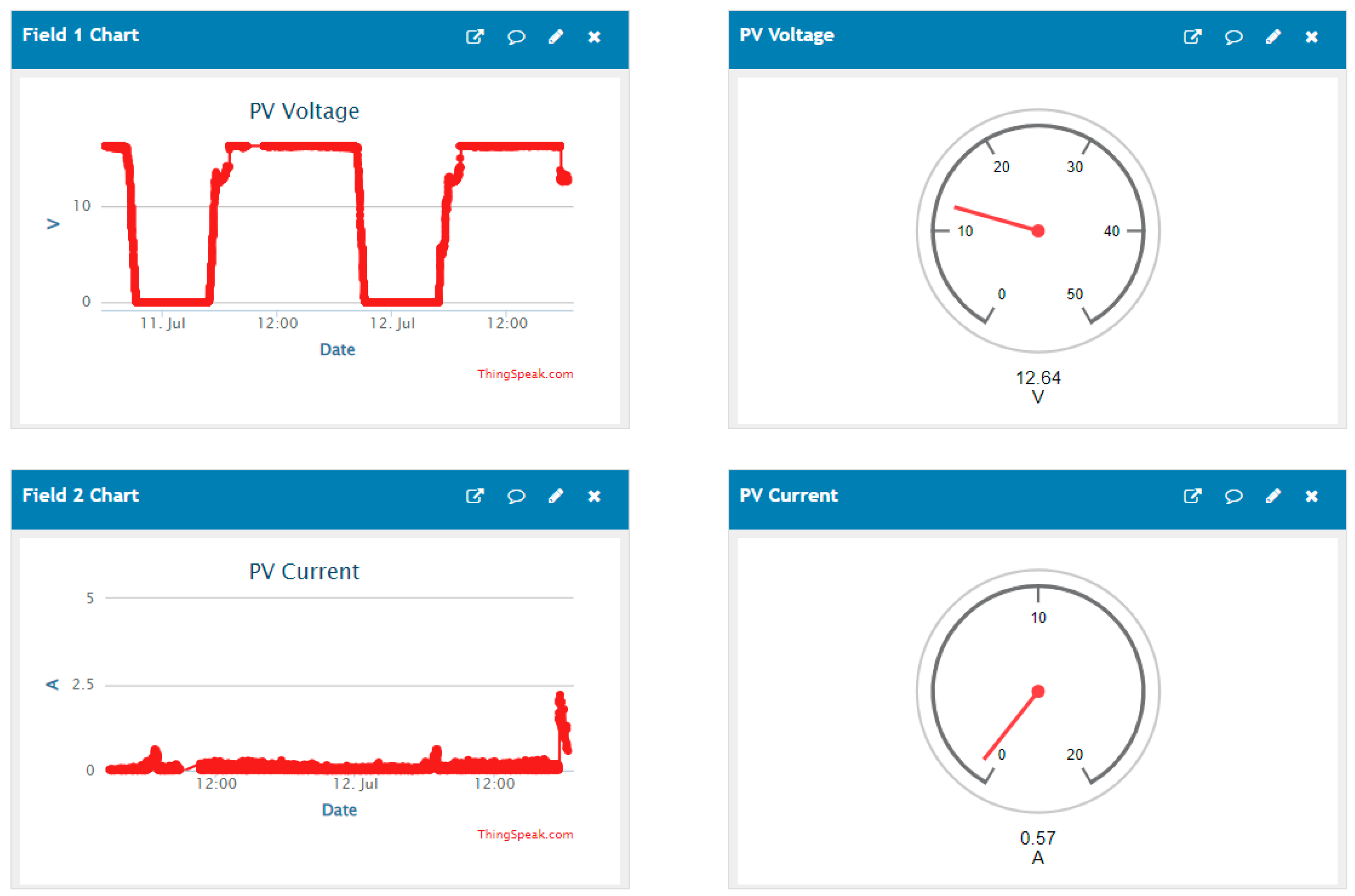
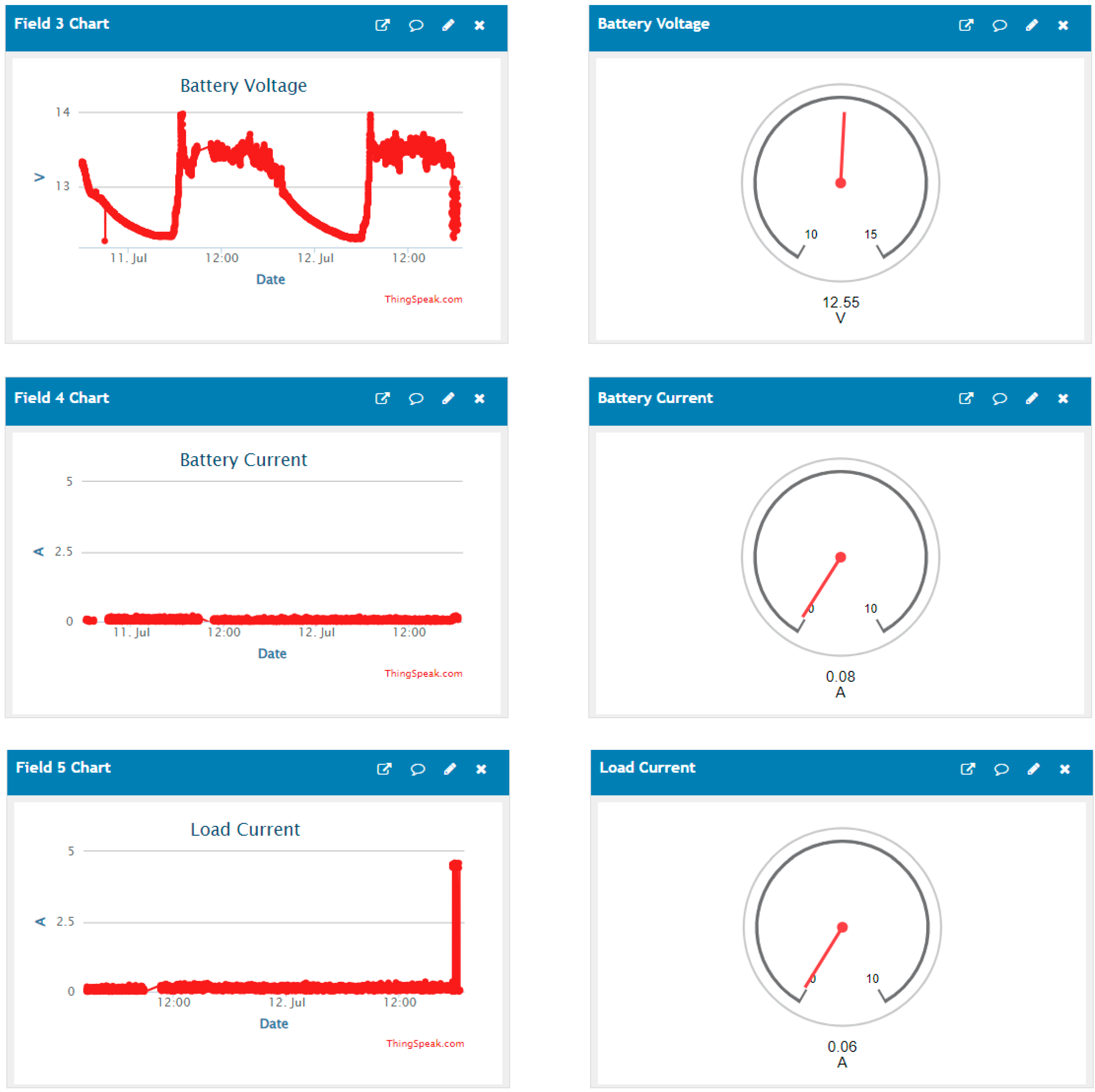
- Real-time Monitoring and HMI design: The Arduino Cloud and ThingSpeak receive voltage and current data every 30 s. Fast responses to incidents can be made to prevent potential losses. Furthermore, the two platforms provide customizable and easy-to-use dashboards for HMI.
- Data Redundancy: When the Arduino Cloud was offline, the IoT-SCADA system continued to log data on ThingSpeak, which ensures the overall system reliability and accessibility.
- Image-based Load Monitoring: A low-cost camera web server allows users to capture images of the load. Visual surveillance ensures that no lamp is burned out and the surrounding environment remains safe, and it provides more intuitive feedback than electrical parameters alone. By observing the load image, operators obtain awareness of the load status without being onsite, saving on unnecessary technical service calls. Live feedback is a great tool to remotely oversee the monitored system.
- Automatic Control and alert: A control method is employed in ESP32-E that controls the relay and the load locally. This operation protects the battery from over-discharging automatically. This novel design also has an auto low battery alert though email, which is a great tool to avoid battery dead discharge and extend the battery life.
- System Security: Devices must provide their corresponding keys assigned by the Arduino Cloud to connect to it. Moreover, ThingSpeak requires the channel read/write API key to allow the read/write operation. This method guarantees that only authenticated devices have access to the platforms.
- Cloud Data Storage: In our design, 5 messages are sent to ThingSpeak every 30 s. Since ThingSpeak supports 3 million messages per year free of charge, it can store up to 208 days of data.
- Open-source: IoT platforms, microcontrollers, and actuators are all open source. Free software guides and hardware at a low price are available on the Internet and the market. This removes the barrier of replicating this design, facilitating its promotion.
- Low power consumption: The average power consumptions of the ESP32-S3 with the camera and ESP32-E during working conditions are 0.92 W and 0.81 W, respectively. The total power consumption of the system is merely 2.38 W.
9. Conclusions
10. Future Work
Author Contributions
Funding
Data Availability Statement
Conflicts of Interest
Abbreviations
| SCADA | Supervisory Control and Data Acquisition |
| RTUs | Remote Terminal Units |
| MTUs | Master Terminal Units |
| FIDs | Field Instrumentation Devices |
| HMI | Human–Machine Interface |
| IoT | Internet of Things |
| GPIO | General-purpose Input/Output |
| IDE | Integrated Development Environment |
| PV | Photovoltaic |
| MPPT | Maximum Power Point Tracker |
| RAM | Random Access Memory |
| UART | Universal Asynchronous Receiver Transmitter Pins |
| MQTT | Message Queuing Telemetry Transport |
| HTTP | Hypertext Transfer Protocol |
Appendix A

References
- Aheleroff, S.; Xu, X.; Lu, Y.; Aristizabal, M.; Pablo Velásquez, J.; Joa, B.; Valencia, Y. IoT-enabled smart appliances under industry 4.0: A case study. Adv. Eng. Inform. 2020, 43, 101043. [Google Scholar] [CrossRef]
- Stavropoulos, T.G.; Papastergiou, A.; Mpaltadoros, L.; Nikolopoulos, S.; Kompatsiaris, I. IoT Wearable Sensors and Devices in Elderly Care: A Literature Review. Sensors 2020, 20, 2826. [Google Scholar] [CrossRef]
- Franco, J.; Aris, A.; Canberk, B.; Uluagac, A.S. A Survey of Honeypots and Honeynets for Internet of Things, Industrial Internet of Things, and Cyber-Physical Systems. IEEE Commun. Surv. Tutor. 2021, 23, 2351–2383. [Google Scholar] [CrossRef]
- Wang, Q.; Zhu, X.; Ni, Y.; Gu, L.; Zhu, H. Blockchain for the IoT and industrial IoT: A review. Internet Things 2020, 10, 100081. [Google Scholar] [CrossRef]
- Rejeb, A.; Rejeb, K.; Simske, S.; Treiblmaier, H.; Zailani, S. The big picture on the internet of things and the smart city: A review of what we know and what we need to know. Internet Things 2022, 19, 100565. [Google Scholar] [CrossRef]
- Mohamed, R.; Behiri, M.A.M.; Mohammed, J. Al shammri, Hegazy Rezk. Energy Performance Analysis of On-Grid Solar Photovoltaic System-a Practical Case Study. Int. J. Renew. Energy Res. IJRER 2019, 9, 1292–1301. [Google Scholar] [CrossRef]
- Yadav, G.; Paul, K. Architecture and security of SCADA systems: A review. Int. J. Crit. Infrastruct. Prot. 2021, 34, 100433. [Google Scholar] [CrossRef]
- Alanazi, M.; Mahmood, A.; Chowdhury, M.J.M. SCADA vulnerabilities and attacks: A review of the state-of-the-art and open issues. Comput. Secur. 2023, 125, 103028. [Google Scholar] [CrossRef]
- Sajid, A.; Abbas, H.; Saleem, K. Cloud-Assisted IoT-Based SCADA Systems Security: A Review of the State of the Art and Future Challenges. IEEE Access 2016, 4, 1375–1384. [Google Scholar] [CrossRef]
- Babayigit, B.; Abubaker, M. Industrial Internet of Things: A Review of Improvements Over Traditional SCADA Systems for Industrial Automation. IEEE Syst. J. 2024, 18, 120–133. [Google Scholar] [CrossRef]
- Pliatsios, D.; Sarigiannidis, P.; Lagkas, T.; Sarigiannidis, A.G. A Survey on SCADA Systems: Secure Protocols, Incidents, Threats and Tactics. IEEE Commun. Surv. Tutor. 2020, 22, 1942–1976. [Google Scholar] [CrossRef]
- Duair, J.J.; Majeed, A.I.; Ali, G.M. Design and Implementation of IoT-Based SCADA for a Multi Microgrid System. ECS Trans. 2022, 107, 17345. [Google Scholar] [CrossRef]
- Alhasnawi, B.N.; Jasim, B.H.; Alhasnawi, A.N.; Sedhom, B.E.; Jasim, A.M.; Khalili, A.; Bureš, V.; Burgio, A.; Siano, P. A Novel Approach to Achieve MPPT for Photovoltaic System Based SCADA. Energies 2022, 15, 8480. [Google Scholar] [CrossRef]
- de Arquer Fernández, P.; Fernández Fernández, M.Á.; Carús Candás, J.L.; Arboleya Arboleya, P. An IoT open source platform for photovoltaic plants supervision. Int. J. Electr. Power Energy Syst. 2021, 125, 106540. [Google Scholar] [CrossRef]
- Silva, F.M.Q.; Filho, B.J.C.; Pires, I.A.; Maia, T.A.C. Design of a SCADA System Based on Open-Source Tools. In Proceedings of the 2021 14th IEEE International Conference on Industry Applications (INDUSCON), Sao Paulo, Brazil, 15–18 August 2021; pp. 1323–1328. [Google Scholar]
- Melo, G.C.; Torres, I.C.; Araújo, Í.B.; Brito, D.B.; Barboza, E.D. A Low-Cost IoT System for Real-Time Monitoring of Climatic Variables and Photovoltaic Generation for Smart Grid Application. Sensors 2021, 21, 3293. [Google Scholar] [CrossRef]
- Hoarcă, I.C. Energy management for a photovoltaic power plant based on SCADA system. In Proceedings of the 2021 13th International Conference on Electronics, Computers and Artificial Intelligence (ECAI), Pitesti, Romania, 1–3 July 2021; pp. 1–9. [Google Scholar]
- Vujović, I.; Mladen, K.; Željko, Đ. Centralized controlling of distributed PV systems using cloud and IoT technologies. Telfor J. 2023, 15, 6. [Google Scholar] [CrossRef]
- Sarkar, S.; Rao, K.U.; Bhargav, J.; Sheshaprasad, S.; C.A, A.S. IoT Based Wireless Sensor Network (WSN) for Condition Monitoring of Low Power Rooftop PV Panels. In Proceedings of the 2019 IEEE 4th International Conference on Condition Assessment Techniques in Electrical Systems (CATCON), Piscataway, NJ, USA, 21–23 November 2019; pp. 1–5. [Google Scholar]
- Dupont, I.M.; Carvalho, P.C.M.; Jucá, S.C.S.; Neto, J.S.P. Novel methodology for detecting non-ideal operating conditions for grid-connected photovoltaic plants using Internet of Things architecture. Energy Convers. Manag. 2019, 200, 112078. [Google Scholar] [CrossRef]
- Seflahir, D.; Ahmad Faisal Mohamad, A.; Aliashim, A.; Abdurahman; Nurul, H.; Rivaldi, K.; Ojak Abdul, R. Real-time Analysis of Inverter Performance via SCADA Haiwell Online Monitoring. J. Adv. Res. Appl. Sci. Eng. Technol. 2024, 37, 99–114. [Google Scholar] [CrossRef]
- Mellit, A.; Benghanem, M.; Kalogirou, S.; Massi Pavan, A. An embedded system for remote monitoring and fault diagnosis of photovoltaic arrays using machine learning and the internet of things. Renew. Energy 2023, 208, 399–408. [Google Scholar] [CrossRef]
- Khelil, A.; Germanus, D.; Suri, N. Protection of SCADA Communication Channels. In Critical Infrastructure Protection: Information Infrastructure Models, Analysis, and Defense; Lopez, J., Setola, R., Wolthusen, S.D., Eds.; Springer: Berlin/Heidelberg, Germany, 2012; pp. 177–196. [Google Scholar]
- Aghenta, L.O.; Iqbal, M.T. Low-Cost, Open Source IoT-Based SCADA System Design Using Thinger.IO and ESP32 Thing. Electronics 2019, 8, 822. [Google Scholar] [CrossRef]
- He, W.; Baig, M.J.; Iqbal, M.T. An Open-Source Supervisory Control and Data Acquisition Architecture for Photovoltaic System Monitoring Using ESP32, Banana Pi M4, and Node-RED. Energies 2024, 17, 2295. [Google Scholar] [CrossRef]
- Naderi, E.; Asrari, A. A Deep Learning Framework to Identify Remedial Action Schemes Against False Data Injection Cyberattacks Targeting Smart Power Systems. IEEE Trans. Ind. Inform. 2024, 20, 1208–1219. [Google Scholar] [CrossRef]
- Naderi, E.; Aydeger, A.; Asrari, A. Detection of False Data Injection Cyberattacks Targeting Smart Transmission/Distribution Networks. In Proceedings of the 2022 IEEE Conference on Technologies for Sustainability (SusTech), Virtual, 21–23 April 2022; pp. 224–229. [Google Scholar]
- Naderi, E.; Asrari, A. Toward Detecting Cyberattacks Targeting Modern Power Grids: A Deep Learning Framework. In Proceedings of the 2022 IEEE World AI IoT Congress (AIIoT), Seattle, WA, USA, 6–9 June 2022; pp. 357–363. [Google Scholar]
- Cui, Y.; Liu, M.; Li, W.; Lian, J.; Yao, Y.; Gao, X.; Yu, L.; Wang, T.; Li, Y.; Yin, J. An exploratory framework to identify dust on photovoltaic panels in offshore floating solar power stations. Energy 2024, 307, 132559. [Google Scholar] [CrossRef]
- Yang, M.; Javed, W.; Guo, B.; Ji, J. Estimating PV Soiling Loss Using Panel Images and a Feature-Based Regression Model. IEEE J. Photovolt. 2024, 14, 661–668. [Google Scholar] [CrossRef]
- David, M.; Alonso-Montesinos, J.; Le Gal La Salle, J.; Lauret, P. Probabilistic Solar Forecasts as a Binary Event Using a Sky Camera. Energies 2023, 16, 7125. [Google Scholar] [CrossRef]
- Espressif Systems. ESP32-S3-WROOM-1 ESP32-S3-WROOM-1U Datasheet. Available online: https://www.espressif.com/sites/default/files/documentation/esp32-s3-wroom-1_wroom-1u_datasheet_en.pdf (accessed on 3 July 2024).
- Espressif Systems. ESP32-WROOM-32E ESP32-WROOM-32UE Datasheet. Available online: https://www.espressif.com/sites/default/files/documentation/esp32-wroom-32e_esp32-wroom-32ue_datasheet_en.pdf (accessed on 4 July 2024).
- Geekstory Voltage Tester Sensor Measurement Detection Module DC 0-25V Terminal Sensor Module for Arduino UNO Mega Robot Smart Car Geekstory (Pack of 10). Available online: https://www.amazon.ca/Voltage-Measurement-Detection-Arduino-Geekstory/dp/B07FVVSYYH (accessed on 5 June 2024).
- SparkFun Electronics. ACS712 Datasheet. Available online: https://www.sparkfun.com/datasheets/BreakoutBoards/0712.pdf (accessed on 5 July 2024).
- OmniVision. OV2640 Color CMOS UXGA (2.0 MegaPixel) CameraChip with OminiPixel2 Technology. Available online: https://www.uctronics.com/download/cam_module/OV2640DS.pdf (accessed on 5 July 2024).
- ArduCam. Arducam OV2640 Camera Module, 2MP Mini CCM Compact Camera Modules Compatible with Arduino ESP32 ESP8266 Development Board with DVP 24 Pin Interface. Available online: https://www.arducam.com/product/arducam-ov2640-camera-module-2mp-mini-ccm-compact-camera-modules-compatible-with-arduino_m0031esp32-esp8266-development-board-with-dvp-24-pin-interface_/ (accessed on 5 July 2024).
- Arduino Cloud. Scheduled Maintenance for Arduino Cloud. Available online: https://status.arduino.cc/incidents/3zbncwd7k7vl (accessed on 12 July 2024).
- He, W.; Iqbal, M.T. Power Consumption Minimization of a Low-Cost IoT Data Logger for Photovoltaic System. J. Electron. Electr. Eng. 2023, 2, 241–261. [Google Scholar] [CrossRef]


| Reference | Monitored Parameter Types | IoT Platforms |
|---|---|---|
| [12] | Voltage, current, temperature | Cayenne |
| [13] | Voltage, power, MQTT duty cycle | ThingSpeak |
| [14] | Voltage, current, power, solar irradiation | Eclipse Kapua |
| [15] | Voltage, current, power, energy, environmental measurements | Emoncms |
| [16] | Voltage, current, power, meteorological variables | Google Cloud Platform |
| [19] | Voltage, current, power, temperature and humidity, dust | Ubidots Cloud |
| [20] | Voltage, current, power, solar irradiance, Ambient and PV module temperature | Apache (web server) |
| [21] | Voltage, current, active/reactive power, grid frequency | Haiwell Cloud |
| [22] | Voltage, current, power, ambient and PV module temperature | Blynk IoT |
| [24] | Voltage, current, power | Thinger.IO |
| [25] | Voltage, current, power | Node-RED |
| This design | Voltage, current, power, graphic image | Arduino Cloud and ThingSpeak |
Disclaimer/Publisher’s Note: The statements, opinions and data contained in all publications are solely those of the individual author(s) and contributor(s) and not of MDPI and/or the editor(s). MDPI and/or the editor(s) disclaim responsibility for any injury to people or property resulting from any ideas, methods, instructions or products referred to in the content. |
© 2024 by the authors. Licensee MDPI, Basel, Switzerland. This article is an open access article distributed under the terms and conditions of the Creative Commons Attribution (CC BY) license (https://creativecommons.org/licenses/by/4.0/).
Share and Cite
He, W.; Baig, M.J.A.; Iqbal, M.T. An Internet of Things—Supervisory Control and Data Acquisition (IoT-SCADA) Architecture for Photovoltaic System Monitoring, Control, and Inspection in Real Time. Electronics 2025, 14, 42. https://doi.org/10.3390/electronics14010042
He W, Baig MJA, Iqbal MT. An Internet of Things—Supervisory Control and Data Acquisition (IoT-SCADA) Architecture for Photovoltaic System Monitoring, Control, and Inspection in Real Time. Electronics. 2025; 14(1):42. https://doi.org/10.3390/electronics14010042
Chicago/Turabian StyleHe, Wei, Mirza Jabbar Aziz Baig, and Mohammad Tariq Iqbal. 2025. "An Internet of Things—Supervisory Control and Data Acquisition (IoT-SCADA) Architecture for Photovoltaic System Monitoring, Control, and Inspection in Real Time" Electronics 14, no. 1: 42. https://doi.org/10.3390/electronics14010042
APA StyleHe, W., Baig, M. J. A., & Iqbal, M. T. (2025). An Internet of Things—Supervisory Control and Data Acquisition (IoT-SCADA) Architecture for Photovoltaic System Monitoring, Control, and Inspection in Real Time. Electronics, 14(1), 42. https://doi.org/10.3390/electronics14010042