Abstract
The study of multilevel dual-active-bridge (DAB) converters has garnered significant attention in recent years thanks to their advantages with respect to the conventional two-level (2L) DAB; namely, its greater performance and its capability to operate at higher voltage. The analysis of the converter high-frequency inductor current () is crucial, for instance, to compute its root mean square (RMS) value, required to estimate the conduction losses in the converter. The mathematical expression of is piecewise and multiple variations, i.e., modes, exist depending on the modulation parameter values. This increases the complexity of converter performance analytical study. Thus, a more practical and generalizable expression of current is desirable. This paper proposes novel compact analytic expressions for the instantaneous and RMS inductor current in the 2L-NL DAB converter, leveraging binary functions to define the piecewise intervals and to identify the mode as a function of the modulation parameter values. The proposed method paves the way for more simple and computationally efficient DAB performance optimization software tools that allow exploring any given converter structures and modulation strategies.
1. Introduction
Dual-active-bridge (DAB) dc-dc converters have become popular in industrial applications due to their great efficiency and power density. As the demand for high-performance power conversion continues to rise, DAB converter topologies have emerged as an attractive solution, particularly in systems that require both bidirectional power flow and galvanic isolation [1,2]. Moreover, the introduction of multilevel (ML) converter-leg topologies in the DAB offer several performance gains [3,4]. For instance, for the same semiconductor device voltage rating, ML topologies allow increasing the dc-port voltages and the converter power rating, compared to conventional two-level (2L) topologies. On the other hand, for the same dc-port voltage, they allow reducing the converter conduction and switching losses by using lower-voltage-rated semiconductor devices with better performance figures and cost benefit ratios. Additionally, ML topologies open the door to advanced modulation techniques that leverage the additional degree of freedom offered by the ML ac-voltage waveforms to further improve the converter performance [5,6,7]. ML DAB converters have a wide range of applications, such as solid-state transformers [8,9], high-power battery storage systems [10,11], electric vehicles fast-charging stations [12,13] or low-voltage dc distribution systems [14,15,16,17]. They may also be applicable to lower power applications, given their comparable better performance as a trade-off of cost and complexity.
The performance analysis of ML DAB converters requires an accurate study of the current flowing through its high-frequency inductor (). For instance, it allows determining the root mean square (RMS) current flowing through the power semiconductor devices and passive components and thus computing their conduction losses. Therefore, an accurate expression for in the form of a piecewise expression is necessary for the analysis of the converter [7,14,18,19].
However, the piecewise-defined nature of presents a challenge for its study. When any of the DAB ac-voltage waveforms presents more than two voltage levels, different piecewise expressions for arise (known as “modes” or “cases” in the literature), each one valid for different intervals of the modulation parameters, i.e., the phase shift and voltage waveform duty cycles. The number of expressions increases as the number of levels in the ac-voltage waveform increases, for instance, when ML converter leg topologies are employed in the DAB. Thus, ML DAB performance analysis through the analytical study of the piecewise expressions becomes complex and laborious.
To address this challenge, this paper proposes a generalized and compact mathematical function that provides the DAB piecewise expression, employing binary indicator functions to define the piecewise intervals and to identify the mode as a function of the modulation parameter values. The proposed expression is valid for any DAB featuring a two-level square-wave ac voltage on one side and a staircase-wave ac voltage with any number of levels on the other side, i.e., a 2L-NL ML DAB converter. With the proposed generalized function, the paper also provides the generalized function for the DAB inductor RMS current.
The rest of the paper is organized as follows: First, Section 2 derives the proposed generalized function that provides the compact expressions for instantaneous and RMS values for a 2L-NL DAB converter. The generalization to N levels is accomplished by following an inductive process, first analyzing the 2L-3L DAB and 2L-4L DAB cases and finally inferring the generalized function. Then, Section 3 validates the proposed function by comparing numerically and graphically for multiple modulation parameter values against the results obtained through Fourier analysis of the current. Section 4 performs a comparison of the computational time required to obtain instantaneous and RMS values using the compact expressions and through Fourier analysis. Finally, Section 5 discusses the implications of the proposed method and outlines future research work.
2. Derivation of the Generalized Inductor Current Expression
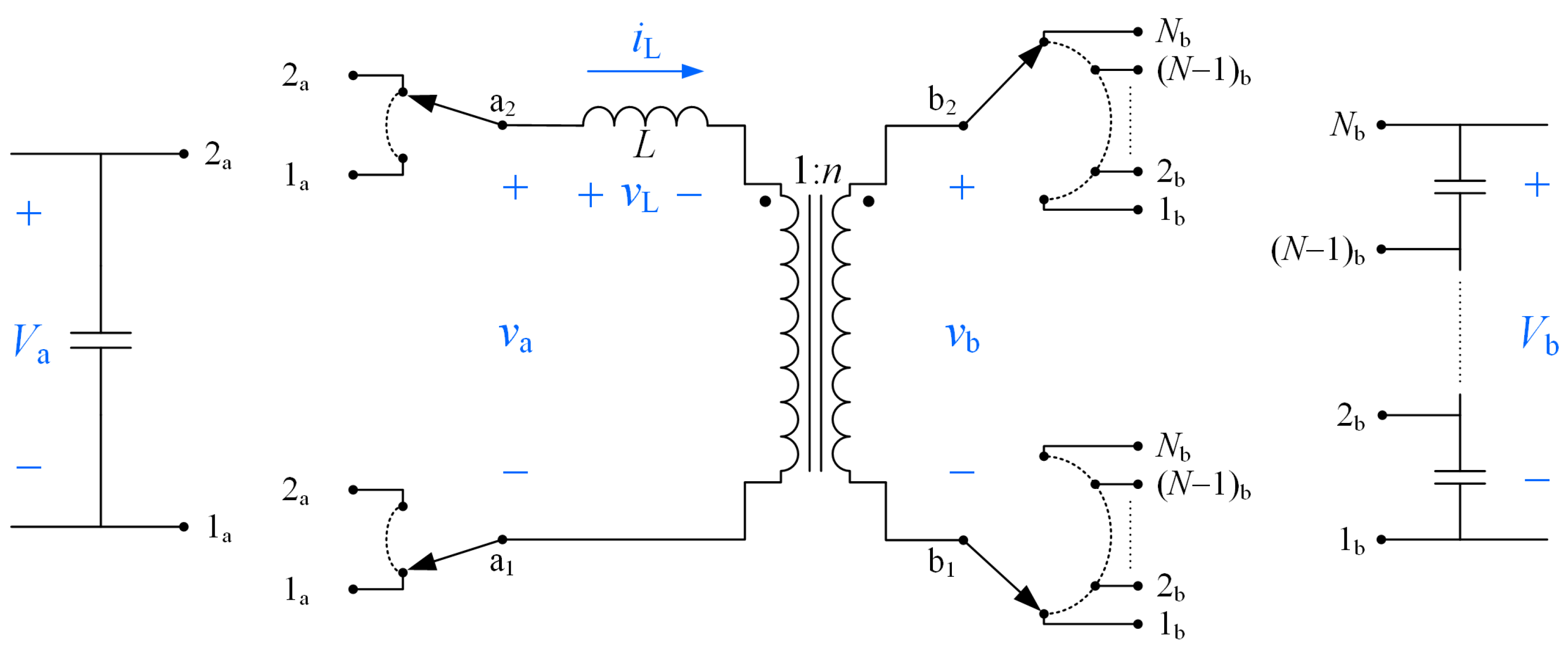
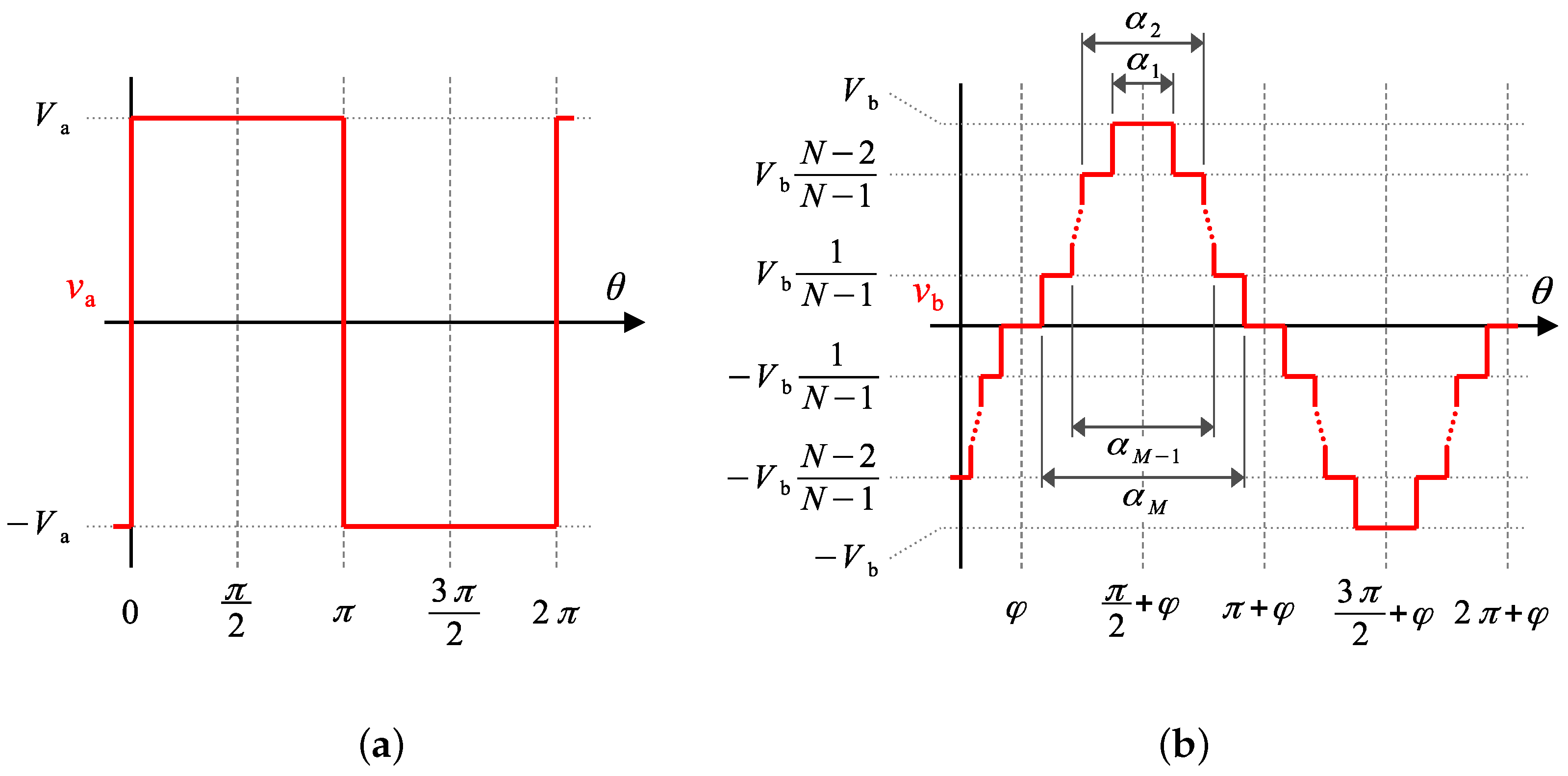
Let us consider the ideal lossless ML DAB converter shown in Figure 1, featuring two 2L converter legs in side a and two NL NPC converter legs in side b, that is, a single-phase 2L-NL DAB converter. Such a converter is capable of synthesizing an ac-voltage waveform with two voltage levels in side a () and voltage levels in side b (), as shown in Figure 2a and Figure 2b, respectively. Parameters and are the dc-link voltages of sides a and b of the converter, respectively. Let us consider that the capacitance in the converter dc port is large enough such that and are constant over each waveform step interval. Let us also consider a modulation where and present quarter-wave symmetry and that it works in steady-state operation. As shown in Figure 2, a total of N modulation angles are used, which are defined as the phase shift between and , , and the angles controlling the dwell times of the voltage pulses in , {, , ..., }, where and
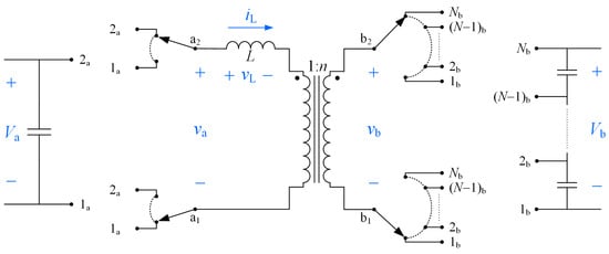
Figure 1.
Topology of the considered ML DAB converter. Neutral-point-clamped (NPC) converter legs are considered, represented as single-pole double-throw switches in side a and as single-pole multiple-throw switches in side b. Relevant electrical variables are shown in blue.
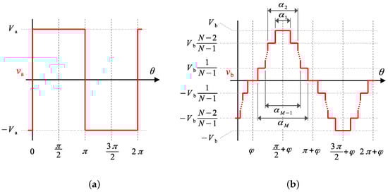
Figure 2.
Synthesized ac-voltage waveforms and modulation parameters in the considered 2L-NL DAB. (a) a-side voltage (). (b) b-side voltage () and its modulation parameters.
It should be noted that other ML converter-leg topologies could be considered, such as flying-capacitor [20] or modular-ML [21] topologies.
2.1. 2L-3L DAB Instantaneous Current Compact Expression
The voltage across the series inductor in the DAB converter, , is
where n is the inverse of the converter transformer turns ratio. Then, the slope of the current through the inductor, , is
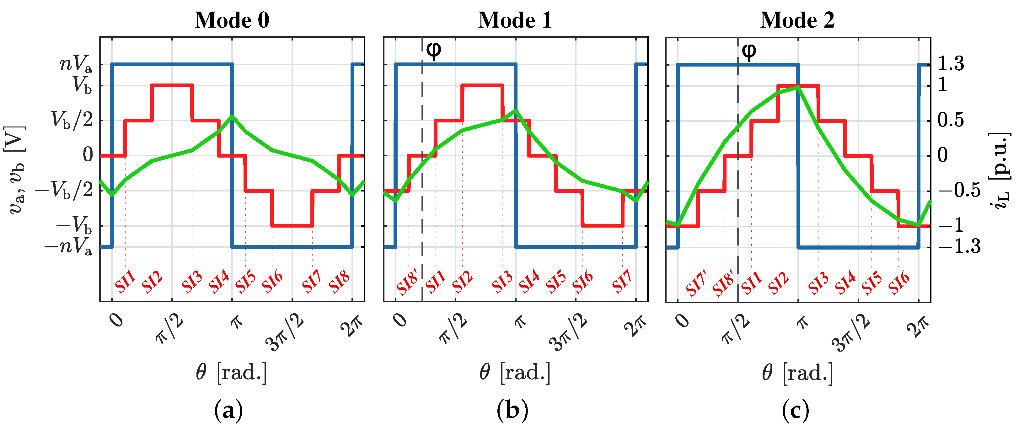
where L is the equivalent inductance given by the series connection of the transformer leakage inductance and an external series inductor. Given the stepped nature of voltages and , the mathematical expression of is piecewise-defined, where each segment of the piecewise current shape is delimited by the instants when and feature a rising or falling edge (switching instants). Figure 3 shows three examples of , , and . This figure reveals that, for a given , , n, and L, the sequence of slope values present in within a switching period () depends on the specific values of the modulation parameters. For instance, in the waveform shown in Figure 3a, the first interval () has a slope , the second interval () has and so on. However, in Figure 3b, the first interval () has a slope , the second interval () has a slope , and so on. From Figure 3, it can be inferred that different piecewise expressions for exist depending on the position of the switching instants with respect to those of ; i.e., different modes exist.
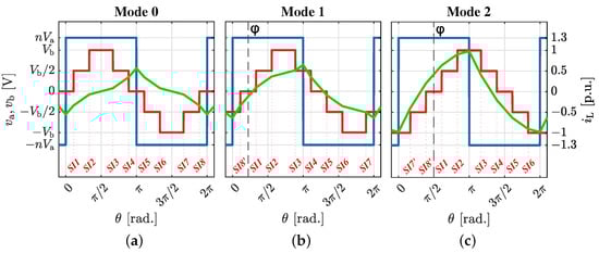
Figure 3.
ac-voltages (blue waveform) and (red) and current (green) for different modes in the 2L-3L DAB converter. All current values are divided by the peak current in Mode 2. Switching angles are (a) Mode 0, with . (b) Mode 1, with . (c) Mode 2, with .
In the 2L-3L DAB three different modes arise, referred to as Mode 0, Mode 1, and Mode 2 (c.f. Figure 3). One can identify each mode with
Based on Equation (5), let us define the binary function associated to as
to allow for an automatic detection of each mode for a given set of modulation parameter values. The values of and for each mode in the 2L-3L converter are
Let us now define and over the whole switching period by means of the indicator function and the binary function defined previously, such that
where when and otherwise, and
correspond to the switching instants of as depicted in Figure 3.
The instantaneous current through the series inductance is
where f is the converter switching frequency. Let us separate the integral terms in Equation (11) into two terms, such as
Let us also define the integral of an indicator function using the min function, such as
The expressions of and can now be substituted into Equation (12) to obtain the compact expression. On the one hand, the term in Equation (12) is solved as
On the other hand, solving involves integrating both and functions. Since the value of does not depend on the variable of integration (), it is treated as a constant parameter, facilitating the resolution of the integral. The result is simplified by grouping the common factors of the expression, and
solution is obtained, where , and are defined as
In the DAB converter, the average value for the inductor current over a switching period is zero, i.e., . Then,
Solving in Equation (19) and substituting it into Equation (18), the compact analytic expression for in a 2L-3L DAB converter is obtained, such as
Note that Equation (20) transitions smoothly between consecutive modes; i.e., the expression for is the same when the boundary condition is met. For example, the boundary between Mode 0 to Mode 1 is defined by . Imposing this condition to Equation (20) on Mode 0 and on Mode 1 results in the same mathematical expression.
2.2. Generalized Current Compact Expression of a 2L-NL DAB
Defining the compact analytical expression for the instantaneous current through the series inductor in a 2L-3L DAB enables us to generalize for a 2L-NL DAB using an inductive process.
First, the compact analytical expression for in a 2L-4L DAB is derived following the methodology employed for the 2L-3L converter, such as
where is defined as
Equations (20) and (21) let us define the structure of the expression for , with the number of levels at side b of the converter, N, and the number of modulation angles controlling the amplitude of the pulses of , M, treated as parameters. Then, the generalized compact expression for in a 2L-NL DAB is defined as
where is
2.3. RMS Expression
The RMS expression for the inductor current in a 2L-NL DAB is defined as
3. Numerical Verification
To verify the proposed DAB inductor current compact expression, the results obtained with the proposed approach are compared with reference results; i.e., results obtained through Fourier analysis up to the harmonic. Then, this section presents the instantaneous and RMS current expressions derived from the Fourier analysis, the numerical verification of the compact analytic expressions for the 2L-3L DAB, and the 2L-4L DAB.
The MATLAB code implementing the functions to compute the inductor-current instantaneous and RMS values with the proposed compact approach are provided as Supplementary Files.
3.1. 2L-NL DAB Instantaneous and RMS Current Expressions Through Fourier Analysis
The expressions for the ac voltage waveforms in a 2L-NL DAB (Figure 2) obtained through Fourier analysis are
where h is the harmonic index and and are the -harmonic voltage phasors,
and and are the amplitudes of the and harmonic, respectively. Then, from Equations (3) and (4), the -harmonic component of the inductor-current phasor is defined as
Then, the expression for the instantaneous current through the series inductor obtained through Fourier analysis is defined as
and its RMS value is obtained from
3.2. Numerical Verification for the 2L-3L DAB
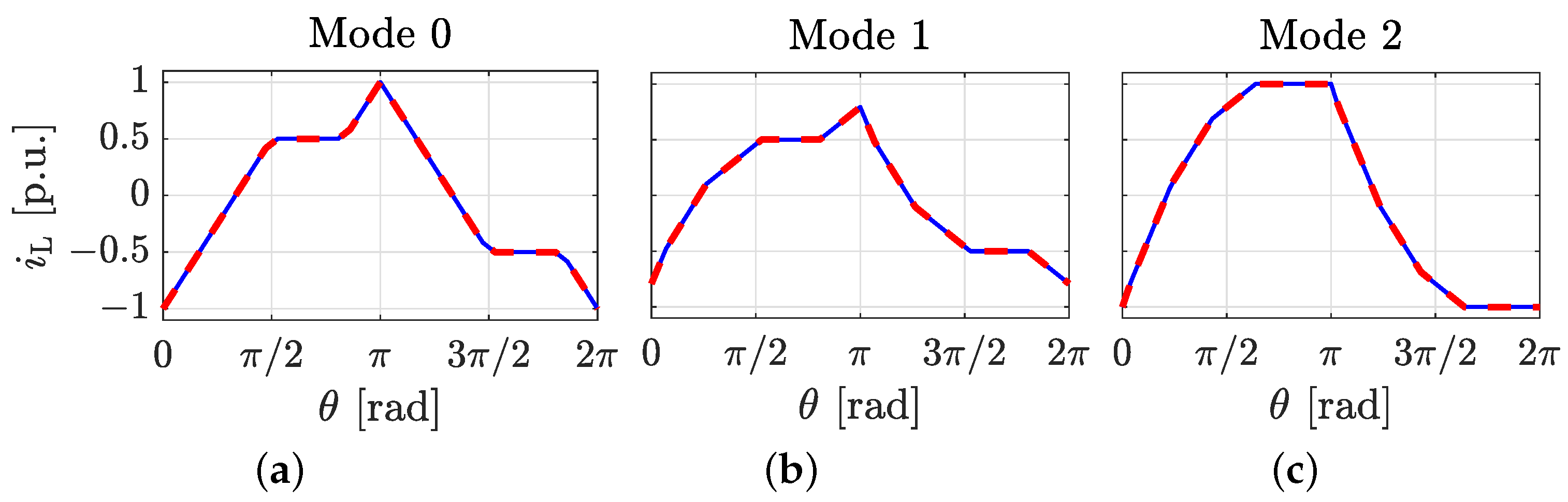
Table 1 and Table 2 provide a comparison of the and per-unit (p.u.) values for the 2L-3L DAB as obtained from the compact analytical expressions (Equation (23) and Equation (26), respectively) and from the Fourier analysis (Equation (32) and Equation (33), respectively). The Table 1 results are obtained for three distinct operation points, defined by the modulation angles , , and , and at five arbitrary values of . The values of the modulation angles have been selected such that each operation point corresponds to a specific mode (Mode 0, Mode 1, and Mode 2, defined in Section 2.1). The Table 2 results are obtained for the same modulation angles as Table 1. The instantaneous and RMS current values obtained using the analytical expression and the Fourier approximation are found to be equal at all three operating points. Furthermore, Figure 4 provides a visual comparison of the waveform obtained using the analytic expression and the Fourier approximation (same operation points as Table 1). As shown, both waveforms are identical throughout the entire switching cycle.

Table 1.
Numerical comparison of using the compact analytical expression () and the Fourier approximation (). All current values are divided by the peak current in Figure 4c.
Table 2.
Numerical comparison of using the compact analytical expression () and the Fourier approximation (). All current values are divided by the peak current in Figure 4c.
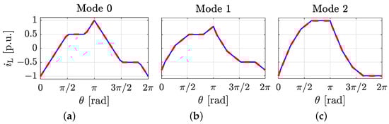
Figure 4.
Waveform of obtained using the compact analytic expression (solid blue line) and the Fourier approximation (dashed red line) at three different operation points. All current values are divided by the peak current in (c). (a) Mode 0, with . (b) Mode 1, with . (c) Mode 2, with .
3.3. Numerical Verification for the 2L-4L DAB
For the purpose of validating the presented compact analytical expressions for the instantaneous and RMS inductor currents, the same verification conducted in Section 3.2 is performed for a 2L-4L DAB. Table 3 and Table 4 provide a comparison of the and p.u. values for the 2L-4L DAB as obtained from the compact analytical expressions and from the Fourier analysis.
Table 3.
Numerical comparison of using the compact analytical expression () and the Fourier approximation (). All current values are divided by the peak current in Figure 5a.
Table 4.
Numerical comparison of using the compact analytical expression () and the Fourier approximation (). All current values are divided by the peak current in Figure 5a.
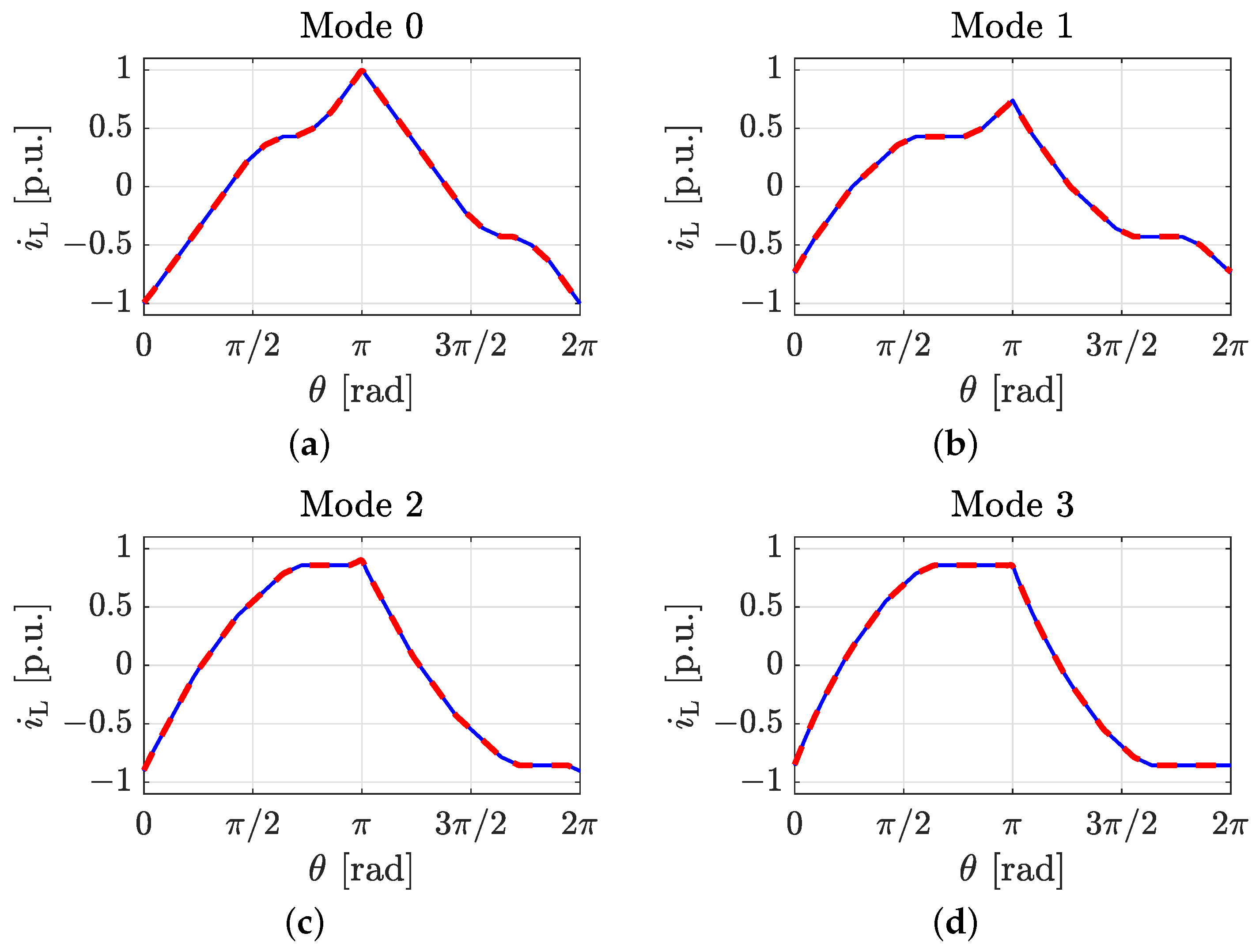
In a 2L-4L DAB converter, four modes arise. The Table 3 and Table 4 results are obtained for four distinct operation points, each operation point corresponding to a specific mode. As can be seen from both tables, the instantaneous and RMS current values obtained using the analytical expression and the Fourier approximation are equal at all four operating points. Furthermore, the visual comparison of the waveform in Figure 5 shows that the analytic expression yields the same results as the Fourier approximation throughout the entire switching cycle for all four operation points (same operation points as Table 3). These results consequently validate the analytical expressions presented in this document.
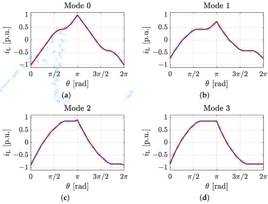
Figure 5.
Waveform of obtained using the compact analytic expression (solid blue line) and the Fourier approximation (dashed red line) at three different operation points. All current values are divided by the peak current in (a). (a) Mode 0, with . (b) Mode 1, with . (c) Mode 2, with . (d) Mode 3, with .
4. Comparative Computational Time Analysis
When developing software tools for the performance optimization of DAB converters, computational time becomes a critical factor, as multiple mathematical expressions must be evaluated a significant number of times to evaluate the converter performance for different operation points and modulation parameter values. In that sense, the expression of the inductor current is crucial, as its RMS value determines the conduction losses of the converter and the instantaneous value determines the power-semiconductor switching losses and the inductor magnetic-field peak value. Therefore, minimizing the computational time required to obtain these magnitudes is essential for developing a faster and more effective optimization tool.
A comparative analysis is conducted on the computational time required to obtain the instantaneous current and its RMS value, using both the compact analytical expressions and the Fourier analysis up to the 63rd harmonic. In performance studies using Fourier analysis, the number of harmonics determines the trade-off between calculation precision and computational time. In the present study, the maximum harmonic index has been selected such that the maximum error in the computation of the instantaneous current is less than 0.01 p.u.
The expressions for the instantaneous current from the proposed compact expressions (Equation (23)) and from the Fourier analysis (Equation (32)) are executed using MATLAB for 100 equally distributed values of in the range . The current at each instant is computed 1000 times, resulting in a total of 100,000 executions. The expressions for the RMS current from the compact expressions (Equation (26)) and from the Fourier analysis (Equation (33)) are executed for 100 randomly generated operation points, defined by the values of the modulation angles. The RMS current for each operation point is computed 1000 times, also resulting in 100,000 executions. The computational time for each execution is measured, and the median computational time required for both currents and methods is obtained.
Table 5 shows the results of this analysis for 3, 4, 5, and 6 levels at side b of the converter. The results show a substantial reduction in computational time when using the compact analytical expression. The analysis reveals that, on average, employing the compact analytical expression allows to reduce by 34.6 times the computational time to obtain the instantaneous value for the inductor current. Furthermore, the computation of the RMS value is, on average, 2.9 times faster when using the compact analytical expression. The results obtained in the comparative computational time analysis then support the advantages of the proposed analytical approach.
Table 5.
Median time to compute the instantaneous and RMS current using the proposed compact expressions and the Fourier approximation for .
5. Discussion
The compact analytical expression for inductor current in ML DAB converters proposed in this paper significantly simplifies performance analysis. By using binary indicator functions, the piecewise nature of the current expression is generalized, allowing for efficient calculation of both instantaneous and RMS values for any arbitrary value of the modulation parameters and any given number of converter voltage levels. This generalization makes the performance analysis versatile and reduces the complexity associated with conventional methods.
The validation results, which agree with results from Fourier analysis, confirm the accuracy of the proposed method across different operating points. Furthermore, as shown in [5,15,18], the DAB inductor current waveforms obtained from an ideal lossless model and from experimental tests are very similar, and thus, the proposed method provides a fair trade-off between simplicity in the expressions and reproducibility of the real current and voltage waveforms. Moreover, the proposed method significantly reduces the computational time required to determine the inductor current in ML converters compared to the Fourier approximation.
These findings align with previous efforts in the field aimed at optimizing multilevel DAB converter topologies to enhance efficiency and reduce power losses, as seen in [5,6,7]. The method paves the way for optimization software tools that allow exploring multiple DAB converter structures and modulation strategies, without requiring ad hoc current expressions for each current mode. Applications like electric vehicles and renewable energy systems might benefit greatly from these tools.
Further work could explore applying this approach to DAB converter configurations with any arbitrary number of levels per side [22] and featuring other modulation techniques [23]. Furthermore, future work includes deriving generalized expressions for the soft-switching-region boundaries in different ML DAB converter topologies and modulation techniques [24,25]. Finally, the same approach can be extended to other converters with piecewise-defined inductor currents, such as the buck, boost, flyback, and resonant dc-dc converters.
Supplementary Materials
The following supporting information can be downloaded at: https://www.mdpi.com/article/10.3390/electronics13224476/s1, MATLAB m-file S1: MATLAB script intended for user execution to obtain the instantaneous inductor current and its RMS value in a ML DAB converter using the proposed mathematical method; MATLAB m-file S2: MATLAB function called by the S1 script to compute and return the instantaneous inductor current; MATLAB m-file S3: MATLAB function called by the S1 script to compute and return the inductor current RMS value.
Author Contributions
Conceptualization, methodology, investigation, validation: E.B.-P., O.E.-M. and A.F.-M.; software: E.B.-P.; formal analysis: E.B.-P.; resources: A.F.-M. and L.T.; writing—original draft preparation and review and editing: E.B.-P., O.E.-M., A.F.-M. and L.T.; supervision: O.E.-M. and A.F.-M.; project administration and funding acquisition: A.F.-M. and L.T. All authors have read and agreed to the published version of the manuscript.
Funding
This work was funded by the European Union’s Horizon Europe research and innovation program under grant agreement No. 101056781. Views and opinions expressed are, however, those of the author(s) only and do not necessarily reflect those of the European Union or CINEA. Neither the European Union nor the granting authority can be held responsible for them.
Data Availability Statement
The original contributions presented in this study are included in the article and supplementary material. Further inquiries can be directed to the corresponding author(s).
Conflicts of Interest
The authors declare no conflict of interest.
References
- Hou, N.; Li, Y.W. Overview and Comparison of Modulation and Control Strategies for a Nonresonant Single-Phase Dual-Active-Bridge DC–DC Converter. IEEE Trans. Power Electron. 2020, 35, 3148–3172. [Google Scholar] [CrossRef]
- Bughneda, A.; Salem, M.; Richelli, A.; Ishak, D.; Alatai, S. Review of Multilevel Inverters for PV Energy System Applications. Energies 2021, 14, 1585. [Google Scholar] [CrossRef]
- Kouro, S.; Malinowski, M.; Gopakumar, K.; Pou, J.; Franquelo, L.G.; Wu, B.; Rodriguez, J.; Pérez, M.A.; Leon, J.I. Recent Advances and Industrial Applications of Multilevel Converters. IEEE Trans. Ind. Electron. 2010, 57, 2553–2580. [Google Scholar] [CrossRef]
- Busquets-Monge, S. Neutral-Point-Clamped DC–AC Power Converters. In Wiley Encyclopedia of Electrical and Electronics Engineering; John Wiley & Sons, Ltd.: Hoboken, NJ, USA, 2018; pp. 1–20. [Google Scholar]
- Filba-Martinez, A.; Busquets-Monge, S.; Nicolas-Apruzzese, J.; Bordonau, J. Operating principle and performance optimization of a three-level NPC dual-active-bridge DC–DC converter. IEEE Trans. Ind. Electron. 2015, 63, 678–690. [Google Scholar] [CrossRef]
- Liu, P.; Chen, C.; Duan, S. An Optimized Modulation Strategy for the Three-Level DAB Converter With Five Control Degrees of Freedom. IEEE Trans. Ind. Electron. 2020, 67, 254–264. [Google Scholar] [CrossRef]
- Song, C.; Sangwongwanich, A.; Yang, Y.; Blaabjerg, F. Optimal Control of Multilevel DAB Converters for Soft-Switching and Minimum Current Stress. IEEE Trans. Power Electron. 2024, 39, 5707–5720. [Google Scholar] [CrossRef]
- Niu, J.; Yang, X.; Su, D.; Zhao, K.; Li, S. Study of Transient Control Performance of Cascaded NPC-DAB for Power Supply System of Data Center. In Proceedings of the 2023 11th International Conference on Power Electronics and ECCE Asia (ICPE 2023—ECCE Asia), Jeju Island, Republic of Korea, 22–25 May 2023; pp. 400–405. [Google Scholar]
- Yun, H.J.; Jeong, D.K.; Kim, H.S.; Kim, M.; Baek, J.W.; Kim, J.Y.; Kim, H.J. Implementation of a Single-Phase SST for the Interface between a 13.2 kV MVAC Network and a 750 V Bipolar DC Distribution. Electronics 2018, 7, 62. [Google Scholar] [CrossRef]
- Shi, Y.; Li, R.; Li, H. Modular multilevel dual active bridge DC-DC converter with ZVS and fast DC fault recovery for battery energy storage systems. In Proceedings of the 2016 IEEE Applied Power Electronics Conference and Exposition (APEC), Long Beach, CA, USA, 20–24 March 2016; pp. 1675–1681. [Google Scholar]
- Tian, J.; Zhuo, C.; Wang, F.; Deng, H. An RMS Current Minimization Method for Three-Level ANPC-DAB-Based Distributed Energy Storage System With Full Operation ZVS. IEEE J. Emerg. Sel. Top. Power Electron. 2024, 12, 2388–2405. [Google Scholar] [CrossRef]
- Chaurasiya, S.; Singh, B. A bidirectional fast EV charger for wide voltage range using three-level DAB based on current and voltage stress optimization. IEEE Trans. Transp. Electrif. 2022, 9, 1330–1340. [Google Scholar] [CrossRef]
- Xuan, Y.; Yang, X.; Chen, W.; Liu, T.; Hao, X. A Three-Level Dual-Active-Bridge Converter With Blocking Capacitors for Bidirectional Electric Vehicle Charger. IEEE Access 2019, 7, 173838–173847. [Google Scholar] [CrossRef]
- Lee, J.Y.; Cho, Y.P.; Jung, J.H. Single-stage voltage balancer with high-frequency isolation for bipolar LVDC distribution system. IEEE Trans. Ind. Electron. 2019, 67, 3596–3606. [Google Scholar] [CrossRef]
- Kolahian, P.; Tarzamni, H.; Nikafrooz, A.; Hamzeh, M. Multi-port DC–DC converter for bipolar medium voltage DC micro-grid applications. IET Power Electron. 2019, 12, 1841–1849. [Google Scholar] [CrossRef]
- Kong, X.; Zhang, J.; Zhou, J.; Zang, J.; Wang, J.; Shi, G.; Cai, X. Power and Voltage Control Based on DC Offset Injection for Bipolar Low-Voltage DC Distribution System. J. Mod. Power Syst. Clean Energy 2022, 11, 1529–1539. [Google Scholar] [CrossRef]
- Kong, X.; Li, L.; Zhang, J.; Wang, H.; Zhou, J.; Shi, G.; Cai, X. Operation and Control of DC Solid State Transformer With Bipolar LVDC Ports. In Proceedings of the 2021 IEEE 12th Energy Conversion Congress and Exposition—Asia (ECCE-Asia), Singapore, 24–27 May 2021; pp. 402–407. [Google Scholar]
- Krismer, F.; Kolar, J.W. Closed Form Solution for Minimum Conduction Loss Modulation of DAB Converters. IEEE Trans. Power Electron. 2012, 27, 174–188. [Google Scholar] [CrossRef]
- Capó-Lliteras, M.; Oggier, G.G.; Bullich-Massagué, E.; Heredero-Peris, D.; Montesinos-Miracle, D. Analytical and Normalized Equations to Implement the Optimized Triple Phase-Shift Modulation Strategy for DAB Converters. IEEE J. Emerg. Sel. Top. Power Electron. 2023, 11, 3535–3546. [Google Scholar] [CrossRef]
- Higa, H.; Itoh, J.i. Derivation of operation mode for flying capacitor topology applied to three-level DAB converter. In Proceedings of the Future Energy Electronics Conference (IFEEC), 2015 IEEE 2nd International, Taipei, Taiwan, 1–4 November 2015; pp. 1–6. [Google Scholar]
- Kenzelmann, S.; Rufer, A.; Dujic, D.; Canales, F.; de Novaes, Y.R. Isolated DC/DC Structure Based on Modular Multilevel Converter. IEEE Trans. Power Electron. 2015, 30, 89–98. [Google Scholar] [CrossRef]
- Filba-Martinez, A.; Busquets-Monge, S.; Bordonau, J. Modulation and Capacitor Voltage Balancing Control of Multilevel NPC Dual Active Bridge DC–DC Converters. IEEE Trans. Ind. Electron. 2020, 67, 2499–2510. [Google Scholar] [CrossRef]
- Lee, J.Y.; Choi, H.J.; Jung, J.H. Three level NPC dual active bridge capacitor voltage balancing switching modulation. In Proceedings of the 2017 IEEE International Telecommunications Energy Conference (INTELEC), Gold Coast, Australia, 22–26 October 2017; pp. 438–443. [Google Scholar]
- Liu, J.; Chen, W.; Ma, X.; Zhang, R.; Yan, R. A zero voltage switching range optimization strategy for NPC Dual-Active-Bridge Converter. In Proceedings of the 2020 4th International Conference on HVDC (HVDC), Xi’an, China, 6–9 November 2020; pp. 966–970. [Google Scholar]
- Patil, N.S.; Shukla, A. Peak Current Optimization of Hybrid NPC-DAB Converter Ensuring Soft Switching of All the Switches. In Proceedings of the 2023 IEEE Energy Conversion Congress and Exposition (ECCE), Nashville, TN, USA, 29 October–2 November 2023; pp. 3380–3385. [Google Scholar]
Disclaimer/Publisher’s Note: The statements, opinions and data contained in all publications are solely those of the individual author(s) and contributor(s) and not of MDPI and/or the editor(s). MDPI and/or the editor(s) disclaim responsibility for any injury to people or property resulting from any ideas, methods, instructions or products referred to in the content. |
© 2024 by the authors. Licensee MDPI, Basel, Switzerland. This article is an open access article distributed under the terms and conditions of the Creative Commons Attribution (CC BY) license (https://creativecommons.org/licenses/by/4.0/).