Article

A Low Profile Wideband Linear to Circular Polarization Converter Metasurface with Wide Axial Ratio and High Ellipticity

1
School of Electronic Engineering, Beijing University of Posts and Telecommunications, Beijing 100876, China
2
School of Information Engineering, Xi’an Eurasia University, Xi’an 710065, China
*
Author to whom correspondence should be addressed.
Electronics 2024, 13(2), 352; https://doi.org/10.3390/electronics13020352
Submission received: 26 November 2023 / Revised: 10 January 2024 / Accepted: 11 January 2024 / Published: 14 January 2024
(This article belongs to the Special Issue Broadband Antennas and Antenna Arrays)

Abstract

:
This paper introduces an ultra-wideband (UWB) reflective metasurface that exhibits the characteristics of a linear to circular (LTC) polarization conversion. The LTC polarization conversion is an orthotropic pattern comprising two equal axes, v and u, which are mutually orthogonal. Additionally, it possesses a 45 ° rotation with respect to the y-axis which extends vertically. The observed unit cell of the metasurface resembles a basic dipole shape. The converter has the capability to transform LP (linear polarized) waves into CP (circular polarized) waves within the frequency range 15.41–25.23 GHz. The band that contains its 3dB axial ratio lies within 15.41–25.23 GHz, which corresponds to an axial ratio (AR) bandwidth of 49.1%, and the resulting circular polarized wave is specifically a right-hand circular polarization (RHCP). Additionally, an LTC polarization conversion ratio (PCR) of over 98% is achieved within the frequency range between 15 and 24 GHz. A thorough theoretical investigation was performed to discover the underlying mechanism of the LTC polarization conversion. The phase difference Δ φ μ ν among the reflection coefficients of both the v- as well as the u-polarized incidences is approximately ±90 ° that is accurately predictive of the AR of the reflected wave. This study highlights that the reflective metasurfaces can be used as an efficient LTC polarization conversion when the Δ φ μ ν approaches ±90 ° . The performance of the proposed metasurface enables versatile applications, especially in antenna design and polarization devices, through LTC polarization conversion.

1. Introduction

Polarization is a fundamental characteristic of electromagnetic waves (EMW) with many applications in the microwave, millimeter wave, and optical fields [1,2,3,4,5]. Controlling the polarization state of electromagnetic waves is of great importance. The optical activity and birefringence effect of materials are utilized to control the polarization, which is limited because of the high volume in practical applications. Metasurfaces are utilized to design antennas that can be operated in a wide frequency range and control the polarization of EMW [6,7]. Metasurfaces are specifically engineered structures with a typically low profile composed of lightweight materials. Polarization converters based on metasurfaces have been discovered to be a convenient method for changing the polarization of electromagnetic waves over multiple frequency ranges, such as the visible [8,9], terahertz [10], infrared [11], and microwave [12] frequencies. Most research studies have concentrated on designing converters that can change the polarization state within a given frequency band and perform linear-to-linear (LTL), linear-to-circular (LTC), and cross-polarization conversion (CPC) [13,14,15].
The dimensions and size of conventional polarization converters mean that they are bulky and suffer from low bandwidth in higher frequencies. Therefore, for real-time applications, there is a need for smaller and optimized converters that have higher bandwidth and can be operated at higher frequencies. Currently, single converters are designed to perform linear-to-circular or circular-to-linear conversion. The authors introduce a single-layer metasurface reflector for microwave linear-to-linear cross-polarization conversion featuring a unit cell with a triple-arrow resonant structure [16]. Researchers have also introduced several ideas to fabricate transmission-type [17,18,19,20,21] and reflection-type LTC polarization converters [22,23,24,25,26]. Plasmon resonators that work in multi-order to perform the polarization of waves are reported in the literature [27,28,29,30,31]. The primary function of these converters is to produce an orthogonal equivalent of an LP wave after reflection. Metasurfaces based on anisotropic impedance have been utilized to perform LTC polarization of incident waves [32,33].
A dual v-shaped split resonator was employed in the THz range to achieve LTC polarization conversion (PC) with only 80% of the bandwidth. A multilayer structure is designed to enhance the operational bandwidth for a frequency range of 4.7 to 21.7 GHz [34]. A multi-polarization converter has the potential for diverse applications that need further exploration. The authors in [35] introduced a converter that performs LP to CP conversion with dual frequency bands into right- and left-handed circularly polarized (RHCP/LHCP) waves under the influence of an incident wave that is y-polarized. However, it focuses explicitly on ultrawideband LTC polarization conversion. Moreover, the validation process is limited, and there are no details about the surface current distribution and the practical fabricated results. Multi-polarization converters are designed for polarization conversion, but the design cannot be operated in different frequency ranges because of the coupling effect between the meander-lines and the cut-wire [36,37]. A single multi-mode resonator has been employed to attain multiple passbands, but the isolation band exhibits a deficiency in the conversion zeros, indicating a requirement for enhanced isolation [38].
Motivated by the above studies, this paper proposes a simple single-layer dipole-shaped reflective polarization converter that can perform ultrawideband LTC polarization conversion by utilizing a metasurface. The metasurface is designed to enable the conversion of LP electromagnetic waves to CP waves within a frequency range from 15.41 to 25.23 GHz. This metasurface has the capability to transform an incident wave with y-polarization into an RHCP wave. Numerical simulations and parametric analysis are performed to identify the specific design parameters and to analyze the performance of the proposed design. The fabricated and simulated results are compared to validate the effectiveness of the polarization converter. The results demonstrate the efficiency of the proposed design for ultra-wide-band LTC polarization conversion.

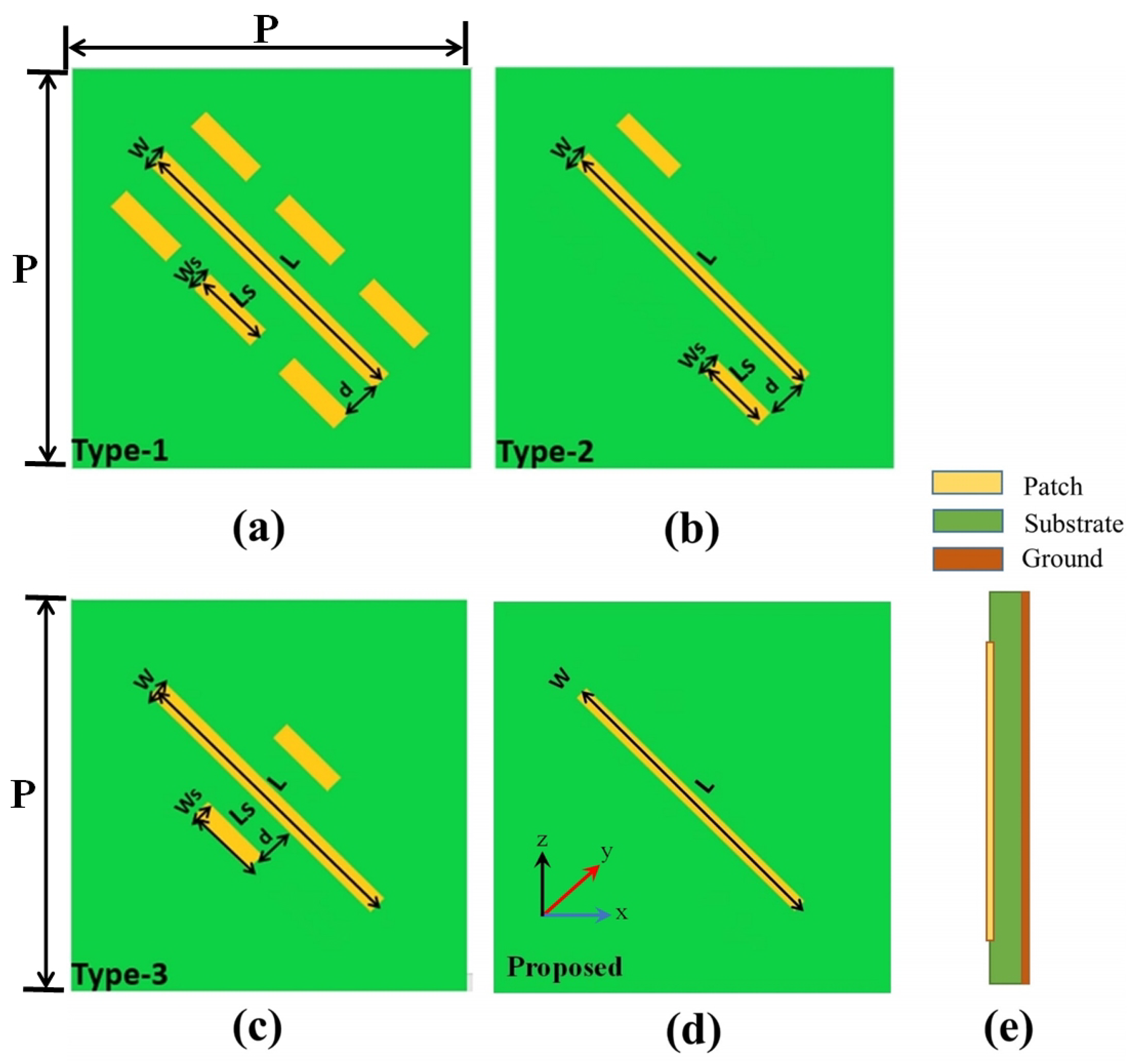
2. Design of the Metasurface
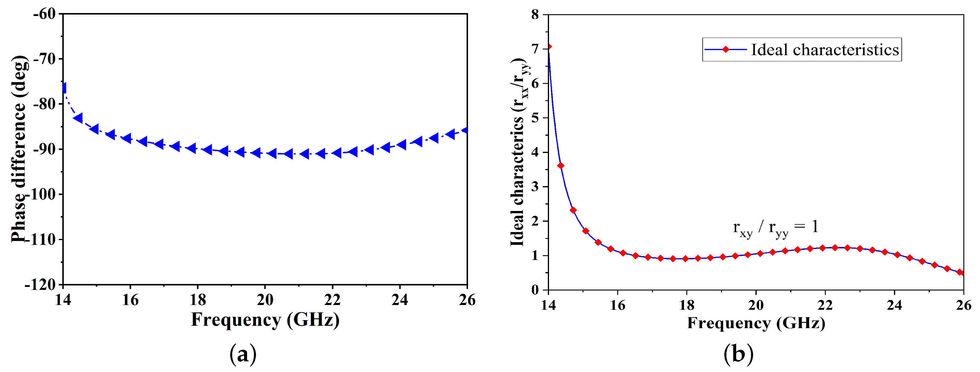
For conversion of the LTC polarization, the metasurface structure is depicted in Figure 1. The converter’s basic unit is a simple dipole shape grounded with a sheet of copper. A dielectric FR-4 isolates the dipole shape from the substrate, which has a height of h = 1.6 mm, while the relative permittivity ( ε r ) and the tangent loss ( tan δ ) are 4.5 and 0.025, respectively. The copper-grounded plane of the bottom is entirely reflective. The thickness of the copper patch (t) is measured to be 0.017 mm, while the electrical conductivity ( σ ) is 5.8 × 10 7 S/m. The additional unit cell properties are listed in Figure 1, i.e., P = 6.00 mm, L = 5.6 mm, W = 0.2 mm, Ls = 1.4 mm, Ws = 0.2 mm, and d = 0.4 mm.
The design of the unit cell was carried out through a series of sequential steps. First, we considered a simple metallic line resonator with six small dipoles on both sides, as shown in Figure 2a, in the frequency range of 15.582 to 24.154 GHz. We examined the reflection response of this design when subjected to an incident wave with y-polarization. The results for the reflection coefficient are depicted in Figure 2a. Furthermore, we optimized the patch structure by removing all the small dipoles except for two dipoles at the endpoint in the frequency range 15.623 to 24.297 GHz, as shown in Figure 2b. Through further optimization, we replaced the two small dipoles at the center of the main dipole, as shown in Figure 2c. The proposed conversion occurred within frequencies ranging from 15.41 to 25.23 GHz, as illustrated in Figure 2d. We removed all the small dipoles, retaining only one large dipole. Although the results were nearly identical to the other optimized designs in Figure 2a–c, the structure and design shown in Figure 2d were adequate, efficient, and simple. We performed a series of simulations utilizing the CST MWS software to assess the design effectiveness in terms of the LTC polarization conversion efficiency. The unit cell of the boundary conditions defined the x- and y-axes, whereas a Floquet port provided the z-axis. When an incoming plane wave of y- or x-polarization strikes the top of the presented structure, the y-polarized wave can be expressed as ( E y i = E y i e ^ y ) while the x-polarized wave can be expressed as ( E x i = E x i e ^ x ) . Following the wave striking the surface, the reflected y-incident wave can be mathematically written as E r = E x r e ^ x + E y r e ^ y = r x y exp ( j φ x y ) E y i e ^ x + r y y exp ( j φ y y ) E y i e ^ y , where r y y = E y r / E y i and r x y = E x r / E y i are the ratios of the reflection of y-to-y and y-to-x in terms of the co- and cross-polarization, respectively, while φ y y and φ x y describe the subsequent phases. The y- and x-axes have unit vectors denoted by e ^ y , e ^ x . The letter i represents the incident wave, while r indicates the reflection wave. Under specific conditions, the incident wave can be transformed from linear to circular conversion, changing its polarization state when r y y = r x y Δ φ x y = φ y y φ x y = ± 90 ° = 2 k π ± π π 2 2 , w h e r e  k = 0 , 1 , 2 ) .
The magnitudes of the simulated r y y and r y x reflection coefficients of the dipole shape are illustrated in Figure 3. Within the frequency range 15–25 GHz, as Figure 3a demonstrates, the phase difference of the r y y and r y x for the dipole shape is −90 ° . Furthermore, Figure 3b demonstrates that the r y y and r x y polarization ratio is approximately equal to 1 in the frequency range between 15.41 and 25.23 GHz, where the metasurface displays ideal characteristics. If the ratio of the orthogonal co-/cross-polarized components r y y and r x y lies within 1, and the relative phase difference is also equal to ±90 ° , the operation of the circular polarizer is adequate. The frequency range between 15.41 and 25.23 GHz provides nearly optimal circular polarization conversion, which is worth noting. These ideal characteristics are responsible for the low substrate loss, equal power distribution, and ±90 ° relative phase difference among the two orthogonal co-/cross-reflection components, as shown in Figure 3b.
Previous simulations indicate that the behavior is reversed when the y-polarized incident wave is present, as it closely resembles a RHCP wave within the frequency range between 15.41 and 25.23 GHz. Using a promising technique, the AR is presented to examine the LTC PC. After the reflection of the wave from the surface, the AR was computed using the simulation data presented in Figure 2d and Figure 3a. The AR is stated as: A R = r x y 2 + r y y 2 + a / r x y 2 + r y y 2 a 1 2 , where a = r x y 4 + r y y 4 + 2 r x y 2 r y y 2 cos 2 Δ φ y x . As shown in Figure 4a, the AR of a simple dipole shape, calculated over a range of frequencies, is considerably less than 3 dB in the ultra-wideband (15.41–25.23 GHz). This ultra wide-band has a bandwidth related to 49.1% (FBW (%) = f h f 1 / f 0 × 100 ) employed to perform the polarization from the LTC, whereas f h is the higher frequency, f 1 is the lower frequency, and f 0 is the reference frequency. Furthermore, the AR remains below 2 dB, showing that the polarization converter’s PCR is greater than 98%.
Using the above-simulated results, the reflection coefficients of the LTC PC, the polarization extinction ratio (PER), and the polarization conversion ratio (PCR) are computed, where LHCP, r L H C P y = 1 2 r x y i r y y r R H C P y = 1 2 r x y + i r y y , PCR = r R H C P y 2 / ( r R H C P y 2 + r R H C P y 2 ) , PER = 20 log r x y / r y y . The efficiency of the cross-polarization conversion can be determined with the use of PCR. Figure 4b depicts the magnitudes of the proposed dipole shape r L H C P y and r R H C P y . The r R H C P y magnitude in the 3-dB range is considered extremely close to 0 dB, indicating that the wave reflected along with the y-polarized incidence has nearly been changed into an RHCP wave. Furthermore, when assessing the conversion efficiency, it is crucial to consider the PCR and the PER as two significant factors. The PER among the r R H C P y and r L H C P y is computed to find out the efficiency of the circular polarization. It is important to maintain a PER value of + 20 dB, RHCP, and a PER value of 20 dB in the case of L H C P to obtain an identical magnitude and a phase difference ( Δ φ y x ) equal to 90 ° . Figure 5a shows that the PCR of the dipole shape is greater than 98% in the frequencies ranging from 14 to 24 GHz. In Figure 4a, it is evident that the frequency bands ranging from 15.41 to 25.23 GHz satisfy the PER criterion. In relation to the PCR and PER frequency bands, occupying 49.1% of the 3 dB AR band (16–24 GHz), the proposed polarization converter demonstrates a significant improvement in efficiency. In conclusion, the proposed metasurface displays notable effectiveness and a broad frequency range for converting an incident y-polarized wave into a circularly polarized one.

3. Stokes Theorem

The proposed converter’s LTC polarization conversion efficiency is determined using the Stokes parameters [26].
S 0 = r y y 2 + r x y 2
S 1 = r y y 2 r x y 2
S 2 = 2 r x y r y y cos Δ φ x y
S 3 = 2 r x y r y y sin Δ φ x y
In accordance with the defined concepts of the Stokes parameters, the mathematical representation for determining the normalized ellipticity can be written as e = S 3 / S 0 = ± 1. The normalized ellipticities of e = S 3 / S 0 = + 1 and e = S 3 / S 0 = 1 for the reflected wave indicate LHCP and RHCP, respectively. Figure 3 and Equations (1)–(4) can be used to calculate the frequency-dependent normalized elliptic ratio (ellipticity), as shown in Figure 5b. In the frequency range 15.41–25.23 GHz, the normalized ellipticity is about −1, indicating that the reflected wave is RHCP. To provide a more comprehensive explanation of the efficacy of the circular polarization, we establish the relationships tan 2 α = S 2 / S 1 and sin 2 β = S 3 / S 0 , where the “ α ” represents the rotational angle of the polarization, specifically referred to as the azimuthal angle. On the other hand, the “ β ” denotes the elliptical angle. Additionally, Figure 5b demonstrates that the elliptical angle in the frequency band (15.41–25.23 GHz) is −45 ° , showing that the reflected electromagnetic wave is RHCP.

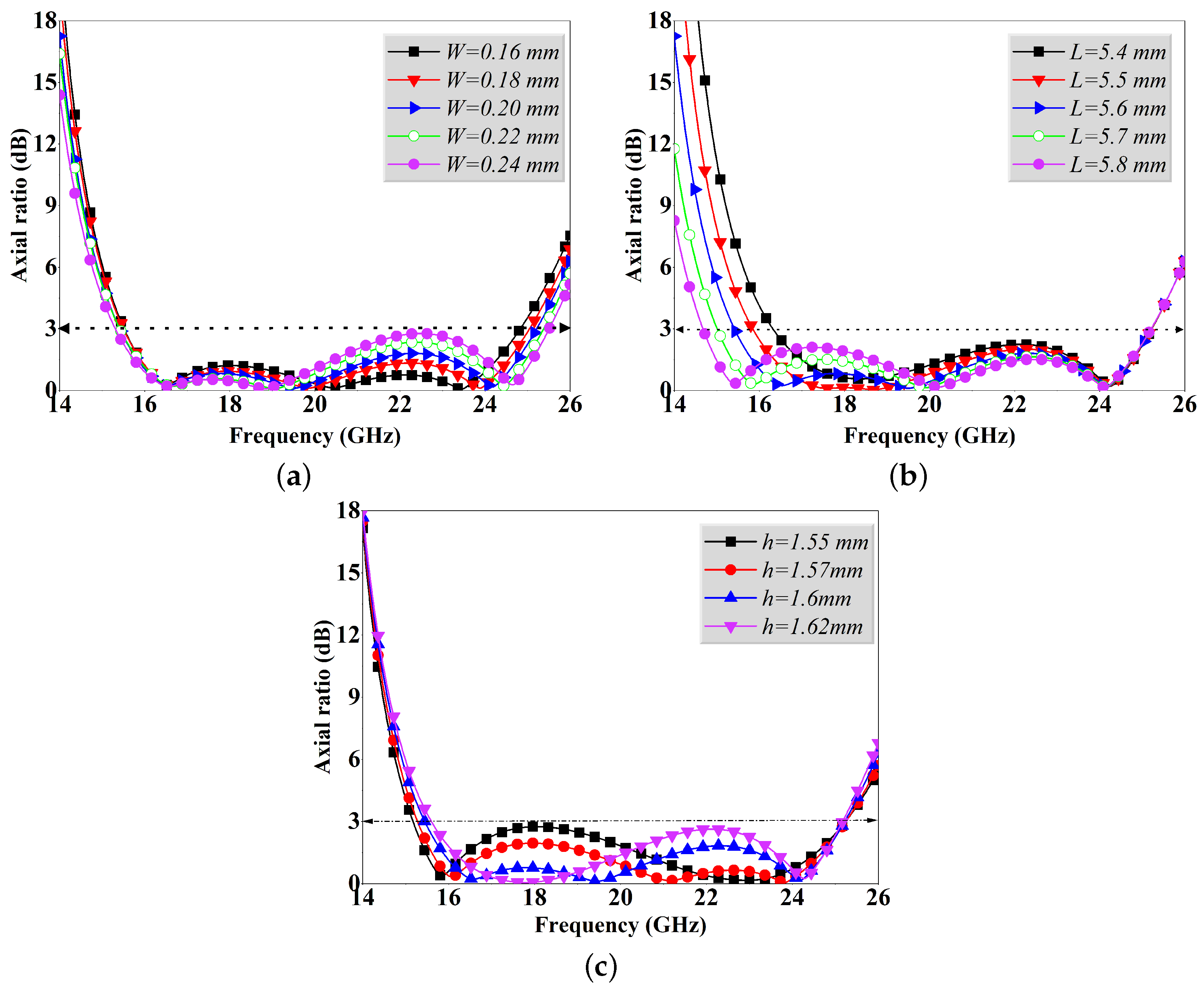
4. Parameters Analysis

In order to obtain a better understanding of the design, we investigated by changing the parameters ( α , W, and L) for a simple dipole shape patch and observing how the unit cell responded.
Figure 6 depicts the parameters in detail. This study provides a comprehensive analysis of the various parameter tests, focusing on the impact of individual parameter variations on the AR of the suggested unit cell. The discussion considers the specific details of each test, highlighting the effects of altering a single parameter while keeping all other parameters constant. Figure 6 displays the results of the parametric AR calculations that were performed. Both the W and L parameters have an impact on the resonance of the AR at higher frequencies, as illustrated in Figure 6a,b. Modifying these parameters has a marginal effect on improving the AR of the −3 dB bandwidth at higher frequencies. These W and L parameters are selected from different ranges; the first range covers from 0.16 mm to 0.24 mm, and the second range covers from 5.4 mm to 5.8 mm, respectively, in order to achieve a compromise for the 3-dB AR. To enhance the optimization of the unit cell structure, we performed a number of simulations by altering the upper dielectric layer’s thickness h within the range 1.55 mm to 1.62 mm. The simulation results obtained, as depicted in Figure 6c, demonstrate that the proposed h value of 1.6 mm shows a very good magnitude below −3 dB. Based on the preceding explanation, the proposed metasurface shows outstanding performance in the conversion of circular polarization.

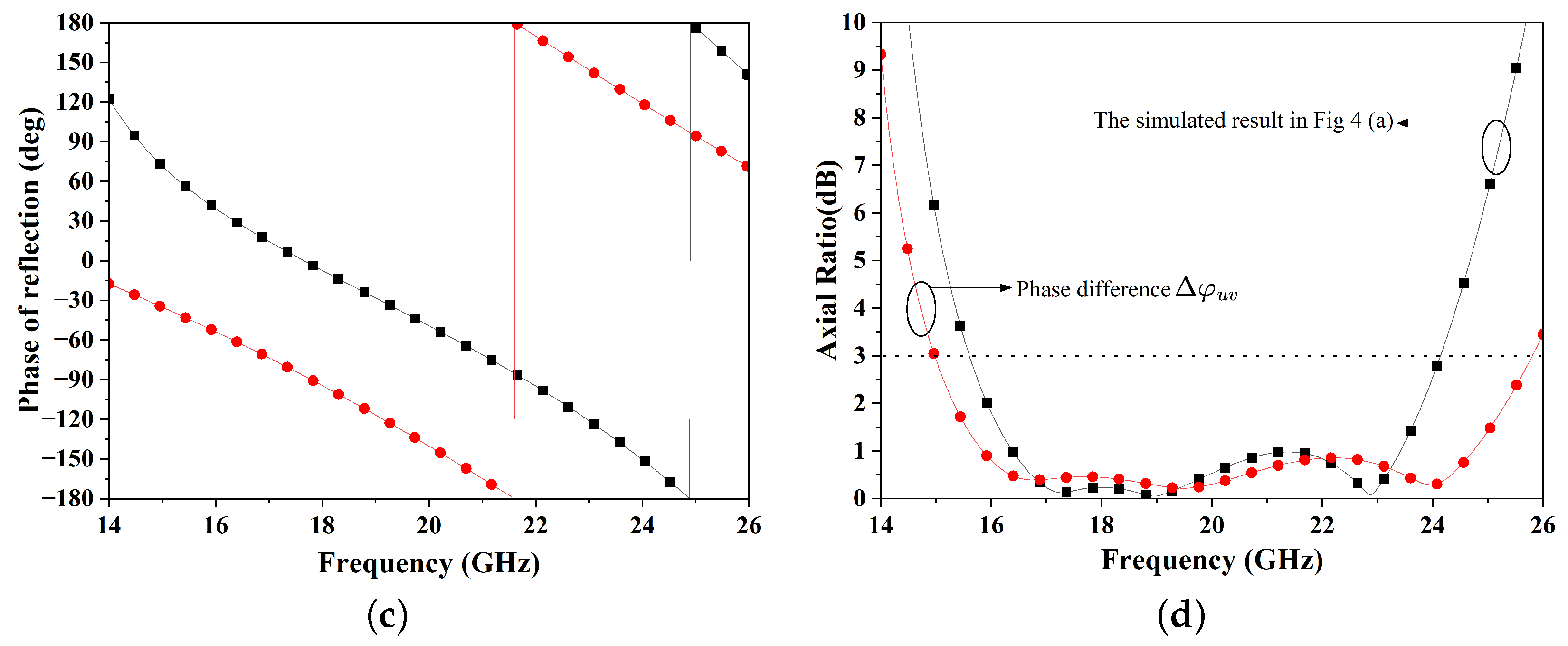
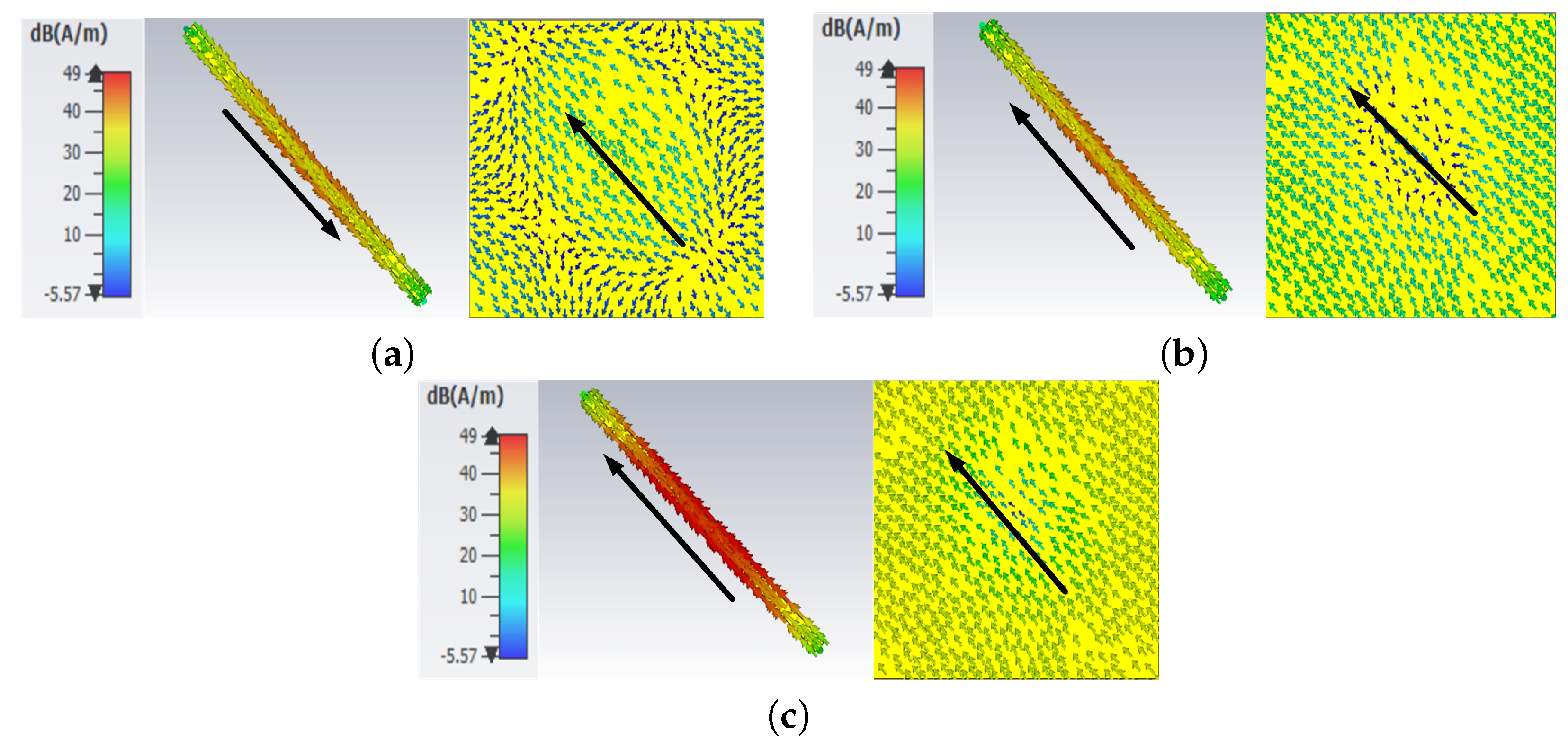
5. Theoretical Analysis

In order to establish a comprehensive physical configuration, we conducted in-depth theoretical research. In the UV local coordinate, the R I i n (reflection matrix) at LP incidence is:
R I i n = 0 r u u r v v 0
After deriving similarly for the x- and y-polarized incidence, R I i n is calculated in the X Y Cartesian coordinate system as follows:
R I i n = r y x r x x r y y r x y = 1 2 r u u 1 1 + e j Δ φ u v e j Δ φ u v 1 + 1 e j Δ φ u v e j Δ φ u v
According to Equation (6), the subsequent equation can be determined.
r y y r x y = r x x r y x = 1 + e j Δ φ u v 1 e j Δ φ u v = e j Δ φ u v / 2 + e j Δ φ u v / 2 e j Δ φ u v / 2 e j Δ φ u v / 2
In addition, the relationship r y y / r x y = r x x / r y x appears in Equation (7). Equation (7) indicates that the ratio of the r y y / r x y or r x x / r y x polarized reflected components at the y- and x-polarized incidents are constantly identical, which suggests that an anisotropic metasurface alters a y-incident polarized wave into an L H C P / R H C P reflected wave. When the exciting wave is x-polarized, the LP-CP polarization can be comprehended simultaneously. Additionally, the x-polarized incidence wave transforms into an L H C P / R H C P reflected wave. Furthermore, the magnitudes of r y y , r x x and r x y , r y x can be described as follows using Equation (7):
r y y = r x x = ( 1 + cos Δ φ u v ) / 2 r x y = r y x = ( 1 cos Δ φ u v ) / 2
When Δ φ u v = 0 ° , Equation (8) denotes that the polarization state of the incident/reflected wave will be the same. When Δ φ u v = 180 ° , however, r y y = r x x = 0 to accomplish an ideal cross-polarization. Also, the reflected polarized wave will be elliptically polarized when the Δ φ u v 0 ° or ± 180 ° and the axial ratio of the reflected wave can be defined as follows:
A R = 1 ± cos Δ φ u v / 1 cos Δ φ u v
According to Equation (9), the selection process of the subtraction ( ) and addition (+) symbols ensures that AR will never be less than 1.0. According to Equation (8), the reflected wave’s AR is roughly close to 1.0 at Δ φ u v = 90 ° , indicating an ideal linear-to-circular polarization converter. Due to minimal dielectric loss, the incident and reflected x- and y-polarized EM waves can be described as synthesis waves with u- and v-incident polarized components of equal amplitude. To identify the fundamental mechanism of the LP-CP polarization converters, we used the conclusions of the previous research to simulate a prospective polarization reflective metasurface using the v- and u-polarized incidence.
Figure 7a displays the simulated phase difference regarding r u u and r v v . Figure 7b,c, illustrate further simulated results, including the reflective amplitude r u u and r y y of the proposed polarizer broadband and its phase φ u u and φ v v to confirm the fundamental cause. The proposed polarization converter has a negligibly low dielectric loss, as evidenced by all the frequency amplitudes being close to 1.0, as illustrated in Figure 7b. The Δ φ u v is + 90 ° over 14 to 26 GHz in the frequency band, according to the phase fluctuation rate, illustrated in Figure 7c. Finally, Figure 7d illustrates the calculated AR based on the phase difference Δ φ u v obtained in Figure 7a using Equation (9). The anticipated AR is closely compatible with Figure 4a and Figure 7d.
The distribution of the surface currents for LTC PC on both the metasurface structure and the ground plane of the unit cell is analyzed to understand the underlying physical mechanism behind the conversion. In Figure 8a–c, three plasmonic resonances (at 16.5 GHz, 19.5 GHz, and 24 GHz) are observed as a result of the interaction between the parallel and anti-parallel currents on the pattern layer (top layer) and the ground layer (bottom layer). The anti-parallel currents on the top and bottom layers lead to a strong magnetic resonance. In Figure 8a,c, the resonances at 19.5 GHz and 24 GHz are attributed to the intense currents along the outer edges (lengths) of the arrows, while the currents along the widths of the arrows cause the resonance at 16.5 GHz in Figure 8a. When the incident wave is y-polarized, the reflection of the RHCP waves occurs as the angle shifts from + 90 ° to 90 ° , and vice versa. The presence of coupling effects among both metallic patches contributes to the greater stability of RHCP conversion compared to LHCP conversion. The findings of the study suggest that these elements reveal the reasons behind the attainment of outstanding performance and the ultra-wideband LTC polarization conversion. The proposed design and the state of the art as already published are compared in Table 1.

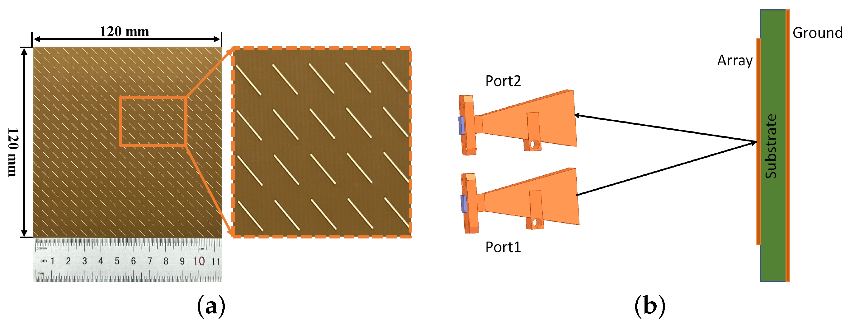
6. Experimental Work

With the aim of verifying the accuracy of the numerical simulation outcomes, a physical prototype of the proposed polarization rotator was fabricated using a 120 mm × 120 mm × 1.6 mm FR-4 sheet.
Subsequently, a series of experimental measurements were performed. The prototype, illustrated in Figure 9a, was fabricated using well-known PCB techniques. The sheet underwent selective etching, forming a well-defined pattern of 20 mm × 20 mm unit cells on one side while keeping the metallic cladding unchanged on the other side. To determine both the co-polarized and cross-polarized reflection coefficients, we placed the fabricated design in front of two horn ports (antennas): port 1 for transmission and port 2 for receiving the reflection of the electromagnetic waves. The amplitude and phase of the reflected signal from the metasurface were obtained by connecting the ports to a vector network analyzer. The measurement setup is illustrated in Figure 9b. To obtain the co-polarized reflection coefficients, the two ports were aligned in the same orientation, either horizontally or vertically. Conversely, for measuring the cross-polarized reflection coefficients, the ports were set in a perpendicular configuration to one another. The results obtained from the measurements and simulations of an incident wave for the x-polarized situation are shown in Figure 9c,d. Figure 9c presents the magnitude of both the co-polarized as well as the cross-polarized reflection coefficients, while Figure 9d shows the AR. Both the simulated and measured AR consistently remain below 3 dB within the frequency range 15.41–25.23 GHz, showing reasonable agreement. The slight variations may be attributed to fabrication imperfections and experimental tolerances.

7. Conclusions

This paper proposes a simple reflective dipole-shaped ultra-wideband LTC polarization converter. The proposed polarization converter successfully performed ultra-wideband LTC conversions and achieved an efficiency of 98% for frequencies ranging from 15.41 to 25.23 GHz. The performance of the proposed design was verified through simulation and fabrication. Moreover, a complete theoretical analysis was carried out to gain insight into the conversion of the LTC polarization. The analysis revealed that the phase difference between the reflection coefficients ± 90 ° for the v- and u-polarized incidences played a vital role in accurately predicting the resulting AR of the reflected wave. The efficiency of the LTC conversion increased when the phase difference reached ± 90 ° . The proposed simple dipole shape converter works in ultra-wideband, which shows its efficacy compared to the state-of-the-art single-layer polarization converters. The converter has substantial potential, especially in the context of antenna design.

Author Contributions

Paper writing—original draft preparation, B.H.; writing—review and editing, J.Z., A.M. and M.I.; methodology, B.H.; software, B.H.; formal analysis, B.H. and A.M.; validation, B.H., S.A. and A.K.; data curation, M.I.; investigation, S.A. and A.K. All authors have read and agreed to the published version of the manuscript.

Funding

This work was supported by the National Natural Science Foundation of China (Grant No. 62271063), the National Key Laboratory of Science and Technology on Vacuum Electronics, and the Director Fund of the Beijing Key Laboratory of Space-ground Interconnection and Convergence.

Data Availability Statement

Data are contained within the article.

Conflicts of Interest

The authors declare no conflicts of interest.

References

  1. Luo, X. Engineering optics 2.0: A revolution in optical materials, devices, and systems. ACS Photonics 2018, 5, 4724–4738. [Google Scholar] [CrossRef]
  2. Fahad, A.K.; Ruan, C.; Nazir, R.; Hassan, B. Transmissive Polarizer Metasurfaces: From Microwave to Optical Regimes. Nanomaterials 2022, 12, 1705. [Google Scholar] [CrossRef] [PubMed]
  3. He, Q.; Sun, S.; Xiao, S.; Zhou, L. High-efficiency metasurfaces: Principles, realizations, and applications. Adv. Opt. Mater. 2018, 6, 1800415. [Google Scholar] [CrossRef]
  4. Jorwal, S.; Dubey, A.; Gupta, R.; Agarwal, S. A Review: Advancement in Metamaterial Based RF and Microwave Absorbers. Sens. Actuators A Phys. 2023, 354, 114283. [Google Scholar] [CrossRef]
  5. Santonocito, A.; Patrizi, B.; Toci, G. Recent Advances in Tunable Metasurfaces and Their Application in Optics. Nanomaterials 2023, 13, 1633. [Google Scholar] [CrossRef]
  6. Tumakov, D.; Chikrin, D.; Kokunin, P. Miniaturization of a Koch-type fractal antenna for Wi-Fi applications. Fractal Fract. 2020, 4, 25. [Google Scholar] [CrossRef]
  7. Li, A.; Singh, S.; Sievenpiper, D. Metasurfaces and their applications. Nanophotonics 2018, 7, 989–1011. [Google Scholar] [CrossRef]
  8. Zhang, Z.; Wang, J.; Fu, X.; Jia, Y.; Chen, H.; Feng, M.; Zhu, R.; Qu, S. Single-layer metasurface for ultra-wideband polarization conversion: Bandwidth extension via Fano resonance. Sci. Rep. 2021, 11, 585. [Google Scholar] [CrossRef]
  9. Khan, M.I.; Khalid, Z.; Tahir, F.A. Linear and circular-polarization conversion in X-band using anisotropic metasurface. Sci. Rep. 2019, 9, 4552. [Google Scholar] [CrossRef]
  10. Li, J.; Liu, J.; Yue, Z.; Li, J.; Zheng, C.; Yang, F.; Li, H.; Zhang, Y.; Zhang, Y.; Yao, J. Polarization variable terahertz metasurface along the propagation path. Fundam. Res. 2023, in press. [CrossRef]
  11. Wu, P.C.; Sokhoyan, R.; Shirmanesh, G.K.; Cheng, W.H.; Atwater, H.A. Near-Infrared Active Metasurface for Dynamic Polarization Conversion. Adv. Opt. Mater. 2021, 9, 2100230. [Google Scholar] [CrossRef]
  12. Khan, S.; Eibert, T.F. A dual-band metasheet for asymmetric microwave transmission with polarization conversion. IEEE Access 2019, 7, 98045–98052. [Google Scholar] [CrossRef]
  13. Ahmed, A.; Cao, Q.; Khan, M.I.; Sajjad, M.; Ahmed, F. An ultra-thin multifunctional chiral metasurface with asymmetric transmission, cross-polarization conversion, and circular dichroism for Ku-and K-band applications. J. Phys. D Appl. Phys. 2023, 57, 035001. [Google Scholar] [CrossRef]
  14. Cui, Z.; Xiao, Z.; Chen, M.; Lv, F.; Xu, Q. A transmissive linear polarization and circular polarization cross polarization converter based on all-dielectric metasurface. J. Electron. Mater. 2021, 50, 4207–4214. [Google Scholar] [CrossRef]
  15. Doumanis, E.; Goussetis, G.; Gomez-Tornero, J.L.; Cahill, R.; Fusco, V. Anisotropic impedance surfaces for linear to circular polarization conversion. IEEE Trans. Antennas Propag. 2011, 60, 212–219. [Google Scholar] [CrossRef]
  16. Rashid, A.; Murtaza, M.; Zaidi, S.A.A.; Zaki, H.; Tahir, F.A. A single-layer, wideband and angularly stable metasurface based polarization converter for linear-to-linear cross-polarization conversion. PLoS ONE 2023, 18, e0280469. [Google Scholar] [CrossRef]
  17. Fu, X.; Liang, H.; Li, J. Metalenses: From design principles to functional applications. Front. Optoelectron. 2021, 14, 170–186. [Google Scholar] [CrossRef]
  18. Gao, Z.; Shi, Y.; Li, M.; Song, J.; Liu, X.; Wang, X.; Yang, F. Tunable extraordinary optical transmission with graphene in terahertz. ACS Omega 2021, 6, 29746–29751. [Google Scholar] [CrossRef]
  19. Wang, H.B.; Cheng, Y.J.; Chen, Z.N. Wideband and wide-angle single-layered-substrate linear-to-circular polarization metasurface converter. IEEE Trans. Antennas Propag. 2019, 68, 1186–1191. [Google Scholar] [CrossRef]
  20. Gao, X.; Li, K.; Wu, X.; Xue, C.; Wang, G.; Xie, X.; Qin, M. Ultra-wideband linear-to-circular polarizer realized by bi-layer metasurfaces. Opt. Express 2022, 30, 18392–18401. [Google Scholar] [CrossRef]
  21. Zhang, X.; Ye, H.; Zhao, Y.; Zhang, H. Linear-to-circular polarization converter with adjustable bandwidth realized by the graphene transmissive metasurface. Plasmonics 2022, 17, 1079–1089. [Google Scholar] [CrossRef]
  22. Lin, B.Q.; Lv, L.T.; Guo, J.X.; Wang, Z.L.; Huang, S.Q.; Wang, Y.W. Ultra-wideband linear-to-circular polarization conversion metasurface. Chin. Phys. B 2020, 29, 104205. [Google Scholar] [CrossRef]
  23. Cerveny, M.; Ford, K.L.; Tennant, A. Reflective switchable polarization rotator based on metasurface with PIN diodes. IEEE Trans. Antennas Propag. 2020, 69, 1483–1492. [Google Scholar] [CrossRef]
  24. Qin, Z.; Li, Y.; Wang, H.; Wan, W.; Li, C.; Zhu, Z.; Cheng, Y.; Li, S.; Chen, H.; Wang, J.; et al. Polarization meta-converter for dynamic polarization states shifting with broadband characteristic. Opt. Express 2022, 30, 20014–20025. [Google Scholar] [CrossRef] [PubMed]
  25. Bikkuri, S.D.P.; Alapati, S. Design of Low Profile Multiband Reflective Polarization Converter for Both Linear and Circular Polarized Waves. Prog. Electromagn. Res. Lett. 2021, 97, 61–68. [Google Scholar] [CrossRef]
  26. Zhang, B.; Zhu, C.; Zhang, R.; Yang, X.; Wang, Y.; Liu, X. Ultra-Broadband Angular-Stable Reflective Linear to Cross Polarization Converter. Electronics 2022, 11, 3487. [Google Scholar] [CrossRef]
  27. Wang, J.; Yang, R.; Ma, R.; Tian, J.; Zhang, W. Reconfigurable multifunctional metasurface for broadband polarization conversion and perfect absorption. IEEE Access 2020, 8, 105815–105823. [Google Scholar] [CrossRef]
  28. Long, F.; Yu, S.; Kou, N.; Zhang, C.; Ding, Z.; Zhang, Z. Efficient broadband linear polarization conversion metasurface based on%-shape. Microw. Opt. Technol. Lett. 2020, 62, 226–232. [Google Scholar] [CrossRef]
  29. Feng, Q.Y.; Yan, D.X.; Li, X.J.; Li, J.N. Realization of absorption, filtering, and sensing in a single metamaterial structure combined with functional materials. Appl. Opt. 2022, 61, 4336–4343. [Google Scholar] [CrossRef]
  30. Ahmed, F.; Hassan, T.; Tamoor, T.; Shoaib, N. A Multi-Functional Metasurface for Polarization Transformation Applications. In Proceedings of the 2020 IEEE International Symposium on Antennas and Propagation and North American Radio Science Meeting, Toronto, ON, Canada, 5–10 July 2020; IEEE: New Yrok, NY, USA, 2020; pp. 861–862. [Google Scholar]
  31. Zhao, J.; Li, N.; Cheng, Y. All-dielectric InSb metasurface for broadband and high-efficient thermal tunable terahertz reflective linear-polarization conversion. Opt. Commun. 2023, 536, 129372. [Google Scholar] [CrossRef]
  32. Wu, J.; Wang, X.; Xiao, H.; Wang, Y.; Fan, Z.; Zhang, H. A wide-incidence-angle insensitive multi-polarization converter based on reflective metasurface. J. Phys. D Appl. Phys. 2023, 56, 415103. [Google Scholar] [CrossRef]
  33. Kamal, B.; Chen, J.; Yingzeng, Y.; Ren, J.; Ullah, S.; Khan, W.U.R. High efficiency and ultra-wideband polarization converter based on an L-shaped metasurface. Opt. Materials Express 2021, 5, 1343–1352. [Google Scholar] [CrossRef]
  34. Jiang, Y.; Wang, L.; Wang, J.; Akwuruoha, C.N.; Cao, W. Ultra-wideband high-efficiency reflective linear-to-circular polarization converter based on metasurface at terahertz frequencies. Opt. Express 2017, 25, 27616–27623. [Google Scholar] [CrossRef] [PubMed]
  35. Majeed, A.; Zhang, J.; Awan, Z.A.; Memon, S.; Ishfaq, M.; Wang, C. A high-efficiency dual-band linear-to-circular polarization converter based on rectangular-slot reflective metasurface. Appl. Sci. 2022, 12, 9172. [Google Scholar] [CrossRef]
  36. Zheng, Q.; Guo, C.; Ding, J. Wideband metasurface-based reflective polarization converter for linear-to-linear and linear-to-circular polarization conversion. IEEE Antennas Wirel. Propag. Lett. 2018, 17, 1459–1463. [Google Scholar] [CrossRef]
  37. Wu, J.L.; Lin, B.Q.; Da, X.Y.; Wu, K. A linear-to-circular polarization converter based on I-shaped circular frequency selective surfaces. Chin. Phys. B 2017, 26, 094201. [Google Scholar] [CrossRef]
  38. Ahmed, F.; Khan, M.I.; Tahir, F.A. A multifunctional polarization transforming metasurface for C-, X-, and K-band applications. IEEE Antennas Wirel. Propag. Lett. 2021, 20, 2186–2190. [Google Scholar] [CrossRef]
Figure 1. Geometry of the proposed dipole metasurface with structural parameters. (a) A large dipole surrounds six small dipoles. (b) The large dipole is inserted between two smaller dipoles at the endpoint. (c) A large dipole is surrounded by two smaller dipoles at the center. (d) Simple large dipole. (e) Side view.
Electronics 13 00352 g001
Figure 2. The simulation results of co− ( r x x and r y y ) and cross− ( r x y and r y x ) polarization of the simple dipole shape. (a) Type-1. (b) Type-2. (c) Type-3. (d) Proposed metasurface.
Electronics 13 00352 g002
Figure 3. (a) Simulated result of the proposed metasurface of the phase difference. (b) Ideal characteristic ratio.
Electronics 13 00352 g003
Figure 4. The calculated results of a dipole shape. (a) Axial ratio AR. (b) r R H C P y and r L H C P y .
Electronics 13 00352 g004
Figure 5. Reflection coefficient of LTC polarization. (a) PCR and PER. (b) The elliptical angle and ratio.
Electronics 13 00352 g005
Figure 6. AR calculation with respect to the different parameters. (a) W (0.16–0.24 mm), (b) L (5.4–5.8 mm), (c) h (1.55–1.62 mm).
Electronics 13 00352 g006
Figure 7. Simulation results of proposed U−V polarization. (a) Phase difference Δ φ u v with respect to frequency. (b) The magnitude ( r v v and r u u ). (c) Phase variation at different frequencies. (d) AR after reflection from the proposed surface.
Electronics 13 00352 g007aElectronics 13 00352 g007b
Figure 8. The current distribution on the proposed surface on the top and bottom using different frequencies. (a) Distribution on 16.5 Hz. (b) Distribution on 19.5 GHz. (c) Distribution on 24 GHz.
Electronics 13 00352 g008
Figure 9. (a) Fabricated sample. (b) Measurement setup. (c) The simulated and measured results of the co- and cross-polarized reflection coefficients. (d) Axial ratio.
Electronics 13 00352 g009aElectronics 13 00352 g009b
Table 1. Comparison table with reported and similar literature.
Ref.Unit
(P)
Operating
BW (GHz)
Substrate
Thickness
Type of
(PC)
PCRMode
[34]94.7–21.72LP-CPN/Asurface
current
[35]616.49–23.541.6LP-CP98N/A
[36]8.113.70–15.603.5LP-CPN/Asurface
current
[37]125.86–7.341.8LP-CPN/AN/A
[38]8.255.1–5.22LP-CPN/Asurface
current
This work615.41–25.231.6LP-CP98surface
current
Disclaimer/Publisher’s Note: The statements, opinions and data contained in all publications are solely those of the individual author(s) and contributor(s) and not of MDPI and/or the editor(s). MDPI and/or the editor(s) disclaim responsibility for any injury to people or property resulting from any ideas, methods, instructions or products referred to in the content.

