Abstract
Given power fluctuations from near-land offshore wind farms, this article designs a coordinated control strategy for cascaded hybrid DC transmission. To suppress the frequency disturbances when wind power varies, supplementary active power control schemes are proposed, in which the coordinated DC voltage control strategy is also considered in order to keep DC voltage stable when the supplementary control prompts a voltage-sourced converter overload. Simultaneously, to further improve wind farm-side AC voltage stability, a dynamic limiter is added in the coordinated control, which can make a voltage-sourced converter release more reactive power when a fault happens. Thereby, the stability of DC-side voltage and active power and AC-side frequency and voltage can all be enhanced through the proposed coordinated scheme. Finally, the electromagnetic transient model of the hybrid high-voltage direct current with renewable power is established using PSCAD X4.6.2 software, and the simulation example is carried out with the model to verify the scheme proposed in this article.
1. Introduction
Hybrid DC transmission technology based on a Line Commutated Converter (LCC) and a Modular Multilevel Converter (MMC) has great advantages in cross-regional, long-distance, large-capacity power transmission and the improvement of new energy consumption capacity [1]. It is an ideal technical solution, which can be used to break the dilemma of uneven energy distribution and achieve dual carbon targets [2,3].
Generally, the LCC converter is rectified at the sending-end side while the voltage sourced converter (VSC) is inverted at the receiving-end side [4]. With such a structure, the commutation failure of the LCC can be avoided because the VSC inverter has no such problem [5]. Meanwhile, this also can help the high-voltage direct current (HVDC) system by lowering the total cost. The classical hybrid HVDC system includes one LCC and one VSC, as usual [6]. Although this structure does achieve a certain degree of hybridity, the VSC inverter at the receiving-end side will limit the DC capacity of the system, because this design still cannot solve the inherent low-capacity defect of the VSC [7].
Thus, to increase the capacity of hybrid HVDC and realize bulk power and long-distance transmission, some researchers propose to parallel the above hybrid HVDC system; then, the rated power transferred with this structure can be doubled. Nevertheless, VSC inverters in this type of hybrid system will still limit the DC system’s efficiency, and the voltage level can be increased.
Alternatively, to further enlarge the transfer capacity of the hybrid HVDC system, the multi-terminal-style hybrid structure has been proposed. In such a structure, the sending-end-side LCC rectifier is retained, but the receiving-end-side VSC inverters are expanded to two, among several terminals. With such receiving-end-side expansion, the whole capacity of the hybrid HVDC system will no longer be limited by the VSC inverters, because their numbers have been increased to cope with the capacity of sending-side LCC rectifiers. This design can realize the initial targets, such as bulk capacity and long-distance transmission. One typical application of such a hybrid HVDC system is the Wudongde project in China [8], which China Southern Power Grid Company has now finished. However, the disadvantage of such a system is that the cost of the system will be enlarged as more VSC inverters are needed. Another important disadvantage of such a hybrid HVDC is that this type of system is actually a multi-terminal system, and the protection of a multi-terminal DC system is complex and hard to tackle. Take the Wudongde project, for example; to clear the fault at the DC side, the VSC of this project is composed of the equivalent of about half the ratio of the full-bridge IGBT, which further increases the cost of the whole system. Nevertheless, when a DC-side fault happens, the whole system will face a sudden power break-off as the full-bridge IGBTs have to cut off the faulty current loop [9].
In view of the flaws of the above hybrid HVDC system, the cascaded hybrid HVDC system has also been proposed in recent years [10]. Cascaded hybrid HVDCs are basically the same as a bipolar LCC-HVDC, except that the downside LCC inverter is replaced by a VSC inverter. This type of hybrid DC system cannot avoid the commutation failure completely [11]; the possibility of such fault can decrease sharply as the number of the LCC inverters is increased, and the downside VSC inverter can also send reactive power to support the AC-side voltage stability, as can the LCC inverters [12,13,14,15,16]. But such a design also places a limit on the transferred power due to the single VSC inverter [17].
To break through this limitation, the cascaded hybrid HVDC with multi-terminal VSC inverters was then investigated [18,19]. In this model, the downside VSC inverter is expanded to increase the whole capacity of the hybrid system. More reactive power can be generated by more VSC inverters to support the upside LCC inverter. The typical application of this kind of hybrid HVDC is the Baihetan hybrid HVDC project in China [20,21].
Although it has been applied in actual projects, the control strategy of such a hybrid DC system is relatively complex and should be clarified. However, for such an important type of DC system, a research determination of its control strategy is not enough. There are only a few papers in the literature; these have accomplished some initial work. Moreover, none of the previous research efforts have studied the coordinated control scheme while considering the power fluctuations of renewable power [22,23].
To clarify a coordinated control scheme for wind power and other renewable energy subject to power fluctuations, this paper studies the basic control characteristics of multi-terminal VSC inverter-cascaded hybrid HVDC systems and designs a coordinated control strategy to suppress wind farm power fluctuations.
This strategy includes coordinated control of the AC side and the DC side, as well as active power and reactive power. On the AC side of the system, the deviation signal determines the change in the output active power at one MMC side, which can suppress the frequency fluctuation. On the DC side of the system, the power fluctuations of the three MMCs determine whether the backup MMC inverter changes the control mode for coordinated control, which can realize the stable control of the DC voltage. In addition, dynamic limiters constrain and coordinate the output of active and reactive power, maintaining the safe and stable operation of the system.
This paper’s structure is as follows. Section 2 introduces the topology and basic control schemes of the cascaded hybrid HVDC system. Section 3 studies the coordinated control strategy of frequency disturbance when suppressing wind power fluctuations, in addition to the AC voltage stability enhancement strategy also being proposed to increase the active power support ability for wind farms in this section; Section 4 verifies the analysis above based on PSCAD X4.6.2 software. Finally, Section 5 concludes this article.
2. The Cascaded Hybrid HVDC System
2.1. Cascaded Hybrid HVDC System’s Topology
Figure 1 presents a real cascaded hybrid HVDC project. The project’s beginning is Sichuan Province of China, and the end is in the Jiangsu Province of China. And the distance of HVDC is more than 2000 km. This HVDC system boasts a substantial capacity in the DC transmission system, with a bipolar capacity reaching 8000 MW.
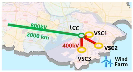
Figure 1.
The geographic location thumbnail of the cascade hybrid HVDC system.
Based on this, the simulation topology of the cascaded hybrid HVDC system is presented in Figure 1. From the figure, it can be observed that the hybrid system includes an LCC converter at the transmitter and a hybrid converter at the receiver. Compared with the typical cascaded hybrid HVDC system, the most distinctive design in this system is the inverter. It consists of three series connection VSCs, and one LCC is upward. In addition, consider a near-land wind farm and connect it to one of the VSCs. This wind farm is located in the Huangshayang sea area in the eastern part of Rudong County, with an offshore distance of approximately 61 km.
Figure 2 shows the mono-pole section of the actual project, which provides sufficient data for studying control characteristics. The system has a total capacity of 4000 MW. Specifically, the sending-end LCC converter has a capacity of 4000 MW, while the receiving-end LCC inverter has a capacity of 2000 MW. The VSC inverter has a capacity of 677 MW, and the combined capacity of the three VSC inverters is equivalent to that of one LCC inverter. The hybrid DC system operates at a rated DC voltage of 800 kV, with both the VSC inverters and LCC inverter sharing 400 kV each. For establishing the simulation model of this hybrid DC system, Table 1 provides the basic parameters.
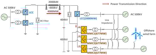
Figure 2.
The overall topology diagram of the cascaded hybrid DC system.

Table 1.
Basic parameters of the cascaded hybrid DC system’s simulation model.
2.2. Hybrid HVDC Control Scheme of the LCC Converter
The control scheme contains the strategy of rectifier control and inverter control, respectively. In comparison to traditional HVDC systems, the primary distinction in hybrid HVDC lies in the VSC inverter. Therefore, the control schemes for LCC converters remain the same as those employed in a classical two-terminal LCC-HVDC system, as depicted in Figure 3 [24].
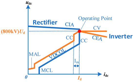
Figure 3.
The hybrid HVDC control scheme of the LCC converter.
The direct voltage and direct current curves are drawn in Figure 3, where the LCC converters’ control characteristics are described [25]. Specifically, the blue line segment represents the LCC rectifier, and the yellow line segment represents the LCC inverter, so different line segments indicate that the converters operate based on various DC voltages and current values under different control modes. The corresponding explanations for each line segment can be found in Table 2.
Table 2.
The corresponding control mode of each line segment.
2.3. Hybrid HVDC Control Schemes of the MMC Converter
MMC converter schemes consist of two components. The first component is the control mode of each converter, which comprises the active control mode and reactive power control mode. The second component is the control strategy at the system level for the three VSC inverters, as they form a multi-terminal DC grid. In such a DC grid, the control scheme at the system level can choose droop control or primary–secondary control, with each control scheme depending on the control mode of the three converters.
If the VSC operates under droop control, its DC voltage will experience fluctuations [26]. However, maintaining a constant total DC voltage is crucial for practical projects. Therefore, this article focuses on investigating the primary–secondary control strategy. Table 3 lists the control modes of each converter under the primary–secondary control. Additionally, the table specifies the reactive power control mode for each VSC, with the CV indicating constant DC voltage control, the CP representing constant active power control, and the CAC denoting constant AC voltage control.
Table 3.
Control Modes of MMC Inverters.
As for the detailed constant active power control, the control diagram is shown in Figure 4. In the diagram, Ps and Pref denote the controlled active power and its reference, Kp and Ki are the PI parameters, and idlim is the hard limiter.
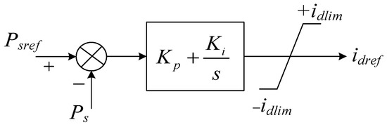
Figure 4.
The constant active power control block diagram.
3. Schemes of Coordination Control
Considering the close distance between the wind farm and the MMC inverter, coordination control schemes are proposed to prevent system frequency instability. These coordinated schemes are designed to address both active and reactive power aspects. Since the MMC inverter of the hybrid HVDC system controls the active and reactive power independently, it enables improvements in voltage stability and frequency stability simultaneously.
3.1. Control Schemes of Coordinated Active Power
3.1.1. MMC3 Supplementary Control Given Wind Power Fluctuations
Based on the previous sections of this article, it is evident that offshore wind farms will be integrated into the regional power grid near the MMC3 inverter. Considering that the local power system may not be robust enough, fluctuations in wind power can lead to frequency deviations. To address this, a supplementary active power control strategy is designed for the MMC3 side.
Figure 5 is a block diagram of supplementary control. An additional signal, Padd, generated by the power deviation ΔP or the frequency deviation Δf is added to the active power outer loop. And T is the time constant of the first-order component; Kp1 and Ki1 are the PI parameters. The DBlk indicates the deblock signal, which plays a role in the supplementary function.
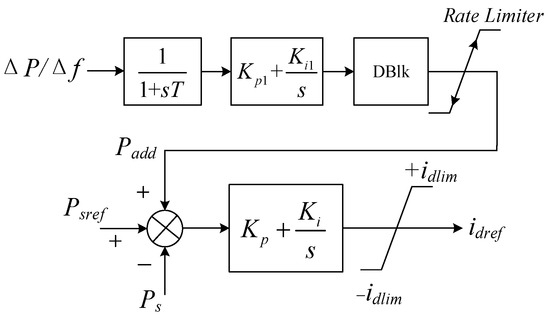
Figure 5.
The supplementary control diagram of the condition of wind power fluctuations.
The objective of the supplementary control is to control the active power of the MMC3 inverter using the input signals of power deviation ΔP or frequency deviation Δf. In this way, the frequency fluctuation on the AC side of the system is suppressed. It is important to note that these signals are obtained through measurements.
3.1.2. DC Voltage Coordination Scheme Given the Supplementary Control
The purpose of this supplementary control is to compensate for the power fluctuations from the wind farms by adjusting the active power reference of the controlled MMC3 inverter. Essentially, the power disturbance is transferred to another MMC1 inverter operating in the CV mode, in which the relatively strong system is on the MMC1 side.
However, in certain cases, the inverter may become overloaded when operating in the CV mode. Consequently, the control mode switches to the CP mode, in this way, resulting in the loss of MMC1’s ability to control the DC voltage. Therefore, this article proposes a coordination scheme for DC voltage control. Figure 6 shows the control process of this scheme. When the system finds that the original CV inverter is unable to maintain control, the responsibility of DC voltage regulation is transferred to MMC2. This scheme operates without relying on remote signals and instead utilizes local DC voltage fluctuation.
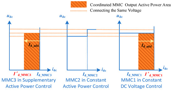
Figure 6.
The coordinated control of MMC inverters.
The aforementioned control focuses on the coordinated control of the AC side, while the following discussion pertains to the coordinated control of the DC side. As shown in Figure 6, the stable surge of DC voltage control is mainly realized through the power fluctuations of the three MMC inverters on the DC side. When the power fluctuations are too large, the control function of the fixed DC voltage station is transferred to the backup fixed DC voltage station. This ensures the stability of the DC system and is also based on in-station measurements.
This scheme determines the change in active power of the MMC3 inverter according to the frequency deviation Δf caused by wind power fluctuations. If the value of Δf is small, the active power of the MMC3 inverter remains low. Conversely, if the value of Δf is large, the active power of the MMC3 inverter increases. However, when the active power of the cascaded hybrid DC system is high, it can impact the active power of the MMC1 inverter controlled by the CV mode. To solve this problem, the MMC2 inverter serves as a backup force for CV mode control, ensuring the suitability of this strategy for varying degrees of wind power fluctuations. While improving the frequency stability of the AC system, it can also make the DC system work stably.
3.1.3. The Completed Active Coordination Scheme
According to the DC voltage control analysis above, the voltage control by the MMC and the LCC can be expressed as
The , , and are the slopes of different line segments, where the subscript of the slopes denotes the specific line segment. And the , , and are different DC voltages in different operation modes.
By adding (1) to (2) to (5) successively, the active coordination scheme can be expressed by the following equations. And Figure 7 shows them in UI curves.
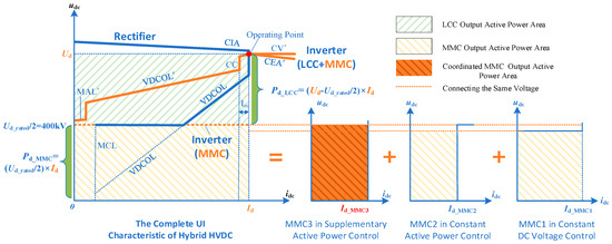
Figure 7.
The completed active coordination scheme is expressed in the UI curve.
Therefore, in the active coordination scheme, the constant DC voltage control is handled by the MMC1 inverter, which acts as the dedicated constant DC voltage station. This is because the entire multi-terminal DC system, comprising the MMC1 inverter, MMC2 inverter, and MMC3 inverter, only necessitates a single MMC station to achieve effective DC voltage balancing control.
Furthermore, the control strategy discussed in this paper does not involve the underlying control details, and hence, it is not specifically displayed. If you are interested in gaining a deeper understanding, you can refer to the citations mentioned in reference [27].
3.2. Coordinated Reactive Power Control
While the preceding section focuses on designing the active coordination scheme, it is equally important to ensure the stability of the AC voltage at the wind farm side.
3.2.1. The Dynamic Limiter
The reactive power of the VSC is determined by the reactive limiters. Typically, the limit value of the reactive control loop is fixed at 0.4 p.u. However, to enhance the VSC’s ability to generate reactive power, the implementation of dynamic limiters can be considered [28].
The dynamic limiter operates on the principle that the outer loop control current is influenced by both the active power and reactive power current, as demonstrated in Equation (10).
According to the priority type, the current limiter can be divided into three types as Figure 8 shows, namely the active current prior type, the reactive power prior type, and the equal priority type.
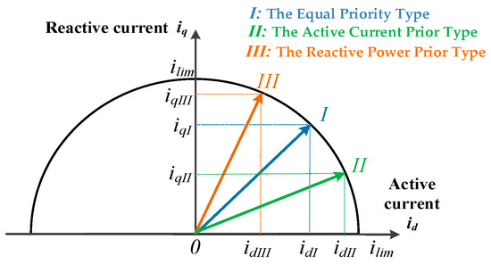
Figure 8.
Three types of current limiters.
The dynamic reactive current limiter allows for adjustable reactive limit values in situations where the AC system requires additional reactive power. This feature is defined by Equations (11) and (12).
In the above equations, the iDlim is a fixed value to make sure a minimum active power can be transferred. The specific mechanism of the dynamic limiter can be found in Figure 9 and [29].
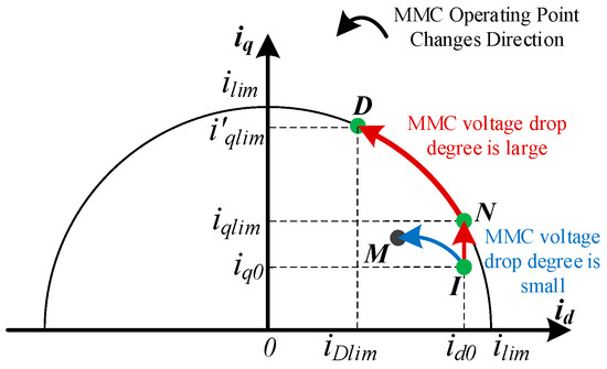
Figure 9.
The operation point changing situation with a dynamic limiter.
The converter is required to operate in a stable manner, which necessitates the implementation of a dynamic limit to constrain the power, denoted as in (12). The role of is to specify the value of reactive power in the dynamic limiter. If the is set to the commonly used value, the dynamic limiting function is not activated. However, by reducing the setting value of , the effectiveness of dynamic limiting increases. In practical engineering, is typically set to 0.4, allowing for the release of more reactive power while ensuring the minimum output of active power. This setting serves as an additional protective measure for the safe operation of the system.
3.2.2. The Coordination Scheme with the Dynamic Limiter
The coordination scheme featuring a dynamic limiter is designed as Figure 10 shows. This strategy enables a substantial increase in the reactive power output from the MMC3 with the dynamic limiter, where the Q′lim is the additional reactive power the dynamic limiter generated out. Moreover, the original active power can be shifted to the other MMC when the MMC3’s active power is suppressed, and the DC voltage can be guaranteed stably.
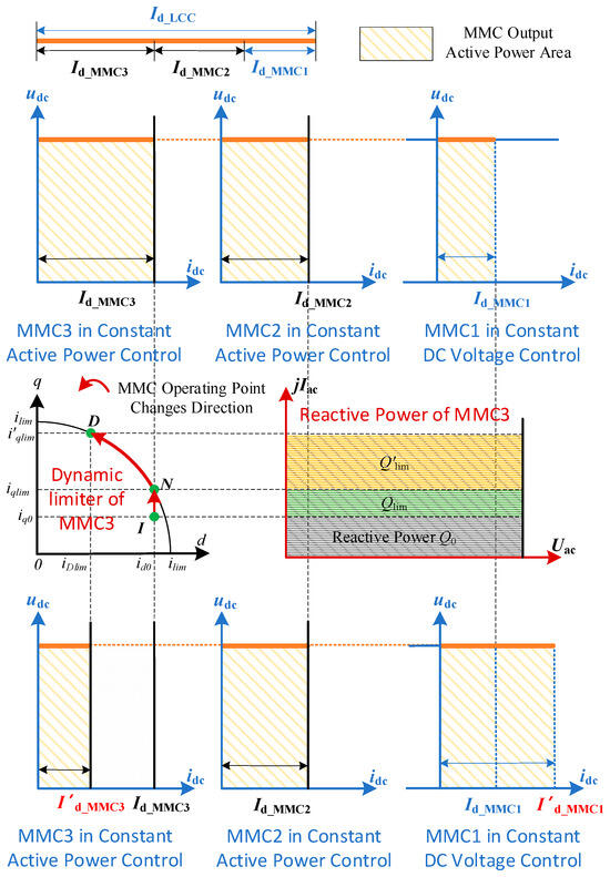
Figure 10.
The coordination scheme with a dynamic limiter.
4. Case Study
This section takes the case study as an example to set the parameters and topology of the hybrid DC system, as shown in Figure 2.
4.1. Simulations of Static UI Characteristics
To prove the correctness of the fundamental UI curves presented in Figure 7, an initial investigation is conducted into the static control characteristic of the cascaded hybrid DC system.
Specifically, the LCC rectifier and inverter are set in the CI control mode and CEA control mode, respectively. Additionally, the MMC1 operates in the CV control mode, while MMC2 and MMC3 are set to the CP control mode. The resulting simulations provide insights into various parameters, including γ, direct current, DC power, and DC voltage, which are presented in Figure 11.
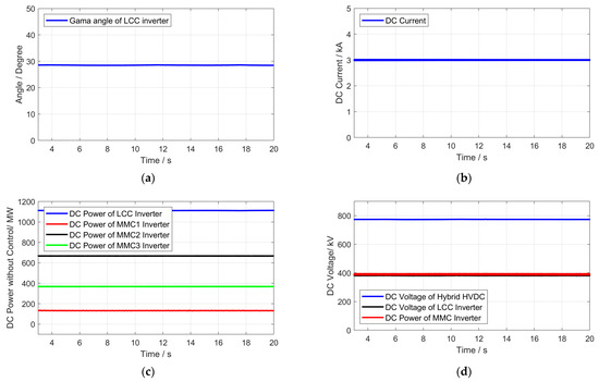
Figure 11.
The situations in static operation. (a) The extinction angle (γ) of the LCC inverters in static operation. (b) The direct current is in static operation. (c) The DC power of each inverter in static operation. (d) The voltage of the LCC and the MMC in static operation.
It is evident that each converter functions in its designated mode, with the DC voltage of the hybrid HVDC system comprising both the LCC and MMC part, each contributing 400 kV. The simulation results verify the UI curve analysis part and prove that the hybrid HVDC can operate stably.
4.2. Simulation Control of Coordinated Active Power
4.2.1. The Supplementary Control Verification When Wind Power Fluctuates
After the basic operation characteristic verification, simulations of supplementary control are implemented when the power of the offshore wind farm fluctuates, where there is supplementary control of the MMC3 inverter.
As shown in Figure 12a, the active power fluctuations from the offshore wind farms are clearly depicted. Meanwhile, Figure 12b illustrates the DC power of each inverter, highlighting that the MMC3 inverter with supplementary control effectively adjusts its output active power to compensate for the wind power fluctuations. Notably, the active power of the MMC1, which operates in the constant DC voltage control mode, also experiences fluctuations due to its role as a slack node.
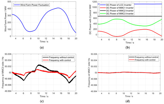
Figure 12.
The MMC1 side with constant DC voltage control. (a) Offshore wind farm active power fluctuations. (b) Add the supplementary control of the DC power. (c) The MMC3 side’s AC frequency with the supplementary control strategy. (d) The MMC1 side’s AC frequency in constant DC voltage control.
Additionally, the frequency-changing situations on the MMC3 side are presented in Figure 12c, when the wind power fluctuates. It is obvious that the frequency stability on the MMC3 side can be improved through the proposed control.
Figure 12d presents the frequency on the MMC1 side, indicating that the control strategy does not deteriorate the frequency stability, even when the MMC1’s output undergoes fluctuations due to the system’s inherent robustness.
4.2.2. Coordinated DC Voltage Control Verification Considering Supplementary Control
It is also necessary to verify the DC voltage coordinated control strategy to prevent the large fluctuation of wind power from losing the DC voltage control ability of the MMC1 inverter.
Figure 13a presents the substantial active power fluctuations originating from offshore wind farms. Figure 13b shows the DC power variations of each inverter, specifically under the combined application of supplementary power control and DC voltage coordinated control.
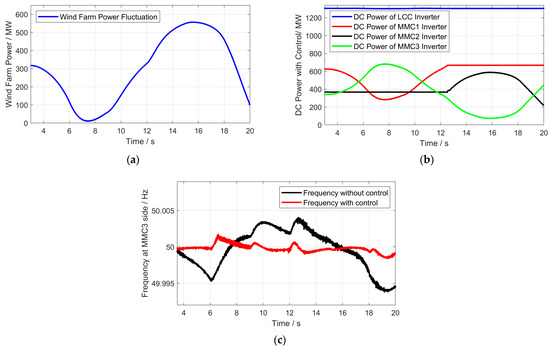
Figure 13.
In the case of the severe fluctuation of wind power, the supplementary control strategy is adopted. (a) The active power of offshore wind farms fluctuates greatly. (b) Coordinated control of DC power. (c) In the violent fluctuation of wind power, the AC frequency of the MMC3 side is controlled by a supplementary strategy.
Observing Figure 13b, it becomes apparent that wind power fluctuates greatly after 12 s, which causes the MMC1 controlled by CV overload and becomes a constant active power inverter. At 12.5 s, MMC2′s control strategy is swiftly adapted to become the inverter responsible for DC voltage control, thereby maintaining system stability and redirecting excess power fluctuations to the MMC2 side.
Figure 13c shows MMC3′s frequency side, which also proves that when wind power fluctuates violently, the disturbance can also be suppressed.
4.2.3. Stability Verification of Long-Term Supplementary Control
This simulation case spans 50 s, affording the opportunity to thoroughly validate the long-term adaptability of the control strategy. It incorporates the continuous fluctuations of wind power and carries out supplementary control verification specifically on the MMC3 side.
The long-term fluctuations of active power from offshore wind farms are shown in Figure 14a, and the DC power of each inverter is shown in Figure 14b. And the frequency-changing situations on the MMC3 side and the MMC1 side are presented in Figure 14c,d. Notably, the supplementary control on the MMC3 side proves to be effective in compensating for wind power fluctuations over extended periods, maintaining the stable frequency on both the MMC3 side and MMC1 side. This confirms the ability of this control strategy to ensure stability even during prolonged operational durations.
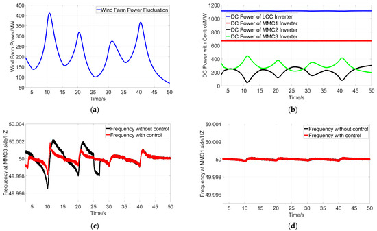
Figure 14.
The situation with long-term control. (a) Offshore wind farm active power fluctuations. (b) Add supplementary control of the DC power. (c) The MMC3 side’s AC frequency with a supplementary control strategy. (d) The MMC1 side’s AC frequency in constant DC voltage control.
It is evident that this proposed strategy has good effects across various scenarios and time scales, particularly when compared to traditional frequency control methods. This strategy can effectively handle system frequency fluctuations and facilitates the optimal utilization of renewable energy sources. When the fixed DC voltage station MMC2 inverter is invalid, the backup fixed DC voltage station MMC1 inverter can automatically control the DC voltage, which can improve the stability of both the DC and AC sides of the system.
4.3. Simulations of Dynamic Limiters
The previous sections focused on verifying the active power control component, but it is equally important to validate the coordinate reactive control strategy integrated with dynamic limiters. By adding the dynamic limiter on the MMC3 inverter, simulation results are presented from Figure 15 to Figure 16, respectively, where an external AC grounding fault happens at 5 s.
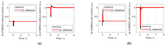
Figure 15.
The d/q axis currents of MMC3. (a) The d/q axis currents of MMC3 without the control. (b) The d/q axis currents of MMC3 with the control.
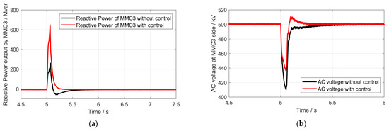
Figure 16.
Situations with and without the control. (a) The reactive power of MMC3. (b) AC voltage with and without the control.
The result indicates that the proposed strategy significantly enhances reactive power generation, which, in turn, vastly improves the stability of the AC side. This enhancement contributes to the safe and reliable operation of the near-land wind farms.
Regarding the dynamic limiter, its input is based on the frequency deviation Δf. In typical operational scenarios, the system runs stably for a long time, resulting in minimal or even zero Δf values. Additionally, a dead zone is set for Δf, ensuring that when |Δf| is less than 0.5 HZ, the controller remains inactive. Consequently, in the practical long-term applications, the introduction of the dynamic limiter does not compromise the original system performance. However, it is worth noting that prolonged operation may have some impact on equipment aging, which is inherent to the equipment itself rather than a limitation of the control strategy.
5. Conclusions
This article delves into a cascade hybrid DC coordinated control scheme in the context of wind power fluctuations. The conclusions are as follows.
- The basic control characteristics of the hybrid HVDC system are clarified. Specifically, the design of the supplementary active power control can effectively suppress frequency deviations generated within the near-land regional power grid during wind power disturbances. This mechanism redirects wind power disturbances away from the cascaded multi-infeed MMC inverters, redirecting them instead to other regional power grids. Through this process, other MMCs assume the responsibility of managing these fluctuations, ultimately enhancing the overall system stability.
- In CV control, this coordination scheme ensures the stability of the DC voltage even under the overload condition of the original VSC. This ensures that the hybrid HVDC system remains stable, while simultaneously enhancing its ability to suppress fluctuations, thus improving overall system performance.
- The dynamic limiter is remarkably effective in improving voltage stability. With the aid of this proposed limiter, a significant amount of additional reactive power can be generated, further facilitating the smooth integration of renewable energy sources into the grid.
It is worth noting that a cascaded hybrid HVDC system may encounter oscillation issues. Future research must address the broadband oscillations that these systems inherently generate, and this is a current area of our ongoing investigations.
Author Contributions
T.Z.: Conceptualization, Writing—original draft, Writing—review and editing, Software, Data curation. Q.L.: Supervision, Writing—review and editing. Y.X.: Software, Data curation. Y.Z.: Software, Data curation. D.L. (Deming Liu): Software, Data curation. D.L. (Dong Liu): Software, Data curation. All authors have read and agreed to the published version of the manuscript.
Funding
Sichuan Science and Technology Program (2023YFQ0073).
Data Availability Statement
The original contributions presented in the study are included in the article; further inquiries can be directed to the corresponding author.
Conflicts of Interest
We declare that the research was conducted in the absence of any commercial or financial relationships that could be construed as a potential conflict of interest.
Abbreviations
| Abbreviation | Full Name |
| AC | Alternating Current |
| DC | Direct Current |
| LCC | Line Commutated Converter |
| VSC | Voltage Sourced Converter |
| HVDC | High-Voltage Direct Current |
| MMC | Modular Multilevel Converter |
| LCC-HVDC | Line Commutated Converter-based High-Voltage Direct Current |
References
- Xue, Y.; Ge, F.; Zhao, Z.; Zhang, Z.; Xing, F. Control strategy for hybrid LCC-C-MMC HVDC system under AC fault at rectifier side. J. Eng. 2019, 2019, 3259–3263. [Google Scholar] [CrossRef]
- Qahraman, B. Series/Parallel Hybrid VSC-LCC for HVDC Transmission Systems. Ph.D. Dissertation, Department of Electrical and Computer Engineering, University of Manitoba, Winnipeg, MB, Canada, 2010. [Google Scholar]
- Lou, B.; Zhou, H.; Xu, Z.; Wang, S.; Xu, Y. Fault response comparison of LCC–MMC hybrid topologies and conventional HVDC topology. J. Eng. 2019, 2019, 2068–2073. [Google Scholar] [CrossRef]
- Yang, R.; Xiang, W.; Lin, W.; Wen, J. Hybrid ultra-HVDC system with LCC and cascaded hybrid MMC. J. Eng. 2019, 2019, 1112–1116. [Google Scholar] [CrossRef]
- Torres-Olguin, R.E.; Garces, A.; Molinas, M.; Undeland, T. Integration of Offshore Wind Farm Using a Hybrid HVDC Transmission Composed by the PWM Current-Source Converter and Line-Commutated Converter. IEEE Trans. Energy Convers. 2013, 28, 125–134. [Google Scholar] [CrossRef]
- Jiang, Q.; Li, B.; Liu, T.; Blaabjerg, F.; Wang, P. Study of Cyber Attack’s Impact on LCC-HVDC System With False Data Injection. IEEE Trans. Smart Grid 2023, 14, 3220–3231. [Google Scholar] [CrossRef]
- Zeng, R.; Xu, L.; Yao, L.; Finney, S.J.; Wang, Y. Hybrid HVDC for Integrating Wind Farms With Special Consideration on Commutation Failure. IEEE Trans. Power Deliv. 2016, 31, 789–797. [Google Scholar] [CrossRef]
- Rao, H.; Zhou, Y. Key technologies of ultra-high voltage hybrid LCC-VSC MTDC systems. CSEE J. Power Energy Syst. 2019, 5, 365–373. [Google Scholar] [CrossRef]
- Haleem, N.M.; Rajapakse, A.D.; Gole, A.M.; Fernando, I.T. Investigation of Fault Ride-Through Capability of Hybrid VSC-LCC Multi-Terminal HVDC Transmission Systems. IEEE Trans. Power Deliv. 2019, 34, 241–250. [Google Scholar] [CrossRef]
- Taherzadeh, E.; Radmanesh, H.; Javadi, S.; Gharehpetian, G.B. Circuit breakers in HVDC systems: State-of-the-art review and future trends. Prot. Control Mod. Power Syst. 2023, 8, 1–16. [Google Scholar] [CrossRef]
- Xiao, H.; Li, Y.; Duan, X. Efficient approach for commutation failure immunity level assessment in hybrid multi-infeed HVDC systems. J. Eng. 2017, 2017, 719–723. [Google Scholar] [CrossRef]
- Guo, C.; Zhang, Y.; Gole, A.M.; Zhao, C. Analysis of Dual-Infeed HVDC With LCC–HVDC and VSC–HVDC. IEEE Trans. Power Deliv. 2012, 27, 1529–1537. [Google Scholar] [CrossRef]
- Liu, Y.; Chen, Z. A Flexible Power Control Method of VSC-HVDC Link for the Enhancement of Effective Short-Circuit Ratio in a Hybrid Multi-Infeed HVDC System. IEEE Trans. Power Syst. 2013, 28, 1568–1581. [Google Scholar] [CrossRef]
- Xiao, H.; Li, Y.; Shi, D.; Chen, J.; Duan, X. Evaluation of Strength Measure for Static Voltage Stability Analysis of Hybrid Multi-Infeed DC Systems. IEEE Trans. Power Deliv. 2019, 34, 879–890. [Google Scholar] [CrossRef]
- Ni, X.; Gole, A.M.; Zhao, C.; Guo, C. An Improved Measure of AC System Strength for Performance Analysis of Multi-Infeed HVdc Systems Including VSC and LCC Converters. IEEE Trans. Power Deliv. 2018, 33, 169–178. [Google Scholar] [CrossRef]
- Zou, C.; Rao, H.; Xu, S.; Li, Y.; Li, W.; Chen, J.; Zhao, X.; Yang, Y.; Lei, B. Analysis of Resonance Between a VSC-HVDC Converter and the AC Grid. IEEE Trans. Power Electron. 2018, 33, 10157–10168. [Google Scholar] [CrossRef]
- Wang, L.; Yang, Z.-H.; Lu, X.-Y.; Prokhorov, A.V. Stability Analysis of a Hybrid Multi-Infeed HVdc System Connected Between Two Offshore Wind Farms and Two Power Grids. IEEE Trans. Ind. Appl. 2017, 53, 1824–1833. [Google Scholar] [CrossRef]
- Chang, Y.; Cai, X. Hybrid Topology of a Diode-Rectifier-Based HVDC System for Offshore Wind Farms. IEEE J. Emerg. Sel. Top. Power Electron. 2019, 7, 2116–2128. [Google Scholar] [CrossRef]
- Chen, X.; Sun, H.; Wen, J.; Lee, W.-J.; Yuan, X.; Li, N.; Yao, L. Integrating Wind Farm to the Grid Using Hybrid Multiterminal HVDC Technology. IEEE Trans. Ind. Appl. 2011, 47, 965–972. [Google Scholar] [CrossRef]
- Chen, Y.; Yin, X.; Wang, X.; Yin, X.; Cao, W.; Pan, Y. A New Kind of Hybrid UHVDC System Dedicated for Long-Distance Power Delivery and Regional Power Grids Back-to-Back Hierarchical Interconnection. In Proceedings of the 2019 10th International Conference on Power Electronics and ECCE Asia (ICPE 2019—ECCE Asia), Busan, Republic of Korea, 27–30 May 2019; pp. 1–7. [Google Scholar]
- Liu, S.; Yu, J.; He, Z.; Liu, Z.; Guo, X.; Lin, C.; Liu, J. Research on the topology and characteristic of multi-terminal HVDC based on VSC and LCC. Proc. CSEE 2018, 38, 2980–2988. [Google Scholar]
- Arrillaga, J. High Voltage Direct Current Transmission. January 1998. Available online: https://books.google.dk/books?id=I2mdgdflTQUC&printsec=frontcover&dq=High+voltage+direct+current+transmission&hl=zh-CN&sa=X&ved=0ahUKEwiJ47yZnNTmAhV_AxAIHRz5B1gQ6AEIMjAB#v=onepage&q=High%20voltage%20direct%20current%20transmission&f=false (accessed on 12 March 2024).
- Jiang, Q.; Zeng, X.; Li, B.; Wang, S.; Liu, T.; Chen, Z.; Wang, T.; Zhang, M. Time-Sharing Frequency Coordinated Control Strategy for PMSG-Based Wind Turbine. IEEE J. Emerg. Sel. Top. Circuits Syst. 2022, 12, 268–278. [Google Scholar] [CrossRef]
- Wen, M.; Shi, H.; Li, B.; Jiang, Q.; Liu, T.; Ding, C. Research on the Coordinated Recovery Strategy Based on Centralized Electric Vehicle Charging Station. Energies 2023, 16, 5401. [Google Scholar] [CrossRef]
- Li, Q.; Li, B.; Jiang, Q.; Liu, T.; Yue, Y.; Zhang, Y. A Novel Location Method for Interline Power Flow Controllers Based on Entropy Theory. Prot. Control Mod. Power Syst. 2024, 9, 70–81. [Google Scholar] [CrossRef]
- Li, B.; Liu, T.; Zhang, Y. Unified adaptive droop control design based on dynamic reactive power limiter in VSC-MTDC. Electr. Power Syst. Res. 2017, 148, 18–26. [Google Scholar] [CrossRef]
- Su, C.; Yin, C.; Li, F.; Han, L. A Novel Recovery Strategy to Suppress Subsequent Commutation Failure in an LCC-Based HVDC. Prot. Control Mod. Power Syst. 2024, 9, 38–51. [Google Scholar] [CrossRef]
- Ding, C.; Li, X.; Li, B.; Jiang, Q.; Wen, M.; Liu, T. Research on IPFC-Based Dynamic Droop Control Strategy. Energies 2023, 16, 5400. [Google Scholar] [CrossRef]
- Lin, H.; Lin, C.; Xie, D.; Acuna, P.; Liu, W. A Counter-Based Open-Circuit Switch Fault Diagnostic Method for a Single-Phase Cascaded H-Bridge Multilevel Converter. IEEE Trans. Power Electron. 2024, 39, 814–825. [Google Scholar] [CrossRef]
Disclaimer/Publisher’s Note: The statements, opinions and data contained in all publications are solely those of the individual author(s) and contributor(s) and not of MDPI and/or the editor(s). MDPI and/or the editor(s) disclaim responsibility for any injury to people or property resulting from any ideas, methods, instructions or products referred to in the content. |
© 2024 by the authors. Licensee MDPI, Basel, Switzerland. This article is an open access article distributed under the terms and conditions of the Creative Commons Attribution (CC BY) license (https://creativecommons.org/licenses/by/4.0/).