Article

A Space Vector Modulation Strategy for Improving Voltage Transfer Ratio of Multi-Phase Inverter

School of Electrical Engineering, Naval University of Engineering, Wuhan 430033, China
*
Author to whom correspondence should be addressed.
Electronics 2024, 13(10), 1907; https://doi.org/10.3390/electronics13101907
Submission received: 25 March 2024 / Revised: 22 April 2024 / Accepted: 22 April 2024 / Published: 13 May 2024

Abstract

:
In the five-phase-inverter adjustable speed system, a five-phase two-level inverter usually adopts the nearest-two vector SVPWM (NTV-SVPWM) or the nearest-four vector SVPWM (NFV-SVPWM). The former one has a high-output-current harmonic, which increases the power losses, while the latter one has a low harmonic, but its sinusoidal voltage transfer ratio (VTR) is 0.812, which decreases load capacity. To improve the loading capacity and decrease the power losses of the five-phase-inverter adjustable speed system, a new space vector over-modulation method based on multi-vector weighting is proposed in this paper, and harmonic characteristics of the proposed over-modulation method are analyzed. The simulation results indicate that the proposed over-modulation method has a lower output voltage error than that with the traditional NFV-SVPWM and has a lower output current THD than that with the traditional NTV-SVPWM. The experimental results verify that the proposed method is correct and feasible.

1. Introduction

Multi-phase machine drive systems have lower torque pulsation and fault tolerance, which makes multi-phase machines more suitable for occasions of high precision and reliability [1,2,3]. Because of their low-voltage high-power characteristics, the problems of three-phase power circuit series and the parallel power devices caused by voltage and current sharing can be avoided. Multi-phase machine drive systems have more control degrees of freedom as the phase numbers increase. The fundamental and harmonic components can be decoupled by vector space decomposition, and the harmonic components can be controlled by the harmonic sub-plane, which can further improve the control characteristics of the multi-phase machine drive system [4,5,6,7]. In the multi-phase machine drive system, the traditional space-vector modulation strategy based on NFV-SVPWM has lower output voltage harmonic content, but the maximum VTR in the linear modulation region is only 0.812. While the maximum VTR in the linear modulation region based on the NTV-SVPWM is 0.9512, its output voltage harmonic content is high. Therefore, the NFV-SVPWM is widely used in five-phase inverters.
To improve the loading capacity and operating performance of the five-phase variable-frequency adjustable-speed control system, many experts and scholars have studied the modulation strategy and fault tolerance control [8,9,10,11,12,13,14,15,16,17,18,19,20,21,22,23,24]. In [12], two modulation strategies based on analyzing the traditional NTV-SVPWM were proposed, achieving minimum switching losses. In [13], a discontinuous space vector PWM modulation method for a five-phase inverter was proposed by using appropriate zero vectors. The switching times were 1/5 less than with the continuous SVPWM, and the output voltage harmonic characteristic was better than that of minimum switching loss PWM modulation in [12]. In [14], the NFV-SVPWM method of inhibiting the third harmonic was proposed. Aiming at five-phase five-level diode neutral-point-clamped H-bridge inverters, a simplified SVPWM method was proposed, and a redundant short vector combined with a neutral-point current direction control algorithm was used to adjust the neutral-point potential balance in [15]. A predictive current control method with duty ratio optimization of constant switch frequency for five-phase inverters was proposed in [16]. The topological structure was simplified, and it still had a fast dynamic response speed, constant switch frequency, and minimum current ripple. The model predictive control for five-phase inverters with Y-connection resistance-inductance loads was analyzed in [17,18]. For the multi-phase machine drive system, especially the five-phase variable-frequency adjustable-speed control system, the three-phase inverter over-modulation strategy has been the most applied for its over-modulation strategy. For example, in [19,20,21,22], the three-phase-inverter over-modulation strategy was applied to the dual three-phase inverter and odd-phase variable-frequency adjustable-speed control system, and the three-phase-inverter carrier over-modulation strategy was applied to a five-phase inverter in [22], and the VTR of the five-phase inverter improved by 17%. It can be seen that traditional three-phase SVPWM over-modulation is mostly applied to the five-phase inverter, but a few documents have directly studied the five-phase SVPWM over-modulation strategy.
In this paper, the five-phase SVPWM over-modulation strategy based on vector weighting is presented. Firstly, the basic structure of the five-phase variable-frequency adjustable-speed control system is introduced. Secondly, the operating principle of space-voltage four-vector modulation and its output voltage harmonic characteristics are analyzed. Thirdly, an SVPWM over-modulation strategy based on vector weighting is proposed, and its harmonic characteristics are analyzed. Fourthly, the proposed SVPWM over-modulation strategy was simulated and verified by experiments. Finally, the conclusions are drawn in the paper.

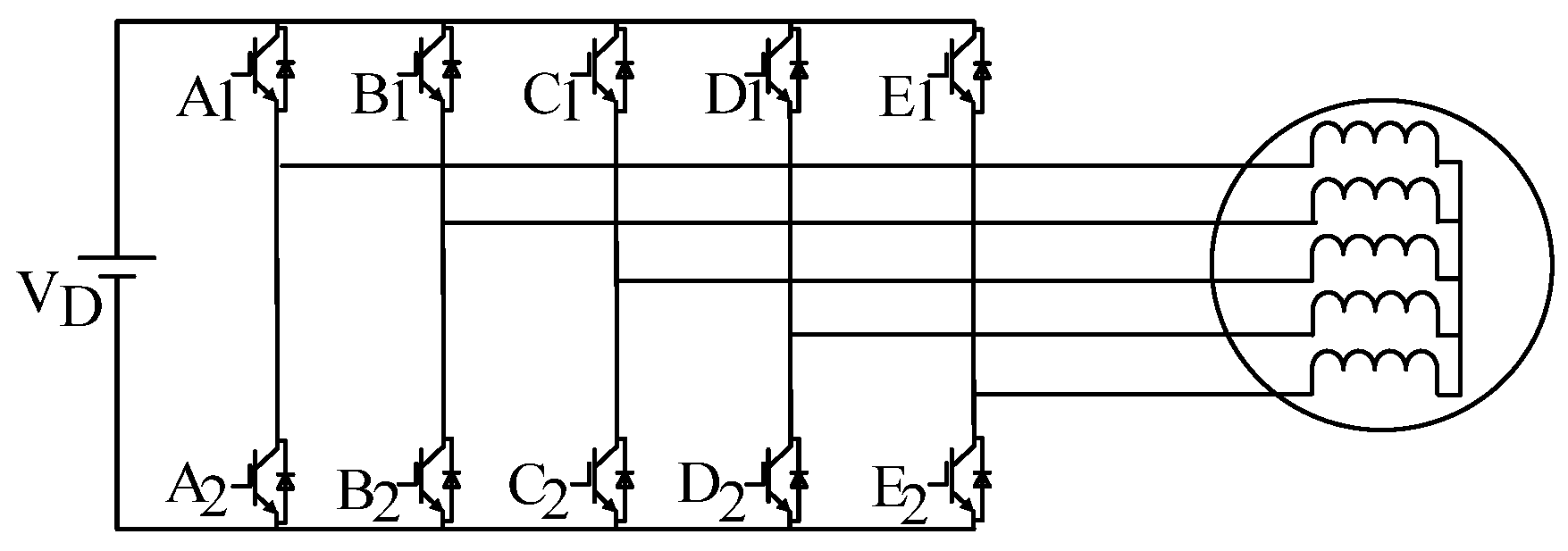
2. Topology Structure of Five-Phase Variable-Frequency Adjustable-Speed Control System

Figure 1 shows the main circuit topological structure of a five-phase variable-frequency adjustable-speed control system. The five-phase variable-frequency adjustable-speed control system consisted of a DC power source, five-phase inverter, and five-phase motor. The variable-frequency speed control of the motor could be realized by adjusting the output voltage and frequency of the five-phase inverter.
In Figure 1, the five-phase inverter adopts a full-bridge structure. A1–E2 in Figure 1 are the switching devices. The DC side bus voltage was UD, i.e., VD in Figure 1, and each bridge arm consisted of two power tubes, and the power tube turn-on and turn-off were controlled by the modulation signal. From the control theory of the AC speed control system, the voltage can be defined as space vectors a, b, c, d, and e, which were the axes of the five-phase windings of the motor. Now define the five-phase voltage vectors Uaz, Ubz, Ucz, Udz, and Uez, which were located on the axes of the five-phase winding, with the neutral point of the motor winding as the reference point, and they differed from each other by 2π/5 in spatial position, as shown in Figure 2.
Similar to the implementation of the SVPWM control algorithm for the three-phase inverter, the implementation of the SVPWM control algorithm for the five-phase inverter had the following main steps: generation of synthesis vectors, sector judgment, PWM modulation, as well as specific implementation details. Among them, regarding the judgment of the sector, it has been more complete in previous research, which was basically the same, and has been introduced more comprehensively in [25]. This paper also focuses on the generation of synthesized vectors and the over-modulation in the following content, while the specific implementation details are verified by the DSP-based FPGA experimental platform in the experimental part of the article. Finally, the experimental effect of improving the voltage transfer ratio was obtained.

3. Operating Principle and Analysis of Harmonic Characteristics of Traditional Five-Phase Space Voltage Vector Modulation

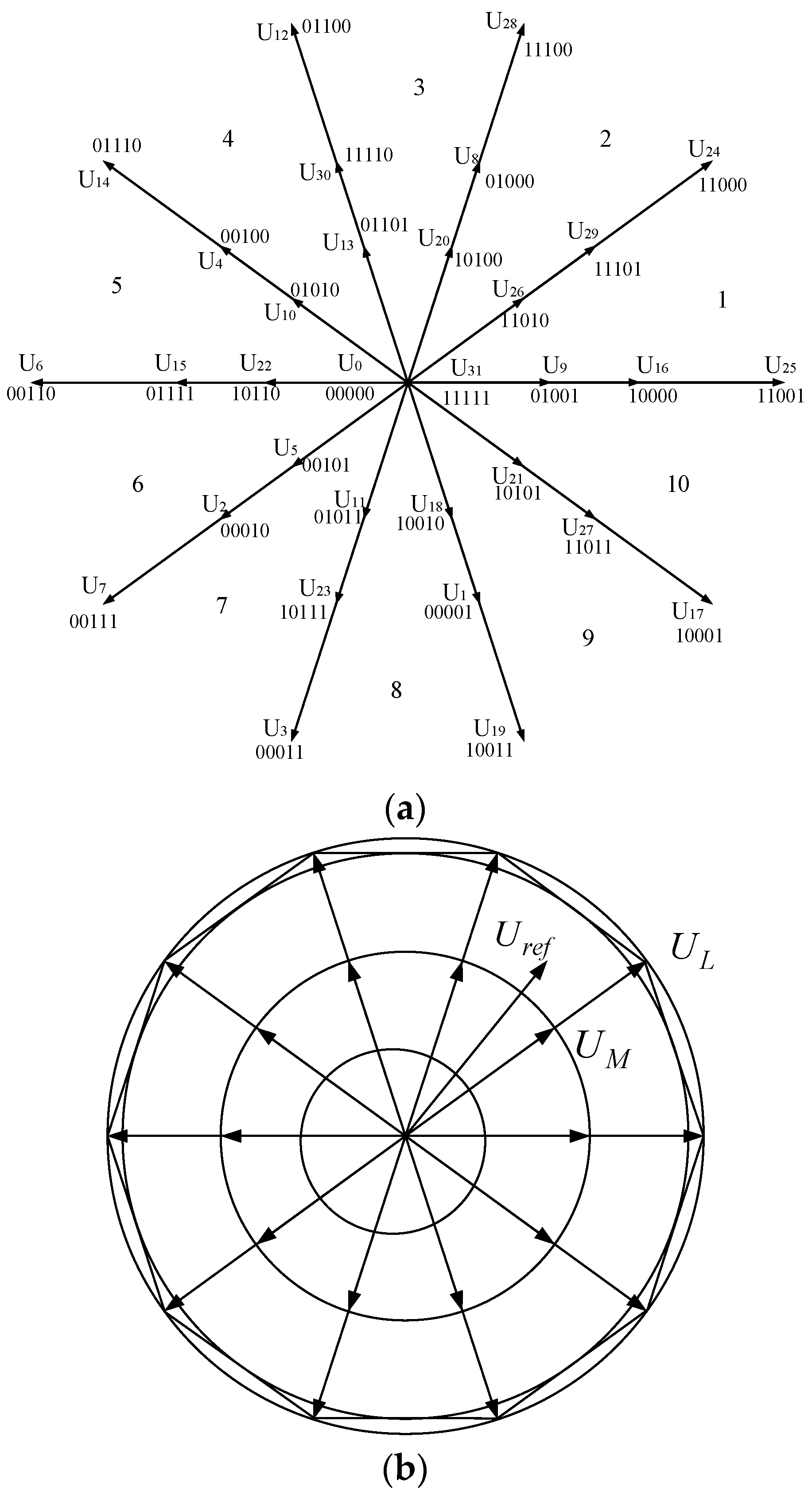
3.1. Operating Principle

Figure 3 shows the vector diagram of a five-phase inverter. When the inverter output phase voltage is referenced to the DC bus neutral, its five-phase synthesized voltage vector can be expressed by Equation (1). Thus, the five-phase synthesized vector was related to the five-phase inverter switching function. The five-phase switching function is defined as Sw = [Swa, Swb, Swc, Swd, Swe], when the upper bridge arm of phase a is turned on, Swa = l; when the lower bridge arm of phase a is turned on, Swa = 0. And at the same time, there is only one bridge arm that is on at the top and bottom, and so on. There were 32 vectors in the five-phase inverter, including 10 large vectors, 10 medium vectors, 10 small vectors, and 2 zero vectors, as shown in Table 1. The amplitude of the large vectors, the medium vectors, and the small vectors is expressed as follows:
U k = U a z + U b z + U c z + U d z + U e z   =   2 5 ( U a z + U b z e j 2 π 5 + U c z e j 4 π 5 + U d z e j 6 π 5 + U e z e j 8 π 5 )
U L = 4 5 V D 1 + 2 cos 2 π 5 U M = 4 5 V D U S = 4 5 V D 2 cos 2 π 5
Regarding the space vector modulation strategies for five-phase inverters, the literature [25] has explored the characteristics of different five-phase SVPWM algorithms when different combinations of fundamental space voltage vectors are selected and has derived the time equations for the action of each fundamental voltage vector. Among them, there are three main modulation strategies, i.e., the nearest two-vector SVPWM algorithm, maximum four-vector SVPWM algorithm, and nearest four-vector SVPWM algorithm. Since the maximum two-vector SVPWM algorithm obtained a phase voltage waveform with severe distortion and high low-harmonic content, the maximum four-vector SVPWM algorithm increased the switching losses and affected the voltage quality. In contrast, the nearest four-vector SVPWM algorithm effectively reduced the switching loss and low-level harmonic content and had good practical application results [25]. In the following, the specific principles of the recent four-vector SVPWM algorithm will be presented.
Assuming that Uref is located in sector k, the large vectors ULk and ULk+1 on both sides of sector k, the medium vectors UMk and UMk+1, and the two zero vectors U0 and U31 at the origin can be used for vector synthesis, as shown in Figure 4.
Now, the magnitude of the target voltage vector is defined as Uref, and the duration of the Uref action is still a switching cycle Ts of the inverter. Within a Ts, the duration of the large vectors ULk and ULk+1, the medium vectors UMk and UMk+1 are TLk, TLk+1, TMk, and TMk+1, respectively. The remaining time T0 = TsTMkTMk+1TLkTLk+1 is supplemented by the zero vectors U0 and U31.
Equation (3) can be obtained according to the volt–second principle.
U r e f T s = U M k T M k + U M k + 1 T M k + 1 + U L k T L k + U L k + 1 T L k + 1
Equation (3) can be obtained by αβ decomposition of Equation (4) as follows:
U r e f cos ( ω t ) T s = U M k T M k cos ( k 1 ) π 5 + U L k T L k cos ( k 1 ) π 5 + U M k + 1 T M k + 1 cos k π 5 + U L k + 1 T L k + 1 cos k π 5 U r e f sin ( ω t ) T s = U M k T M k sin ( k 1 ) π 5 + U L k T L k sin ( k 1 ) π 5 + U M k + 1 T M k + 1 sin k π 5 + U L k + 1 T L k + 1 sin k π 5
From Equation (4), it can be seen that the number of equations is less than the number of unknowns. According to linear algebra theory, there is no unique solution to the equation, so we added a constraint condition. Let the duration TLk, TLk+1 of large vectors be x times as long as the duration TMk, TMk+1 of the medium vectors, which can be substituted into a specific basic solution system.
x = T L k T M k = T L k + 1 T M k + 1
At the same time, to simplify the equation of the duration of each vector obtained by the solution, the amplitude ratio of the large vector to the medium vector is abbreviated as a = U L U M = 2 cos 2 π 5 + 1 . The duration of each vector is expressed as follows:
T M k = U r e f T s U M ( 1 + a x ) sin π 5 sin ( k π 5 ω t ) T M k + 1 = U r e f T s U M ( 1 + a x ) sin π 5 sin ( ω t ( k 1 ) π 5 ) T L k = x T M k T L k + 1 = x T M k + 1
In the linear modulation region, the VTR of the NFV-SVPWM strategy can reach 0.812.

3.2. Harmonic Characteristic

According to the principle of vector synthesis, the average output voltage in a fundamental period with the NFV-SVPWM is calculated as follows:
u A N F V = U r e f V D U M sin π 5 2 1 + x 1 + a x sin π 10 cos ω t π 10 0 < ω t π 5 2 1 + a x cos π 10 sin 3 π 10 ω t + 2 x 1 + a x sin π 10 cos 3 π 10 ω t π 5 < ω t 2 π 5 2 1 x 1 + a x cos π 10 sin ω t π 2 2 π 5 < ω t 3 π 5 2 1 + a x cos π 10 sin 7 π 10 ω t 2 x 1 + a x sin π 10 cos 7 π 10 ω t 3 π 5 < ω t 4 π 5 2 1 + x 1 + a x sin π 10 cos 9 π 10 ω t 4 π 5 < ω t π 2 1 + x 1 + a x sin π 10 cos 11 π 10 ω t π < ω t 6 π 5 2 1 + a x cos π 10 sin ω t 13 π 10 2 x 1 + a x sin π 10 cos 13 π 10 ω t 6 π 5 < ω t 7 π 5 2 1 x 1 + a x cos π 10 sin 3 π 2 ω t 7 π 5 < ω t 8 π 5 2 1 + a x cos π 10 sin ω t 17 π 10 + 2 x 1 + a x sin π 10 cos 17 π 10 ω t 8 π 5 < ω t 9 π 5 2 1 + x 1 + a x sin π 10 cos 19 π 10 ω t 9 π 5 < ω t 2 π
where x is the ratio of the large vector to the center vector in the same direction, and its expression is shown in Equation (5).
The nth harmonic amplitude an can be obtained by performing Fourier decomposition to the output voltage of the A-phase, which can be obtained as follows:
a n = f 1 n g 1 n , x + f 2 n g 2 n , x
and
f 1 n = 1 π n 1 cos n π sin n π 2 sin n 1 π 10 f 2 n = 1 π n + 1 cos n x sin n π 2 sin n + 1 π 10
g 1 n , x = 1 1 + a x 8 cos 2 n + 1 π 10 + 4 1 x cos π 10 16 1 + x sin π 10 sin 3 n π 10 cos n π 10 g 2 n , x = 1 1 + a x 8 cos 2 n 1 π 10 4 1 x cos π 10 16 1 + x sin π 10 sin 3 n π 10 cos n π 10
The calculation results showed that the value of x does not affect the fundamental amplitude a0 ≈ 0.470, and the nth harmonic amplitude is mainly determined by x. Define the total harmonic distortion THD as follows:
T H D = n = 3 a n a 1 2 × 100 %
Considering that the harmonic content is very low after 40 times, the curve of the THD varying with x was drawn by numerical simulation, as shown in Figure 5. It can be seen that with the increase of x, the THD decreases first and then increases. When x = 1.618, the third harmonic is eliminated, and the harmonic content is the lowest. After that, with the increasing of x, the THD of the output voltage increases continuously, which indicates that the long duration of the large vectors will increase the output voltage harmonics.
The main difference between the NTV-SVPWM and NFV-SVPWM is that the medium vector duration of the NTV-SVPWM is 0, and the reference voltage vector of the NTV-SVPWM is synthesized by the near-two large vectors, which shows that the ratio x of the duration of the large vector to the medium vector equals infinity, and the corresponding harmonic content improves significantly. Therefore, the operating principle and harmonic characteristics of them are not described in detail.

4. Space Voltage Vector Over-Modulation Based on Vector Weighting
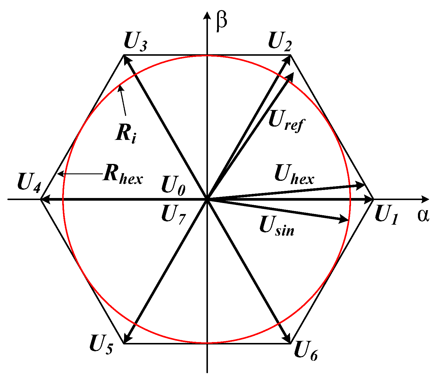
4.1. Hexagon Vector

In the conventional SVPWM method, if the reference voltage vector magnitude exceeds the range of the linear modulation region, i.e., the reference voltage vector magnitude exceeds the boundary of the positive polygon enclosed by the fundamental voltage vector, then the conventional SVPWM method cannot be used. And the part beyond the linear modulation region is also known as the nonlinear modulation region, i.e., the overmodulation region.
The VTR of the traditional three-phase space voltage vector modulation strategy is 0.866 in the linear region. To improve the VTR, the linear modulation region usually is extended to 0.909. As shown in Figure 6, the inscribed circle Ri corresponds to the VTR of 0.866, and the hexagon Rhex corresponds to the VTR of 0.909. When the VTR is between 0.866 and 0.909, the reference voltage vector is pulled back to the hexagon vector after exceeding the hexagon region. Therefore, it is necessary to calculate the holding angle ah between the hexagon vector and the reference voltage, and the relationship between the output voltage fundamental amplitude in different modulation ratios and holding angle ah can be obtained. In [24], the output voltage modulation ratio increased with a smaller holding angle. When ah = 0, the corresponding modulation ratio is 0.909.
The rotating track (blue line) and the fundamental voltage amplitude when the reference voltage vector of the five-phase inverter rotates along the hexagon corresponding to the large vector are shown in Figure 7a,b. According to the five-phase inverter space voltage vector modulation characteristics, the holding angle ah between the hexagon vector and the reference voltage vector varies from [0, π/10]. When ah = π/10, the reference vector rotates along the inscribed circle of the hexagon, and the corresponding modulation ratio can be calculated directly as cos(π/10) = 0.9512; when ah = 0, the reference vector rotates along the hexagon.
Since the reference voltage vector had period and half-wave symmetry, the output voltage fundamental amplitude of the hexagon vector can be obtained by the FFT decomposition of the A-phase voltage signal, which is shown in Figure 7b. Assuming that the holding angle is ah, the voltage fundamental amplitude is as follows in Equation (10):
U a = 4 U L π f 1 + f 2 + f 3 + f 4 + f 5 + f 6 = 4 U L π 0 a h cos ( π 10 ) cos ( π 10 a h ) cos 2 ( θ ) d θ + a h π 5 a h cos ( π 10 ) cos ( π 10 θ ) cos 2 ( θ ) d θ + π 5 a h π 5 + a h cos ( π 10 ) cos ( π 10 a h ) cos 2 ( θ ) d θ + π 5 + a h 2 π 5 a h cos ( π 10 ) cos ( 3 π 10 θ ) cos 2 ( θ ) d θ + 2 π 5 a h 2 π 5 + a h cos ( π 10 ) cos ( π 10 a h ) cos 2 ( θ ) d θ + 2 π 5 + a h π 2 cos ( π 10 ) cos ( π 2 θ ) cos 2 ( θ ) d θ
where θ is the reference voltage vector phase angle. The relationship between the modulation ratio (VTR) M and the holding angle ah can be obtained as shown Equation (11) from Equation (10).
M = 4 π 0 a h cos ( π 10 ) cos ( π 10 a h ) cos 2 ( θ ) d θ + a h π 5 a h cos ( π 10 ) cos ( π 10 θ ) cos 2 ( θ ) d θ + π 5 a h π 5 + a h cos ( π 10 ) cos ( π 10 a h ) cos 2 ( θ ) d θ + π 5 + a h 2 π 5 a h cos ( π 10 ) cos ( 3 π 10 θ ) cos 2 ( θ ) d θ + 2 π 5 a h 2 π 5 + a h cos ( π 10 ) cos ( π 10 a h ) cos 2 ( θ ) d θ + 2 π 5 + a h π 2 cos ( π 10 ) cos ( π 2 θ ) cos 2 ( θ ) d θ
When ah = 0, the reference voltage vector rotates along the hexagon. At this time, the corresponding modulation ratio M is shown as Equation (12).
M = 4 π 0 π 5 cos ( π 10 ) cos ( π 10 θ ) cos 2 ( θ ) d θ + π 5 2 π 5 cos ( π 10 ) cos ( 3 π 10 θ ) cos 2 ( θ ) d θ + 2 π 5 π 2 cos ( π 10 ) cos ( π 2 θ ) cos 2 ( θ ) d θ = 0.9661
When the reference voltage vector Uref rotates along the hexagon, the Uref is as follows:
U r e f = U L cos ( π 10 ) cos ( π 10 θ + ( k 1 ) π 5 ) e j θ
Assuming that Uref is located in sector I, since it has exceeded the maximum modulation ratio of 0.812, and can be synthesized by only the two nearest large vectors UL1, and UL2 can be used for synthesis as follows:
T s U r e f = T L 1 U L 1 + T L 2 U L 2 = T L 1 U L e j 0 + T L 1 U L e j π 5
Thus, the duration TL1 and TL2 of the two near vectors UL1 and UL2 can be obtained as follows:
T L 1 = T s U r e f cos ( π 10 ) U L sin π 5 sin k π 5 θ cos ( π 10 θ + ( k 1 ) π 5 ) T L 2 = T s U r e f cos ( π 10 ) U L sin π 5 sin k 1 π 5 θ cos ( π 10 θ + ( k 1 ) π 5 )
Other sectors can be calculated by referring to the above analysis.

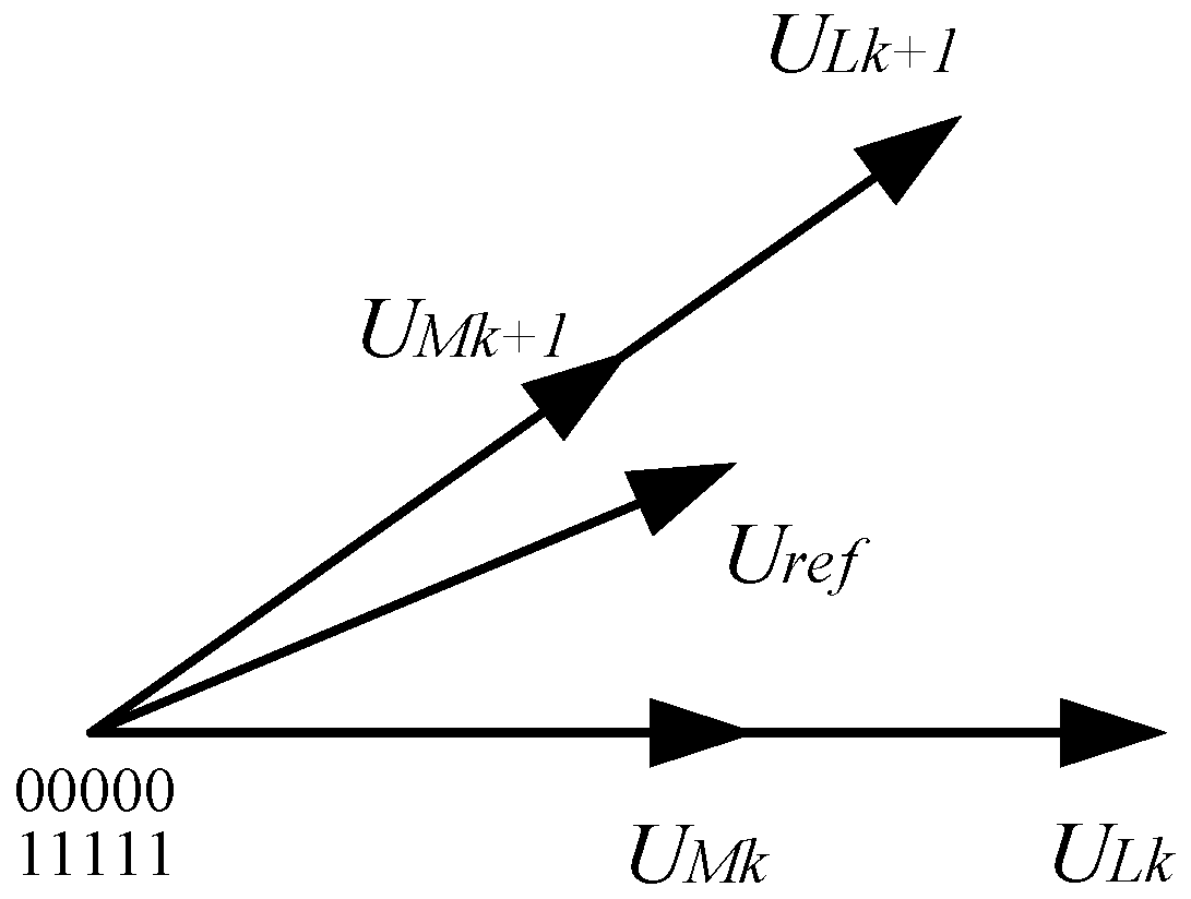
4.2. Operating Principle

To increase the VTR while decreasing the effect on the output voltage harmonics as much as possible, a five-phase space voltage vector modulation strategy based on four-vector Us4 and hexagon vector Uhex weighting is proposed. The reference voltage vector Uref is synthesized by comprehensively using four-vector Us4 and hexagon vector Uhex, where the four-vector Us4 and the hexagon vector Uhex are obtained as follows:
U s 4 = U L 0.812 sin ( ω t ) = 2 U d c 5 1 + 2 cos 2 π 5 0.812 sin ω t U h e x = U L cos π 10 cos π 10 θ + k 1 π 5 sin ω t = 2 U d c 5 1 + 2 cos 2 π 5 cos π 10 cos π 10 θ + k 1 π 5 sin ω t
Uref is synthesized by Us4 and Uhex and is shown as follows:
U r e f = s U s 4 + b U h e x
where s and b are the weighting factors of the four-vector Us4 and the decagon-vector Uhex, respectively. It can be seen from Equations (6), (12), and (17) that to decrease the output voltage error as much as possible and ensure that the output voltage fundamental amplitude outputs according to the modulation ratio M, the following equation applies:
M = 0.812 s + 0.9661 b 0 s 1 0 b 1 b + s 1
According to Section 3, to decrease the output voltage harmonic content as much as possible, the weighting factor of the four-vector Us4 is as large as possible. Therefore, the weighting factors a and b of the four-vector Us4 and hexagon vector Uhex can be obtained as follows:
s = 0.9661 M 0.9661 0.812 b = 1 s
From Equations (18) and (19), it can be seen that when M = 0.812, s = 1 and the reference voltage vector rotates between the large vector and the middle vector with NFV-SVPWM. When M = 0.9661, s = 0 and the reference voltage vector synthesized by the next nearest large vectors rotate along the hexagon. Assuming that the reference voltage is located in sector I, the space voltage four-vector Us4 and the hexagon vector Uhex are synthesized by their corresponding vectors, respectively, which are shown as follows:
U h e x T s = U L k T L k + U L k + 1 T L k + 1 U s 4 T s = U M k T M k + U M k + 1 T M k + 1 + U L k T L k + U L k + 1 T L k + 1
The duration of Us4 and Uhex with the corresponding vector is shown as Equation (21) and Equation (22), respectively.
T M k = s U r e f T s U M sin π 5 sin k π 5 θ T M k + 1 = s U r e f T s U M sin π 5 sin θ k 1 π 5 T L k = 1.618 T M k T L k + 1 = 1.618 T M k + 1
T L k = 1 s T s U r e f cos ( π 10 ) U L sin π 5 sin k π 5 θ cos ( π 10 θ + ( k 1 ) π 5 ) T L k + 1 = 1 s T s U r e f cos ( π 10 ) U L sin π 5 sin k 1 π 5 θ cos ( π 10 θ + ( k 1 ) π 5 )
In conclusion, the space voltage vector modulation ratio of the five-phase inverter can be increased from 0.812 to 0.9661 by using the proposed over-modulation strategy, and the VTR increases by 18.9%.

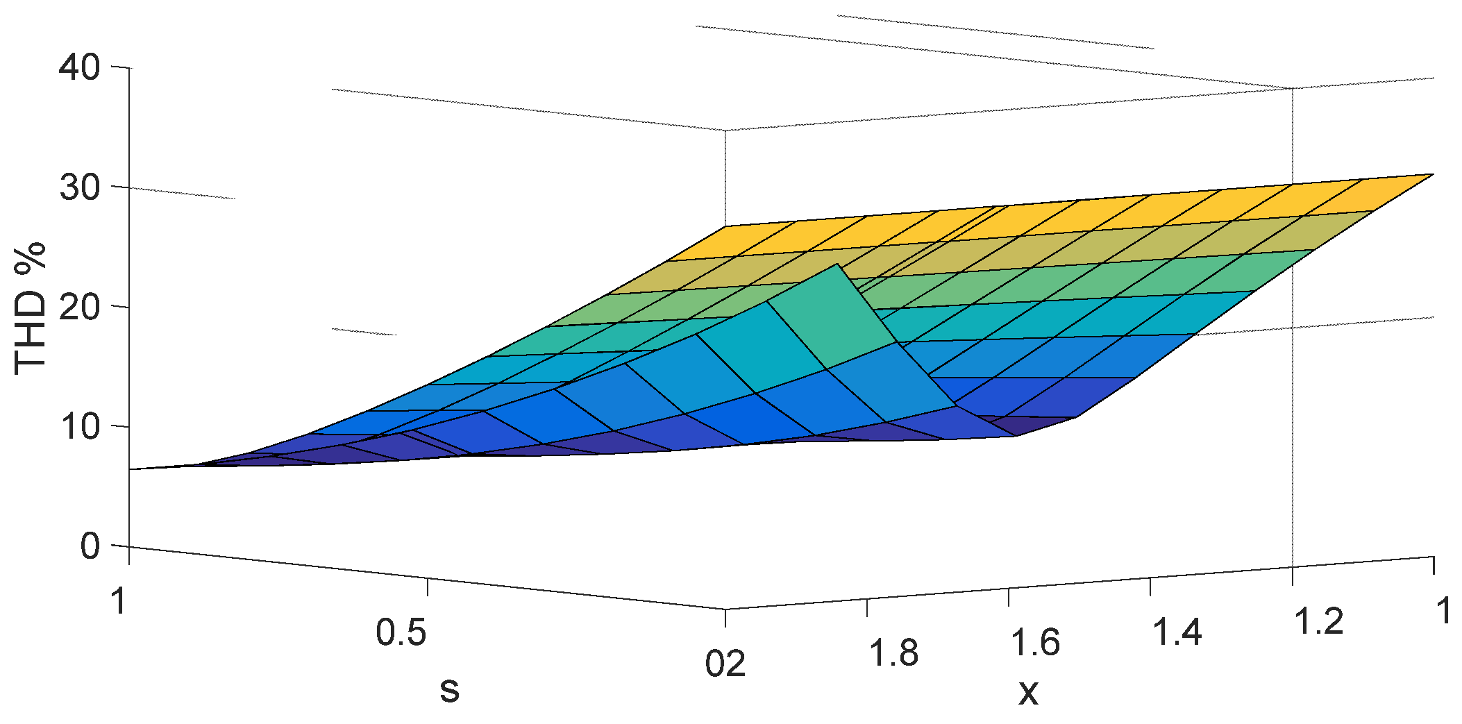
4.3. Harmonic Characteristic

According to Section 3.2, the output voltage harmonics increase with an increase in the ratio of the large vector to the medium vector duration with the traditional NFV-SVPWM. From Equation (19), it can be seen that the reference voltage vector Uref with the proposed over-modulation strategy is synthesized by adjusting the weighting factor of Us4 and Uhex. And as M increases, the weight of the hexagon vector increases continuously, in other words, the duration of the large vectors increases. Therefore, the harmonic characteristic of the output voltage vector increases varying with M increasing. The proposed over-modulation method improves the modulation ratio by sacrificing the quality of the output voltage waveform. To simplify the analysis of harmonic characteristics, the proposed over-modulation method is directly equal to the symmetrical increase in the duration of the large vector in the reference voltage vector. From Equations (8) and (19), the ratio y of the duration of the large vector to the medium vector in the proposed over-modulation strategy can be calculated as follows:
y = 1 s + s x s
Referring to the harmonic characteristic analysis method of the traditional NFV-SVPWM, the output voltage THD under different s and x is calculated by numerical simulations, as shown in Figure 8. It can be seen that when s is constant, the THD is the smallest, near 1.618 (which is the ratio of the duration of the large vector to the middle vector and is the ratio of the amplitude of the large vector to the middle vector). However, due to the increasing weight of the hexagon vector Uhex in the reference voltage vector Uref, the ratio of the duration of the large vector to the medium vector is bigger than 1.618, and the harmonic contents of the output voltage increase with x increasing, which means the output voltage waveform will continue to deteriorate. Therefore, the proposed over-modulation strategy improves the fundamental amplitude of the output voltage at the cost of deteriorating the output voltage.

5. Simulation Research and Experimental Verification

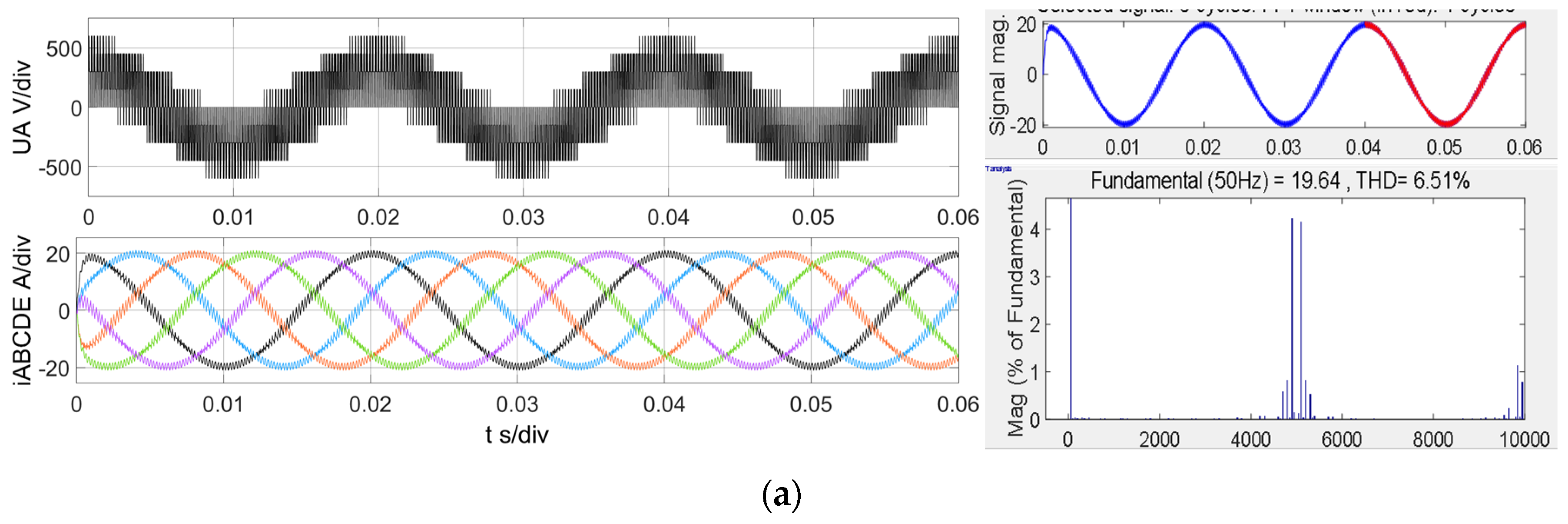
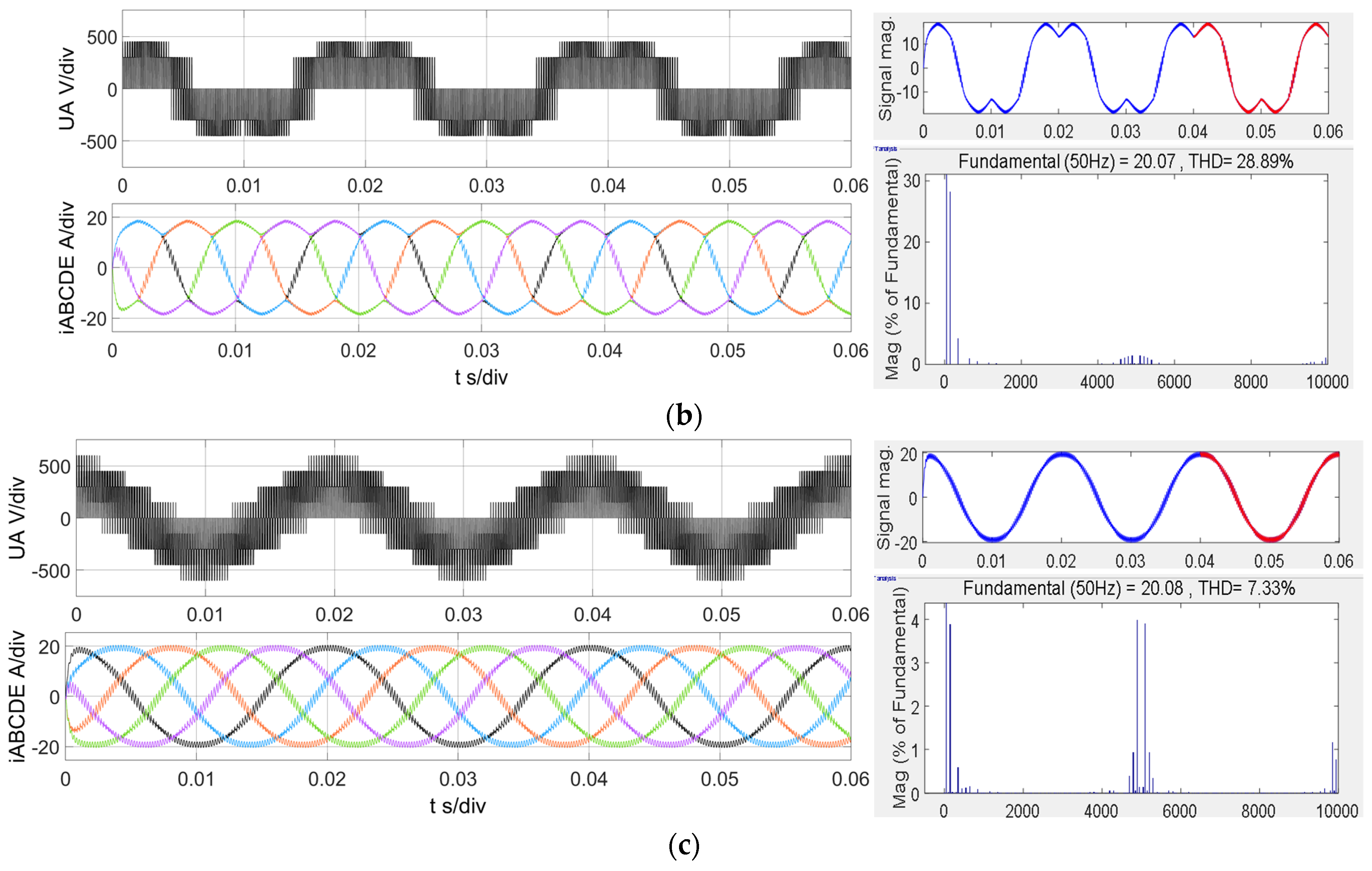
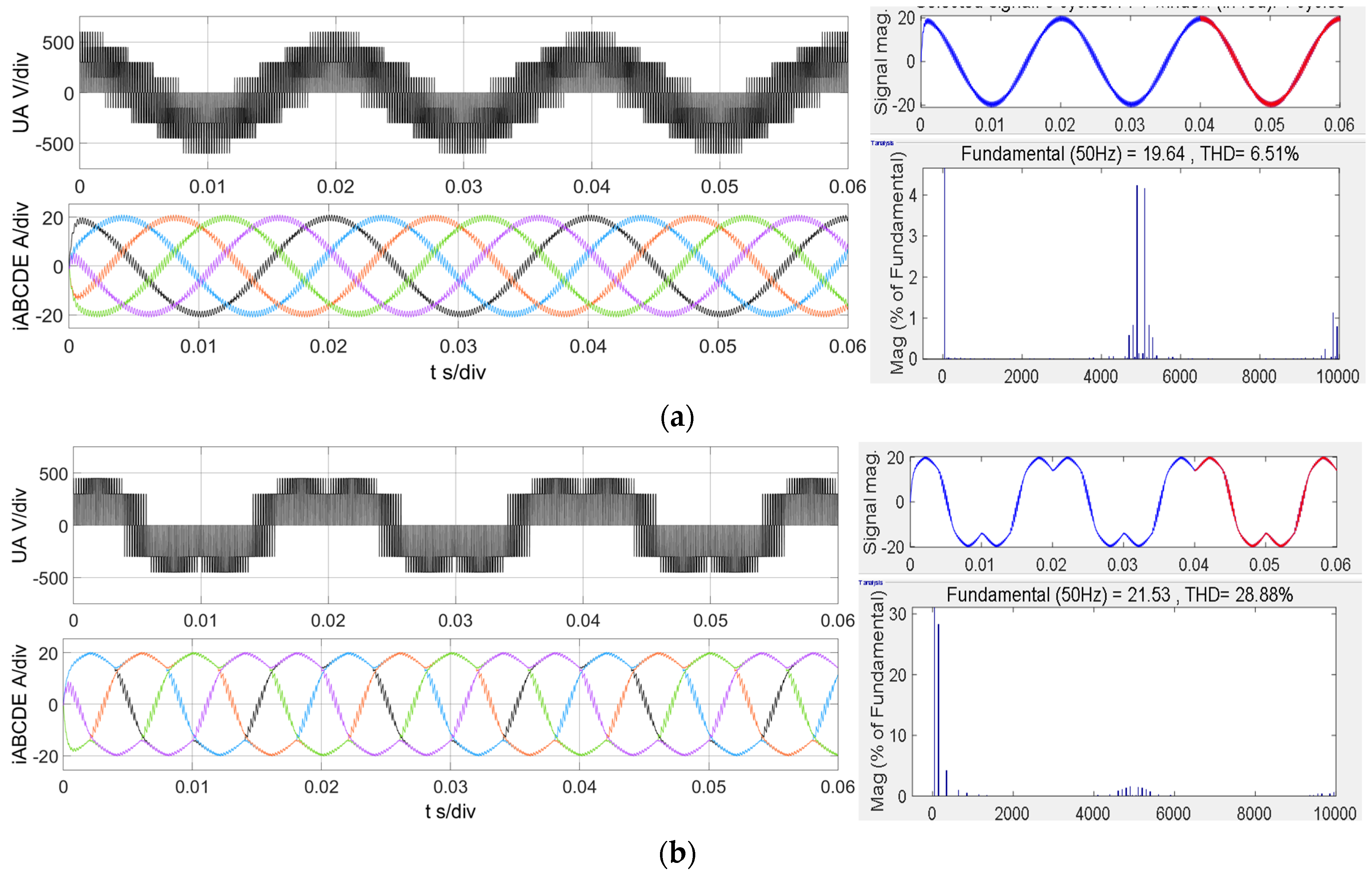
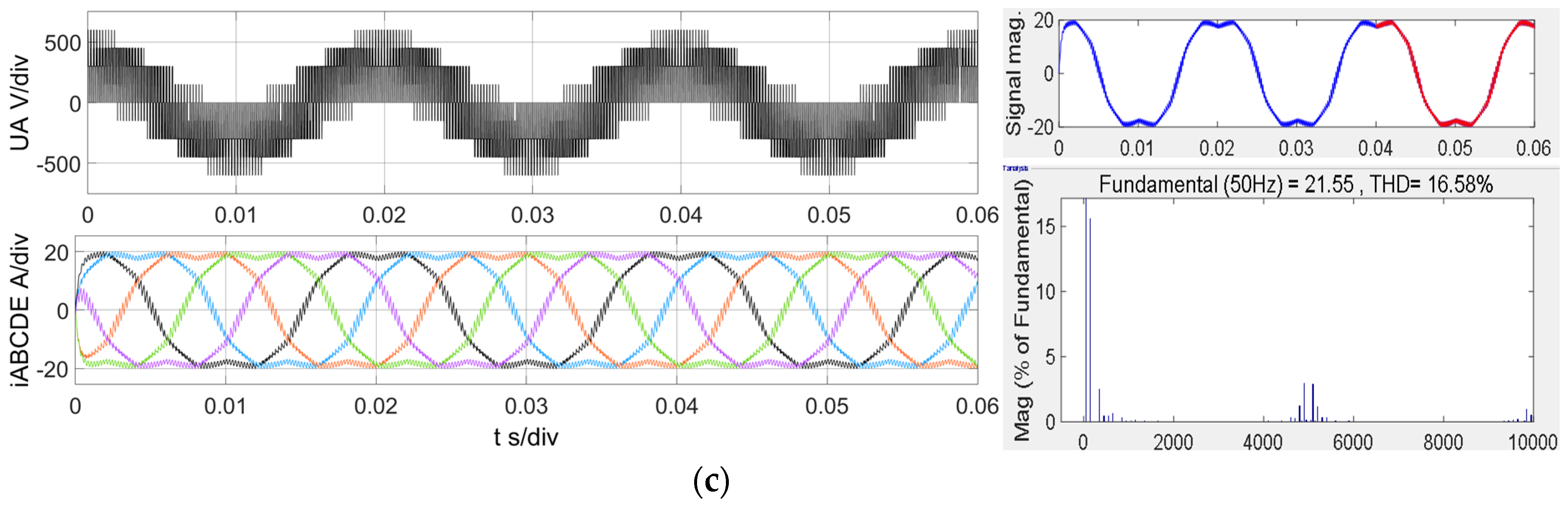
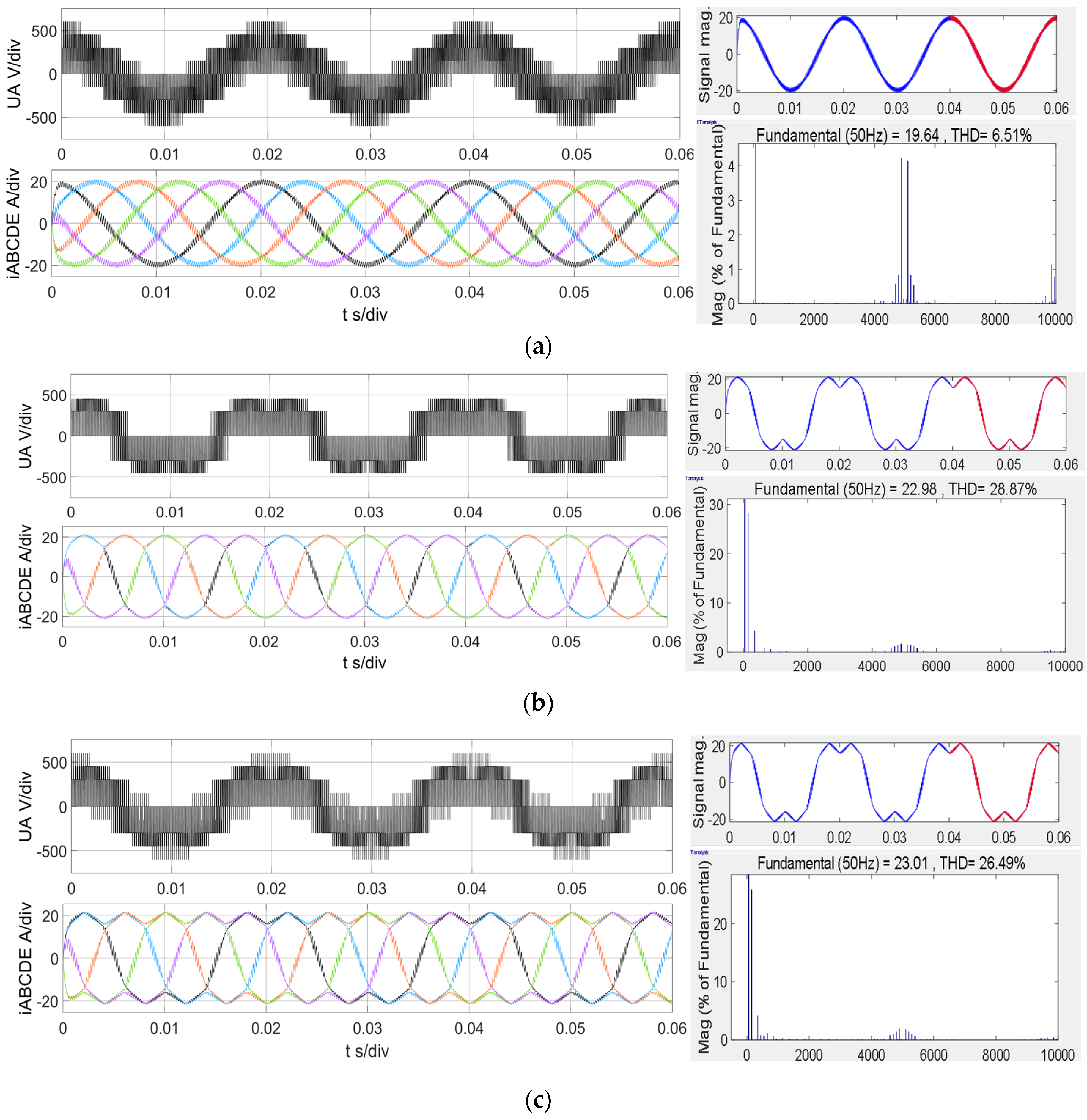
5.1. Simulation Results

In the experimental part, based on the existing experimental platform of the five-phase inverter, the simulation experiment in this part was built in Matlab software for the model of the five-phase inverter, in which the specific parameter design was also selected from the actual parameters in the actual physical platform, in which, in order to make the switching loss smaller in the actual experimental process, in the reasonable range of switching frequencies (2–20 kHz), 5 kHz was chosen as the switching frequency for this experiment. A five-phase inverter with an R-L load simulation model was built based on Matlab/Simulink software. The simulation parameters were set as shown in Table 2.
Figure 9a,b show the fundamental amplitude of the output voltage UA and the harmonic content of the output phase current iA with M changing under the traditional NFV-SVPWM, NTV-SVPWM, and proposed over-modulation strategies.
From Figure 9a, it can be seen that the output phase voltage increased with M increasing under the traditional NFV-SVPWM, NTV-SVPWM, and proposed over-modulation strategies. Both the proposed modulation strategy and NTV-SVPWM could track the desired output voltage accurately. However, when M was higher than 0.9512, the output voltage under NTV-SVPWM did not change much with M increasing. In other words, the maximum VTR under the NTV-SVPWM strategy had been reached. The output voltage under the NFV-SVPWM strategy was unchanged with M increasing in the whole modulation region. The main reason was that when M was 0.812, the duration of the synthesis vectors ULk, ULk+1, UMk, and UMk+1 reached the maximum effective value, which meant the zero vector duration was 0. Even if M increased, the synthesis vector duration was unchanged, so the output phase voltage did not change with M increasing under the NFV-SVPWM strategy.
From Figure 9b, it can be seen that the output phase current harmonics almost did not change with M increasing under the NFV-SVPWM strategy. Although the output voltage increased with M increasing under the NTV-SVPWM strategy, the harmonic content did not change much. The main reason was that the duration of the synthetic vectors increased proportionally, so the waveform of the synthesized reference voltage vector did not change. The rotating track of the synthetic vectors was similar, varying with M. The main difference was that the rotating track was proportionally expanded outward with a different M. The proposed over-modulation strategy changed the duration of the large vectors and the medium vectors, and the harmonic content increased with the increase in the ratio of the duration of the large vectors to the medium vectors. The simulation results were consistent with the theoretical analysis, indicating that the proposed over-modulation method can effectively improve the fundamental amplitude of the output voltage, but it will increase the output current harmonics.
Figure 10, Figure 11 and Figure 12 show the output phase voltage, phase current, and FFT spectrum with M = 0.83, 0.89, and 0.95 under the three modulation strategies of the traditional NFV-SVPWM, NTV-SVPWM, and proposed over-modulation strategies, respectively. From Figure 10, Figure 11 and Figure 12, compared with the traditional NFV-SVPWM, it can be seen that the proposed over-modulation method had a higher output voltage fundamental amplitude, but the output current harmonic content was higher; compared with the NFV-SVPWM method, the output current of the proposed over-modulation method had a better sine degree and could obtain lower output current harmonics. It can be seen that the proposed over-modulation method can effectively improve the output voltage fundamental amplitude and had better output performance.
From the above, it can be seen that in the case of the different modulation ratios M, different situations occurred, but as the modulation ratio increased, the fundamental amplitude of the output phase voltage increased, and the improved strategy produced better results than the traditional two strategies. And from the above, this can be obtained from the comparison of the harmonic content of the phase currents under different modulation ratios, as shown in the Table 3 below, and the final results presented are also in agreement with Figure 9.

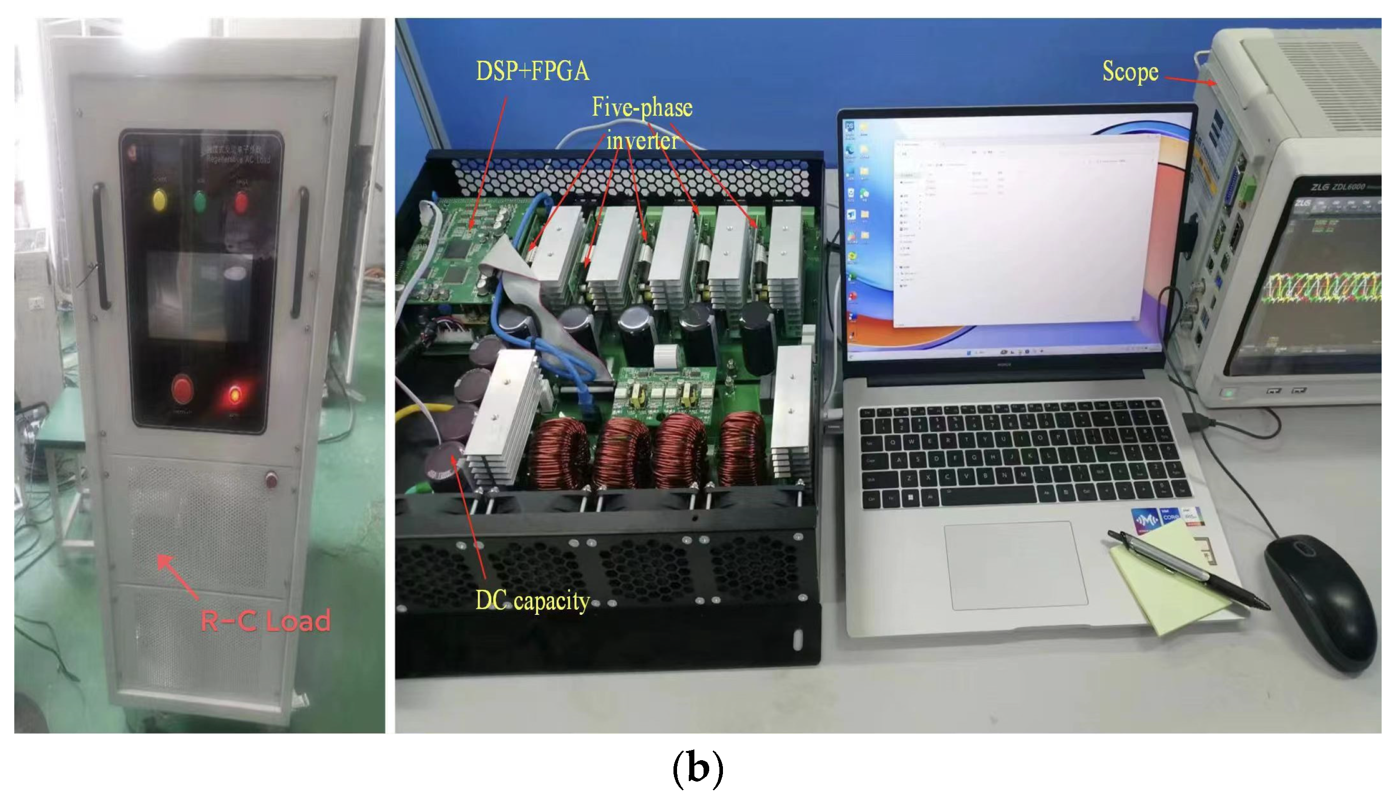
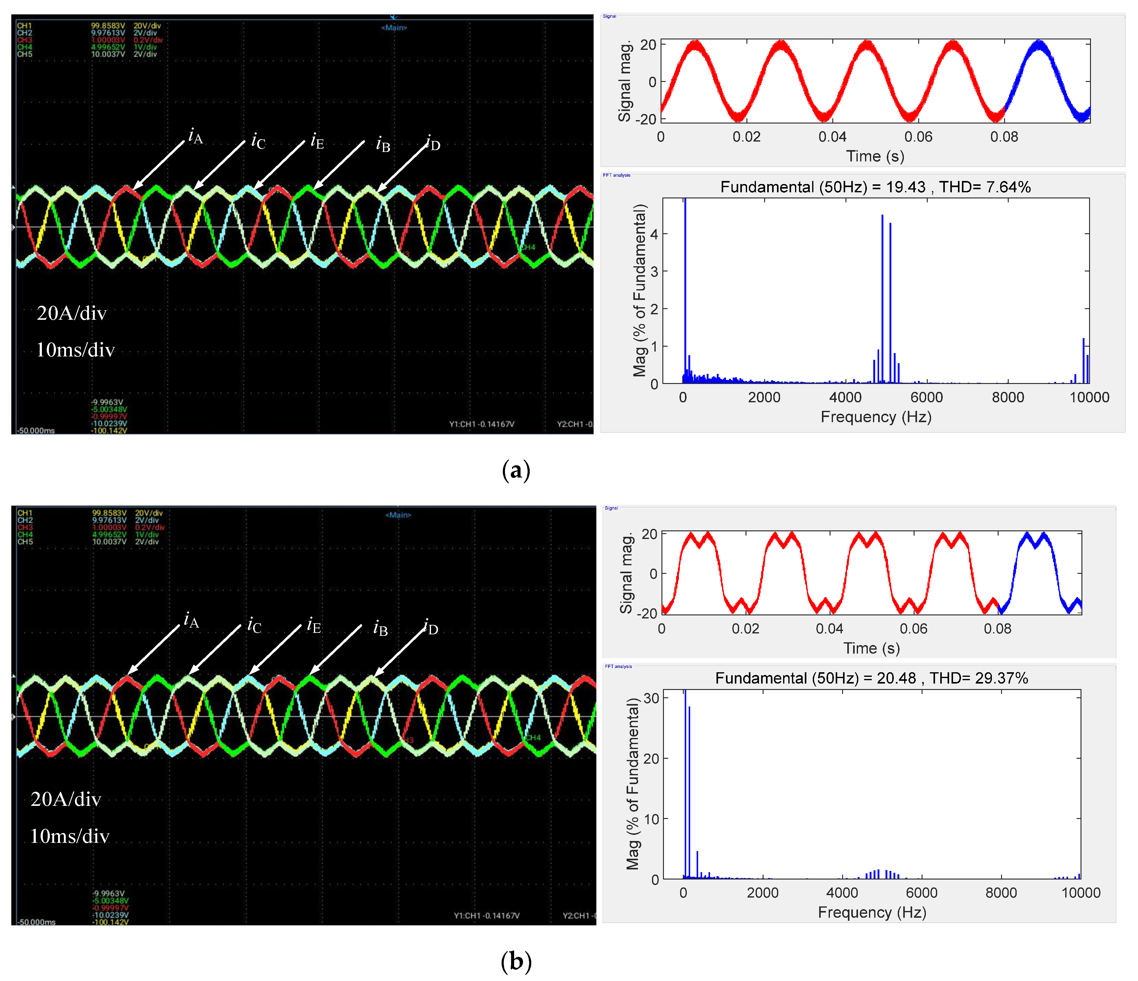
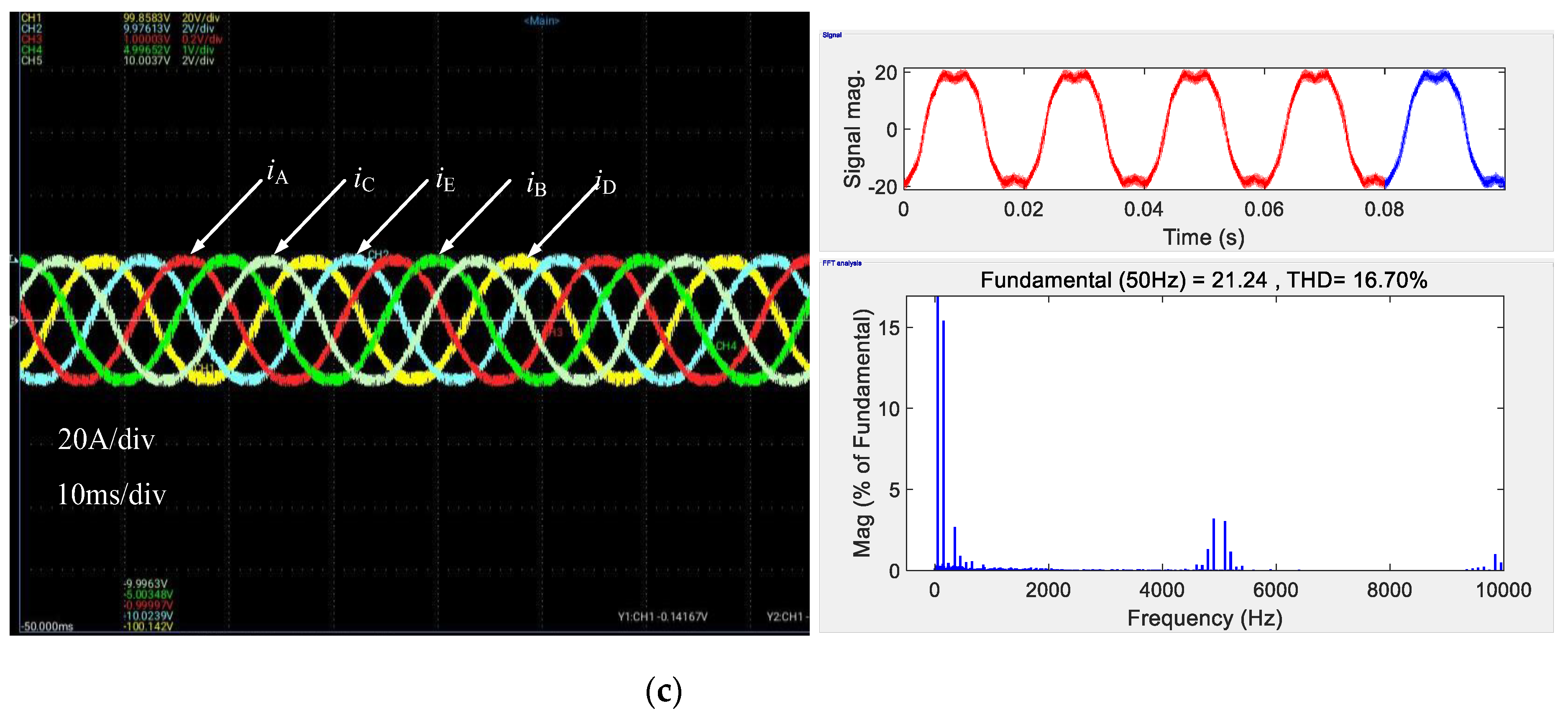
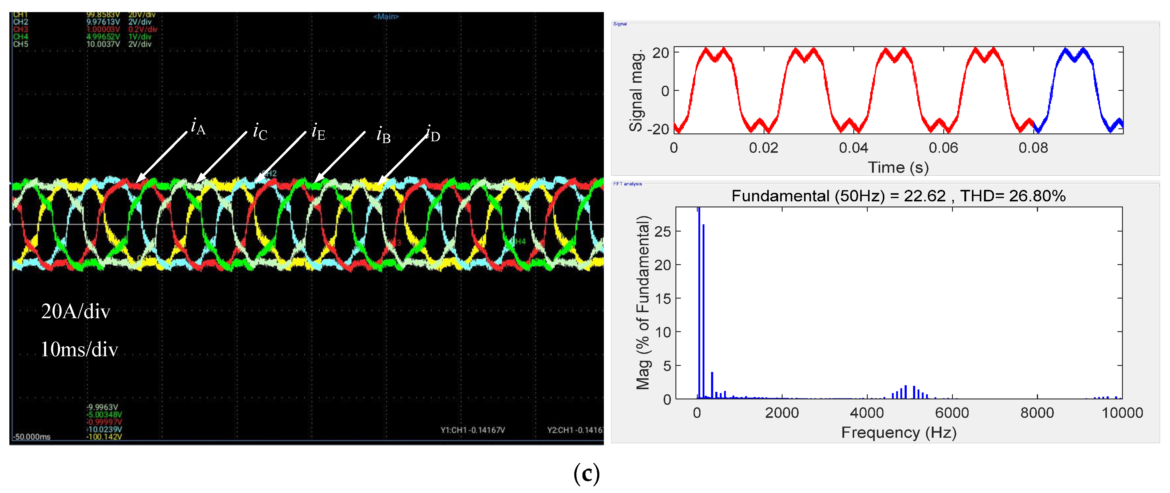
5.2. Experimental Verification

In order to verify the accuracy of the theoretical analysis and the feasibility of the proposed strategy, we set up a semi-physical and physical experimental platform composed of DSP and FPGA, as shown in Figure 13. The experimental results were basically consistent with the simulation parameters, and the experimental parameters were consistent with the simulation parameters.
Figure 14, Figure 15 and Figure 16 show the output current and THD with M = 0.83, 0.89, and 0.95 under the traditional NFV-SVPWM, NTV-SVPWM, and proposed over-modulation strategies, respectively. Compared with Figure 14c, Figure 15c and Figure 16c, it can be seen that both the output current and its THD with the proposed modulation strategy increased with M increasing. Compared with Figure 13a, Figure 14a and Figure 15a, it can be seen that with M increasing, the output current characteristics of the traditional NFV-SVPWM remained unchanged, which indicated that when M was higher than 0.812, the output voltage of the traditional NFV-SVPWM did not change. Compared with the NFV-SVPWM, the proposed over-modulation strategy can effectively improve the VTR but will increase the output harmonics. Compared with the NTV-SVPWM, the proposed over-modulation strategy can effectively improve the VTR, and the harmonic content is lower. The experimental results were consistent with the theoretical analysis and simulation results, which verified that the theoretical analysis was correct, and the proposed over-modulation strategy is feasible.

6. Conclusions

Aiming at the problems of a low VTR of the traditional NFV-SVPWM and high-output harmonic content of the traditional NTV-SVPWM, an over-modulation strategy based on multi-vector weight is proposed by analyzing the operation principle and harmonic characteristics of the traditional NFV-SVPWM. That is to say, the reference voltage vector was synthesized by adjusting the weight of the hexagon vector and the nearest four-vector. The simulation results showed that the modulation method could effectively improve the output voltage base amplitude, and the method to improve the carrying capacity of the five-phase frequency-conversion speed-regulation system had certain significance, but the disadvantage was that the output current harmonic will increase with an increase in the modulation ratio. We finally also verified that the modulation method was correct and feasible. Through the experimental verification of the method proposed in this paper, it is not difficult to see that the over-modulation method can indeed effectively improve the fundamental amplitude of the voltage. However, in the process of the experiment, the voltage ripple increased, and because the current harmonic content increased, the situation was not able to be effectively improved. In subsequent research, the relevant scholars can solve this problem by changing some of the structure of the circuit, such as increasing the value of the inductance and other methods.

Author Contributions

Conceptualization, M.J.; methodology, Y.X.; software, Y.M.; validation, M.J., Y.X., and Y.M.; formal analysis, M.J.; investigation, Y.M.; resources, Y.X.; data curation, M.J.; writing—original draft preparation, Y.X.; writing—review and editing, Y.X.; visualization, Y.X.; supervision, Y.M.; project administration, Y.X.; funding acquisition, Y.X. All authors have read and agreed to the published version of the manuscript.

Funding

This research was funded by the National Natural Science Foundation of China (Grant No. 51877212).

Data Availability Statement

Data are contained within the article.

Conflicts of Interest

The authors declare no conflict of interest.

References

  1. Ma, W.; Wang, D.; Cheng, S.; Chen, J. Common basic scientific problems and development of leading-edge technology of high performance motor system. Proc. CSEE 2016, 36, 2025–2035. (In Chinese) [Google Scholar]
  2. Levi, E. Advances in converter control and innovative exploitation of additional degrees of freedom for multiphase machines. IEEE Trans. Ind. Electron. 2016, 63, 433–448. [Google Scholar] [CrossRef]
  3. Duran, M.J.; Barrero, F. Recent advances in the design, modeling, and control of multiphase machines—Part II. IEEE Trans. Ind. Electron. 2016, 63, 459–468. [Google Scholar] [CrossRef]
  4. Tao, T.; Zhao, W.X.; Cheng, M.; Wang, Z. Review on fault-tolerant control of multi-phase machines and their key technologies. Proc. CSEE 2019, 39, 316–326. (In Chinese) [Google Scholar]
  5. Tian, B.; Mirzaeva, G.; An, Q.T.; Sun, L.; Semenov, D. Fault-tolerant control of a five-phase permanent magnet synchronous motor for industry applications. IEEE Trans. Ind. Appl. 2018, 54, 3943–3952. [Google Scholar] [CrossRef]
  6. Liu, Z.; Li, Y.; Zheng, Z. Control and drive techniques for multiphase machines: A review. Trans. China Electrotech. Soc. 2017, 32, 17–29. [Google Scholar]
  7. Liu, Z.; Zheng, Z.; Li, Y. Enhancing fault-tolerant ability of a nine-phase induction motor drive system using fuzzy logic current controllers. IEEE Trans. Energy Convers. 2017, 32, 759–769. [Google Scholar] [CrossRef]
  8. Zhu, P.; Zhang, X.; Qiao, M.; Zhang, C.; Cai, W. Five-phase induction motor SVM-DTC strategies with third harmonic voltage injection. Electr. Mach. Control 2010, 14, 13–18. [Google Scholar]
  9. Bermúdez, M.; Gonzalez, P.I.; Barrero, F.; Guzman, H.; Duran, M.J.; Kestelyn, X. An experimental assessment of open-phase fault-tolerant virtual-vector-based direct torque control in five-phase induction motor drives. IEEE Trans. Power Electron. 2018, 33, 2774–2784. [Google Scholar] [CrossRef]
  10. Zhang, W.; Chen, B.; Zhang, P. Techniques to restrain harmonics of dual three-phase permanent magnet synchronous motor. Electr. Mach. Control 2015, 19, 23–28. [Google Scholar]
  11. Zhu, P.; Zhang, X.; Qiao, M.; Cai, W.; Liang, J. Tolerant control strategy for five-phase concentrated full-pitch windings induction motor under open phases fault. Proc. CSEE 2011, 31, 131–137. [Google Scholar]
  12. Yu, F.; Zhang, X.; Li, H.; Song, Q. Space vector PWM control of five-phase inverter. Proc. CSEE 2005, 25, 40–46. [Google Scholar]
  13. Yu, F.; Zhang, X.; Li, H.; Xiang, D. Discontinuous space vector PWM control of five-phase inverter. Trans. China Electro Tech. Soc. 2006, 21, 26–30. [Google Scholar]
  14. Tang, J.; Wang, T.; Cuii, S.M. Implementation method of SVPWM for five-phase inverters. Trans. China Electro Tech. Soc. 2013, 28, 64–72. [Google Scholar]
  15. Meng, F.; Zhang, C. Research on space vector control strategy based on five-phase five-level H-bridge inverter. Appl. Sci. Technol. 2017, 44, 43–47. [Google Scholar]
  16. Xue, C.; Song, W.; Wu, X.; Feng, X. A constant switching frequency finite-control-set predictive current control scheme of a five-phase inverter with duty-ratio optimization. IEEE Trans. Power Electron. 2018, 33, 3583–3594. [Google Scholar] [CrossRef]
  17. Iqbal, A.; Abu-Rub, H.; Cortes, P.; Rodriguez, J. Finite control set model predictive current control of a five-phase voltage source inverter. In Proceedings of the 2010 IEEE International Conference on Industrial Technology, Via del Mar, Chile, 14–17 March 2010; pp. 1787–1792. [Google Scholar]
  18. Cortés, P.; Vattuone, L.; Rodriguez, J.; Duran, M. A method of predictive current control with reduced number of calculations for five-phase voltage source inverters. In Proceedings of the 2009 35th Annual Conference of IEEE Industrial Electronics, Porto, Portugal, 3–5 November 2009; pp. 53–58. [Google Scholar]
  19. Zhou, C.; Yang, G.; Su, J. PWM strategy with minimum harmonic distortion for dual three-phase permanent-magnet synchronous motor drives operating in the overmodulation region. IEEE Trans. Power Electron. 2016, 31, 1367–1380. [Google Scholar] [CrossRef]
  20. Komrska, T.; Glasberger, T.; Peroutka, Z. Universal PWM modulator for multiphase drives with a minimum infinity-norm approach. IEEE Trans. Ind. Electron. 2016, 63, 5979–5987. [Google Scholar] [CrossRef]
  21. Priestley, M.; Fletcher, J.E. Space-vector PWM technique for five phase open-end winding PMSM drive operating in the overmodulation region. IEEE Trans. Ind. Electron. 2018, 65, 6816–6827. [Google Scholar] [CrossRef]
  22. Vancini, L.; Mengoni, M.; Rizzoli, G.; Sala, G.; Zarri, L.; Tani, A. Carrier-Based PWM Overmodulation Strategies for Five-Phase Inverters. IEEE Trans. Power Electron. 2021, 36, 6988–6999. [Google Scholar] [CrossRef]
  23. Liu, H.; Yi, X.; Wang, D.; Zheng, X.; Meng, F. An Efficiency-optimized Control Strategy in the Full Torque Operation Range for Five-phase Induction Motor under Open-circuited Fault Conditions. Proc. CSEE 2020, 40, 1642–1652. [Google Scholar]
  24. Peng, Z.; Zheng, Z.; Liu, Z. A novel sensorless fault-tolerant control of five-phase induction machine using virtual winding and full-order observer. Trans. China Electrotech. Soc. 2018, 33, 4949–4961. [Google Scholar]
  25. Pu, T. Research on Novel Space Vector Pulse Width Modulation Technique for Five-Phase Inverter. Master’s Thesis, Nanjing University of Aeronautics and Astronautics, Nanjing, China, 2020. [Google Scholar]
Figure 1. Main circuit topological structure of five-phase variable-frequency speed control system.
Electronics 13 01907 g001
Figure 2. Schematic diagram of spatial distribution of five-phase voltage vector.
Electronics 13 01907 g002
Figure 3. Space voltage vector and synthesis vector diagram. (a) Voltage vector distribution diagram. (b) Vector synthesis schematic diagram.
Electronics 13 01907 g003
Figure 4. Vector synthesis of NFV-SVPWM in sector k.
Electronics 13 01907 g004
Figure 5. THD of NFV-SVPWM varies with x.
Electronics 13 01907 g005
Figure 6. Three-phase inverter space voltage vector modulation.
Electronics 13 01907 g006
Figure 7. Reference voltage vector track and fundamental voltage amplitude projection. (a) Space voltage vector. (b) Fundamental voltage projection.
Electronics 13 01907 g007
Figure 8. Output voltage harmonic content under different s and x.
Electronics 13 01907 g008
Figure 9. The simulation results of the output phase voltage fundamental amplitude and the phase current harmonic contents varying with M under three modulation strategies. (a) The amplitude of output phase voltage. (b) The THD of the output phase current.
Electronics 13 01907 g009
Figure 10. The output phase voltage, phase current, and FFT spectrum under three modulation strategies with M = 0.83. (a) The traditional NFV-SVPWM. (b) The traditional NTV-SVPWM. (c) The proposed strategy.
Electronics 13 01907 g010aElectronics 13 01907 g010b
Figure 11. The output phase voltage, phase current, and FFT spectrum under three modulation strategies with M = 0.89. (a) The traditional NFV-SVPWM. (b) The traditional NTV-SVPWM. (c) The proposed strategy.
Electronics 13 01907 g011aElectronics 13 01907 g011b
Figure 12. The output phase voltage, phase current, and FFT spectrum under three modulation strategies with M = 0.95. (a) The traditional NFV-SVPWM. (b) The traditional NTV-SVPWM. (c) The proposed strategy.
Electronics 13 01907 g012
Figure 13. Semi and real physical experimental platforms. (a) Semi-physical experimental platform. (b) Real experimental platform.
Electronics 13 01907 g013aElectronics 13 01907 g013b
Figure 14. Experimental results of output current and its THD with M = 0.83. (a) The traditional NFV-SVPWM. (b) The traditional NTV-SVPWM. (c) The proposed strategy.
Electronics 13 01907 g014aElectronics 13 01907 g014b
Figure 15. Experimental results of output current and its THD with M = 0.89. (a) The traditional NFV-SVPWM. (b) The traditional NTV-SVPWM. (c) The proposed strategy.
Electronics 13 01907 g015aElectronics 13 01907 g015b
Figure 16. Experimental results of output current and its THD with M = 0.95. (a) The traditional NFV-SVPWM. (b) The traditional NTV-SVPWM. (c) The proposed strategy.
Electronics 13 01907 g016aElectronics 13 01907 g016b
Table 1. Space voltage vector amplitude.
Voltage VectorAmplitude
Large VectorU3, U6, U7, U12, U14, U17, U19, U24, U25, U28 U L = 4 5 V D 1 + 2 cos 2 π 5
Medium Vector U1, U2, U4, U8, U15, U16, U23, U27, U29, U30 U M = 4 5 V D
Small VectorU5, U9, U10, U11, U13, U18, U20, U21, U22, U26 U S = 4 5 V D 2 cos 2 π 5
Table 2. Simulation parameters.
ParameterValue
DC Voltage/DC Capacitance750 V/4700 uF
Output Voltage/Frequency380 V/50 Hz
R-L LoadR = 20 Ω, L = 5 mH
Switching Frequency fs5 kHz
Table 3. Comparison of phase voltage harmonic content with different modulation ratios (M).
Modulation Ratio (M)NFV-SVPWM MethodProposed MethodNTV-SVPWM Method
0.836.51%7.33%28.89%
0.896.51%16.58%28.88%
0.956.51%26.49%28.87%
Disclaimer/Publisher’s Note: The statements, opinions and data contained in all publications are solely those of the individual author(s) and contributor(s) and not of MDPI and/or the editor(s). MDPI and/or the editor(s) disclaim responsibility for any injury to people or property resulting from any ideas, methods, instructions or products referred to in the content.

