Abstract
The global population is rapidly increasing, and the urban population is on an even faster trend; therefore, the population density is expected to rise. As the number of people in cities grows, the demand for high-rise buildings is anticipated to increase to address the problem of limited land resources. Therefore, efficient energy management using distributed resources has become increasingly important. Elevators are a vital vertical means of transportation in high-rise buildings, and reducing the weight of their components can lead to favorable conditions for energy utilization and increased speed. Therefore, this study presents an elevator system that supplies power inside an elevator car by eliminating the traveling cable and applying a small-capacity energy storage system (ESS). Additionally, we propose a charging algorithm suitable for the proposed system. Generally, batteries have sensitive electrical properties among the distributed energy resources (DERs). Therefore, controlling the stable maintenance of the transient state of the charging current—even when the DC power is unstable or the load changes rapidly in a system requiring fast charging—is crucial. Owing to the nature of the elevator system to be applied, discontinuous charging is frequent, and the active and efficient management of the battery state of charge (SOC) may be challenging. In addition, since it is necessary to be able to charge as much as possible during a short discontinuous charging time, a current control algorithm with a stable and high-speed response is required. The proposed transient high-speed tracking controller (THSTC) is a method for tracking the time of applying an inductor’s excitation voltage without pulse–width modulation (PWM) switching, which is less sensitive to the controller gain values and has fast responsiveness as well as stable transient response characteristics. The proposed method has good dynamic characteristics with a simple control structure without a complex design, which is useful for systems with repeated discontinuous charging. We validate the performance and effectiveness of the proposed controller through simulations and experiments.
1. Introduction
The population densities in large cities are increasing alongside global population growth. Consequently, high-rise buildings are increasingly utilized to address the issue of limited land resources [1,2,3]. Accordingly, the demand for high-speed elevators is increasing and related studies are underway [4,5]. The main components of the elevator system include the rope system, motor, car, counterweight, and traveling cable. The speed of the elevator is influenced by the performance and safety of the major components as well as various factors, such as the internal environment of the building, manufacturer, purpose of use, and regulation. Suppose that several conditions, including the main components of the elevator, are the same. In that case, implementing a high-rise, high-speed elevator would be advantageous, provided that the load of the elevator connected to the rope can be reduced [6,7].
A counterweight is used to compensate for the equivalent weight of the elevator car connected to the rope, and a traveling cable is used to supply power inside the car. The weight applied to the rope by the traveling cable varies depending on the position of the car—the higher the height of the building, the greater the weight variation. Therefore, it is difficult to compensate for the optimal equivalent weight using the count weight [8,9]. The removal of the traveling cable can reduce the load applied to the rope, thereby increasing the speed and energy efficiency of the elevator [10,11,12,13,14,15]. Accordingly, it presents an elevator system that supplies power by removing the traveling cable and installing a small ESS on top of a car. Figure 1a shows the configuration of a typical elevator system that receives power through a traveling cable. Figure 1b shows the elevator system configuration when applying the power supply method without a traveling cable as proposed in this study. The charging of the small-capacity ESS is conducted through a bus bar configured along the inside of the liftway, similar to the pantograph device applied on trains [16,17,18,19,20].
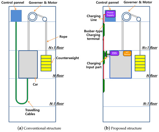
Figure 1.
Configuration of the elevator system with removed traveling cable.
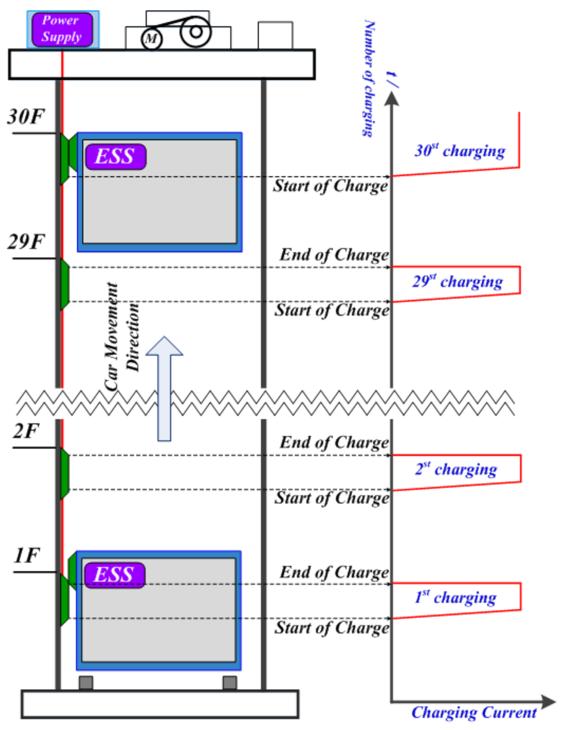
However, when a bus bar is configured on all floors, the disadvantage is that the installation cost is higher than that of a general traveling cable. To solve this problem, we can consider installing the bus bar only on odd or even floors, and in some sections where the elevator car stops. In this study, we interpret the system assuming that the bus bar is configured on all floors and only in specific sections where the car stops, as shown in Figure 1b. In the assumed system, the ESS is charged while the car moves to the target layer; accordingly, as shown in Figure 2, charging starts and ends repeatedly by discontinuous power supply.
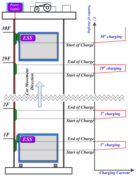
Figure 2.
Charging pattern of ESS when moving the car from the 1st to the 30th floor.
Accordingly, the power converter for charging the ESS configured in an elevator car requires the following functions: First, it should have a current-control function with excellent dynamic characteristics that can respond to a discontinuous power supply, as illustrated Figure 2. Owing to the characteristics of elevator cars, the limited ESS capacity, and significantly irregular operation patterns, a high-speed current controller with excellent dynamic characteristics is required to ensure a stable SOC. Second, significant chattering may occur in the input voltage during the transient state of charging, due to the line impedance and contact-type charging terminals. This is a result of the long lines from the power supply to the charging terminal. Therefore, stable transient response characteristics that can compensate for such instability in DC power are required.
A typical proportional–integral (PI) controller designs control variables based on a linear mathematical model. Although the modeled conditions provide satisfactory performance, the performance cannot be guaranteed in terms of parameter variation, nonlinearity, load disturbance, etc. [21,22,23]. Fast response can be improved by applying appropriate PI gain values and anti-wind-up, but overshoot will occur from the time the inductor current reaches near the target value. There is a trade-off between reducing the rising time and minimizing overshoot. To compensate for these shortcomings, many strong, fast, and stable controllers have been proposed for external disturbances. Advanced PI controllers, state-feedback control, and sliding mode control (SMC) exist that vary the gain, considering various operating conditions or load disturbances. However, the disadvantage is that a complex design is required to apply these control techniques. The controller design is a purely mathematical expression derived from differential equations. However, a power converter is an actual circuit that consists of inductors, capacitors, switches, diodes, etc. Therefore, it is necessary to confirm whether the controller obtained from the mathematical model shows the same response characteristics during actual circuit operations. The more complex the design, the more time it takes to confirm. The more complex the control algorithm, the higher the computation amount. In general, control codes are executed in synchronization with the switching frequency or sampling frequency, so a high-specification microcontroller unit with a fast calculation speed may be required. Peak current mode control (PCMC) has been proposed as a relatively simple control method. However, the main drawback of PCMC is that due to the inherent time delay in the control loop structure, exceeding 50% of the limited bandwidth and duty cycle compromises the stability of the control, leading to sub-harmonic oscillations. In addition, compensating for high sampling frequencies and delays in digital implementation is challenging, and the increased noise sensitivity makes it difficult to ensure stability in control [24,25,26,27,28].
According to recently published work [29], a transient high-speed controller (THSC) with a simple control structure and fast response characteristics, capable of avoiding overshoots, has been proposed. It calculates the flux linkage of an inductor and applies an excitation voltage to reach the target current value. However, when calculating the flux linkage of an inductor, a steady-state error may occur if there are voltage fluctuations or distortions during the inductor’s error or transient state. This study proposes a transient high-speed tracking controller (THSTC) that estimates the time based on the slope of the inductor current without calculating the time applied to the inductor. It can compensate for control errors that can occur in a transient state while maintaining the advantages of the existing THSC. This method is a control method suitable for a charging system with conditions similar to those of the proposed system, and can quickly reach the target current value without overshooting by tracking the optimal time of applying an inductor’s excitation voltage without PWM while discontinuous charging is repeated. Simulations were conducted using PowerSIM (PSIM) to verify the validity of THSTC; A 48V DC prototype charging buck converter was manufactured, and the performance of the controller was validated through experiments. The composition of the paper is as follows. Section 2 presents a description of the transient high-speed controller and Section 3 presents the proposed control method content. Section 4 focuses on the simulation and experiment, and the last section presents the conclusions.
2. Transient High-Speed Controller
2.1. Analysis of the Synchronous Buck Converter for Charging
The configuration of the buck converter applied to the system is shown in Figure 3. This buck converter configuration is a standard structure, comprising a synchronous, non-insulated switch unit with two MOSFETs, an inductor (L), and a capacitor (C). In this study, the buck converter is analyzed as a step-down structure, enabling power transfer from the charging terminal to the battery of the ESS [30,31,32].
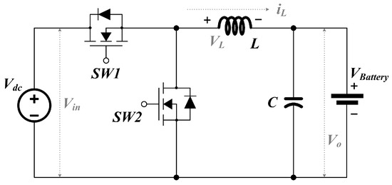
Figure 3.
Buck converter configuration for uninsulated charging.
The voltage applied to the inductor of the buck converter, current flowing through the inductor, and flux linkage of the closed bridge have the following relationship:
By applying Kirchhoff’s voltage law (KVL), the inductor voltage can be calculated based on the switching state, and the inductor voltage is expressed as follows.
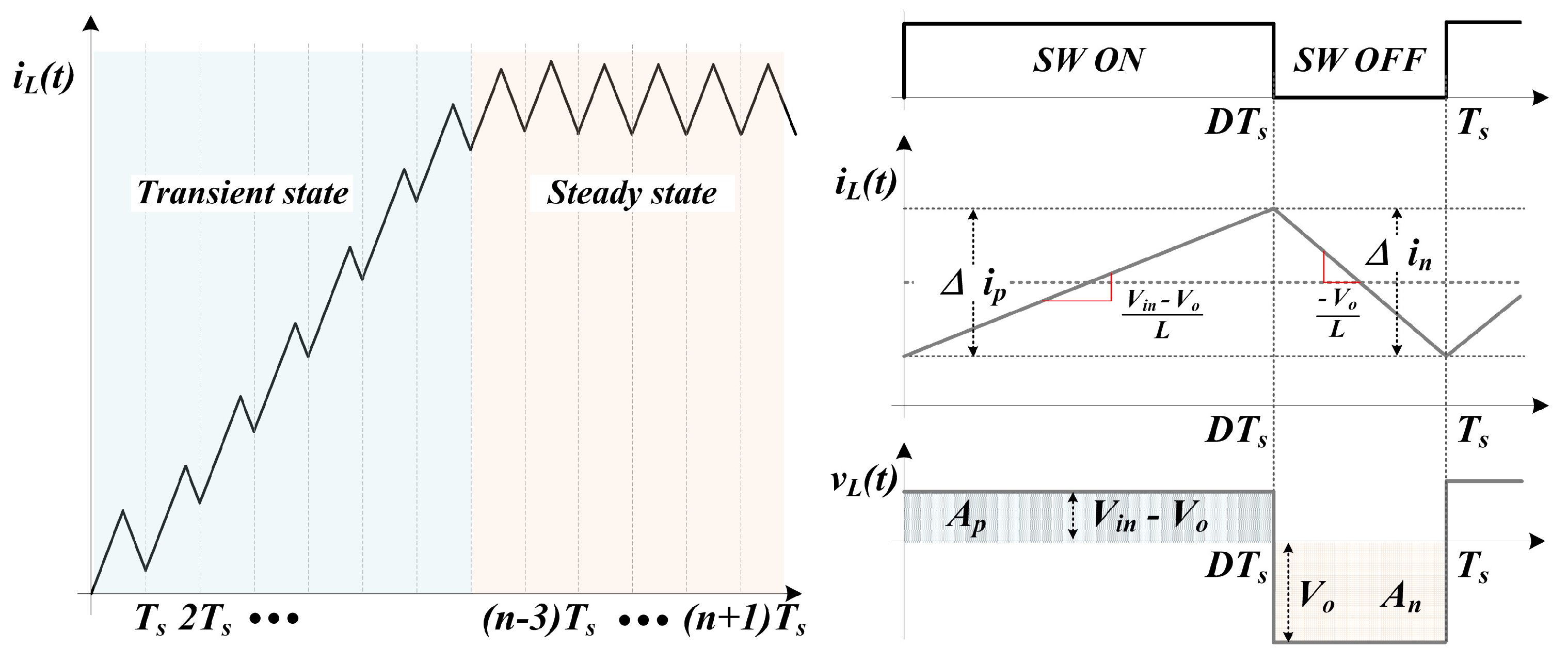
Suppose that the input and output voltages remain unchanged, the slope of the inductor current becomes a constant value. Suppose that the switching period is , the duty ratio is D, the time when the switch is turned on is defined as , and the time when the switch is turned off is defined as . If the rise and fall of the current are divided into and , respectively, the relational expression is as follows:
Figure 4 shows the waveform of the transient and steady state of the inductor voltage and current of the buck converter. In the normal state, = ) is established and the integration of the voltage waveform is represented by a rectangular region, and expressed as shown in Equation (4).
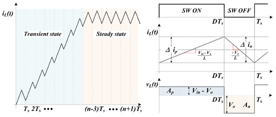
Figure 4.
Inductor voltage and current at the transient and steady state.
Equation (4) is called the voltage second balance law (VSBL), and the input voltage , output voltage , and duty ratio are defined as = × . The inductor can be designed to be in the current continuous mode using the above equation.
In a typical buck converter, , , , L, and C are determined during the design process, and the inductor current is determined only by the duty ratio when controlling the converter [33,34,35,36].
2.2. Transient High-Speed Current Controller Operation Concept
In the aforementioned VSBL state, the energies charged and discharged in the inductor are the same, and the charge current is controlled at a constant value, resulting in an average steady-state operation state. In this case, the duty ratio of the PWM can be determined by the relationship between the input and the output voltages. However, the VSBL is not established in a transient state where the voltage or current changes. Therefore, the duty ratio is controlled using a feedback controller such as a PI controller. PI controllers are widely used and have proven performance; however, they have the disadvantage of difficulty in ensuring control stability due to the overshoot characteristics of the transient state caused by rapid disturbances or system parameter fluctuations. To compensate for this, THSC has recently been studied as a method to reduce overshoots and improve responsiveness in transient sections while maintaining a simple control structure. The THSC is a controller that can increase responsiveness by calculating the flux linkage of the inductor and applying an excitation voltage without PWM switching, allowing instantaneous settling from the transient state to the control current target point. Assuming that the small ripple voltage contained in the input and output voltages is negligible and the voltage value remains unchanged, the inductor current increase during the SW1 ON time in Equation (3) can be determined by calculation. This implies that the SW1 ON time required to reach the control current target point can be known. By continuously turning the switch on for the calculated time, it is possible to quickly reach the average steady-state operation without control in the form of an open loop in the transient state.
When charging begins, the charge current command value is set to a constant current value, the value of the inductor is a value determined by the design, and the input voltage and the output voltage can be detected by sensing. Therefore, the flux linkage required to reach the charging current command value can be calculated and the time to apply the excitation voltage without PWM switching can be defined as the target arrival time .
The target arrival time is calculated using Equation (6) when the current command value changes. The calculated target arrival time is reduced by for each control cycle. The means the target arrival time remaining in the current control loop; under the ≥ condition, duty ratio D is maintained at 1 (SW1 ON). Conversely, under the < condition, it is switched to a PI controller containing a feedforward term for stable control near the control target point. Therefore, the THSC maintains SW1 ON without PWM for a calculated time in the transient state section to quickly increase the target’s current value and controls a stable steady state by converting it to a PI controller that includes a feedforward term at the time of target arrival.
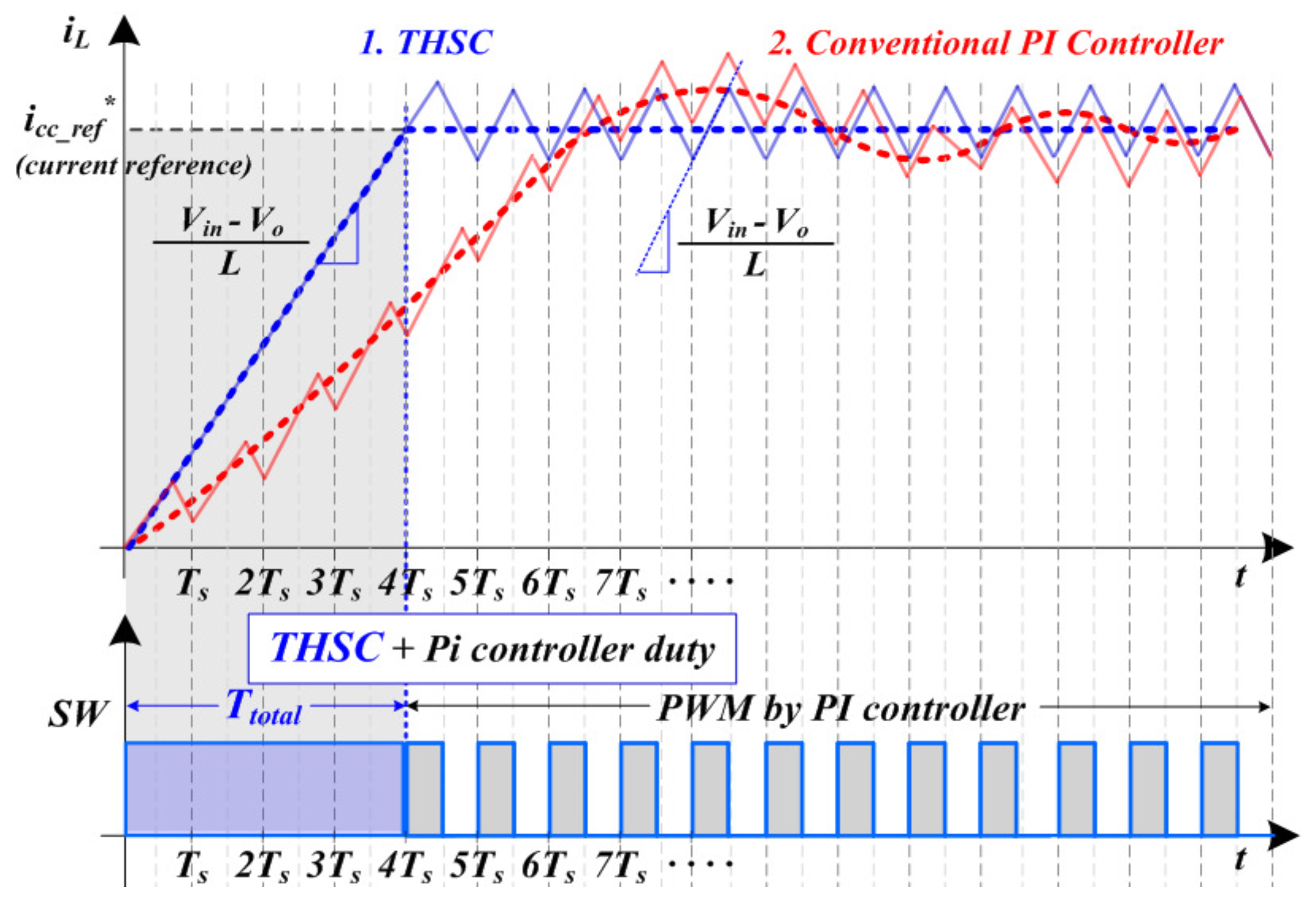
The current waveforms and switching patterns used to compare the response characteristics of THSC and conventional PI controllers are depicted in Figure 5. The PI controllers, marked with red dotted lines, have response characteristics determined by the P and I gain, as well as system components. If the gain is adjusted to increase responsiveness in the transient section and the duty ratio is significantly increased, it becomes difficult to ensure control stability due to overshoot. However, when the gain is set to reduce overshoot, the responsiveness decreases. The THSC, marked with a blue dotted line, maintains the SW (switch) on state until the target current value is reached, continuously increasing the current. It is then switched to the PI controller from the end of the target arrival time to perform linear control. In the transient section, the rising slope of the current is determined by the inductor, input voltage , and power voltage , and is the same as the slope of the inductor current when the switch is ON in the steady-state section.
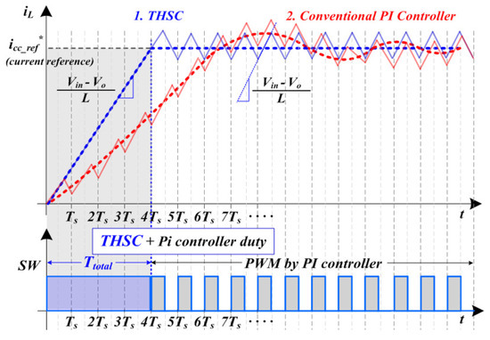
Figure 5.
Response characteristics of a transient high-speed controller.
As such, the THSC can calculate the target arrival time for the target value of the control current; thus, it can quickly reach a normal state without error correction in the transient section to ensure stable control. However, if the parameters required to calculate the target arrival time change in the transient state section, an error in the target arrival time may occur. When the DC power is unstable, a variation in the input voltage may occur. Additionally, the inductor value may become nonlinear depending on the current value, or there may be an error between the design value and the actual applied inductor [37,38]. If the applied inductor value is larger than the set inductor value, undershoot may occur when THSC finishes before the target current point and switches to PI control. Conversely, if the actual inductor value is smaller than the applied inductor value, overshoot occurs because the operation time of THSC is maintained even after the target current point. The greater the variation in these parameters, the more likely it is to affect the responsiveness and stability of the control. This can be fatal in the proposed system where discontinuous charging occurs frequently for a short period of time. Accordingly, a method that maintains the simple control structure of the existing THSC and ensures responsiveness and stability is required.
3. Proposed Control Method
Transient High-Speed Tracking Current Controller
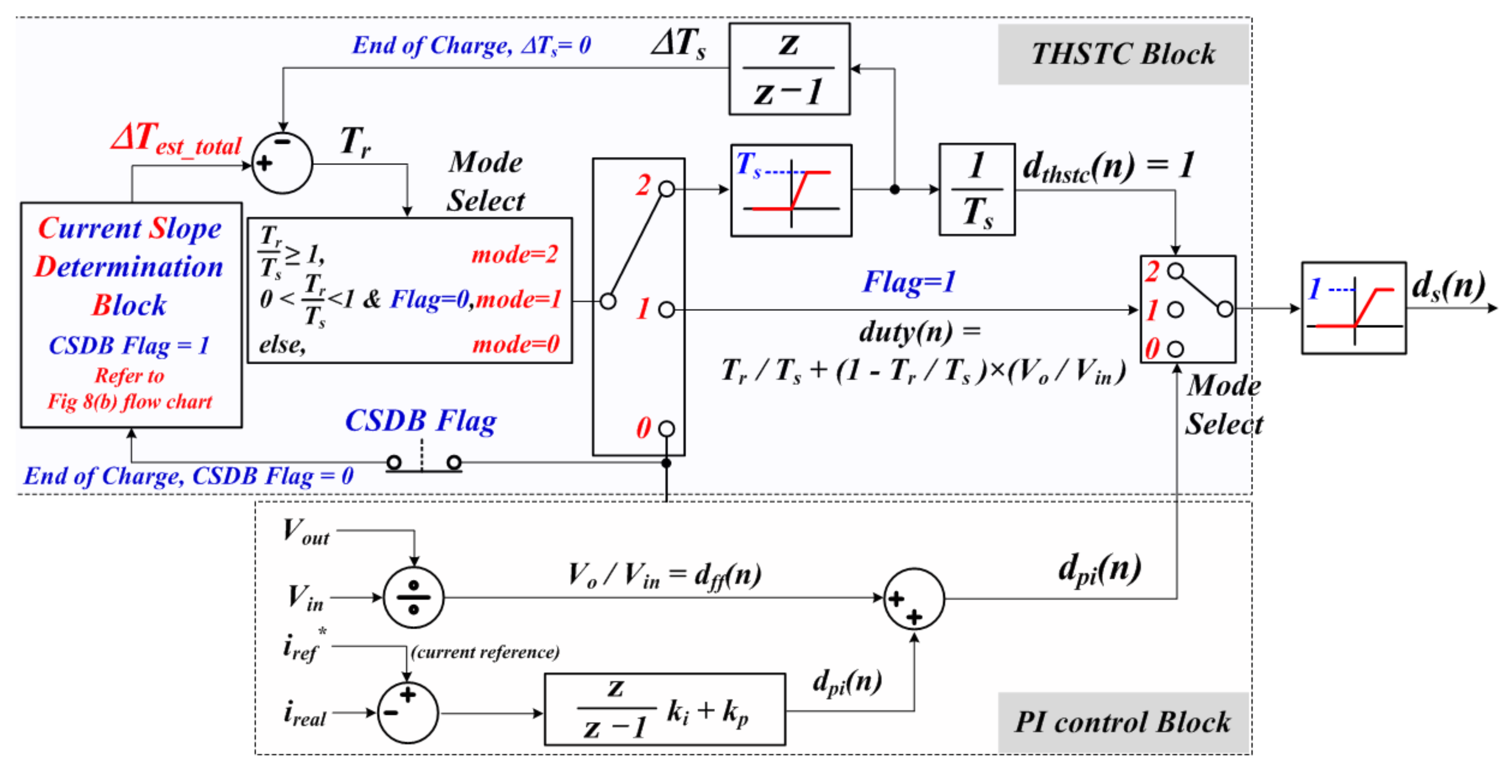
The THSC can improve responsiveness in a transient state by calculating the target arrival time whenever the current command value changes and applying the inductor’s excitation voltage during the target arrival time. However, owing to the structure of the ESS shown in Figure 2, the DC power may be unstable in the transient state where charging begins. In addition, the parameters may vary because of the aforementioned inductor. Consequently, the error between the inductor current value and the target value may increase during the calculated target arrival time . As the inductor current increased by the THSC is less than the current target value, the responsiveness decreases, and in the opposite case, the overshoot increases, making it difficult to ensure control stability in the section converted to the PI controller. This can be a major disadvantage in a discontinuous charging system in which charging starts and ends repeatedly for a short time. Therefore, it maintains the advantages of the existing THSC and proposes a transient high-speed tracking controller (THSTC) suitable for the proposed ESS system. THSTC is a method for tracking the target arrival prediction time by increasing or decreasing by according to the slope of the inductor current without applying the calculated .
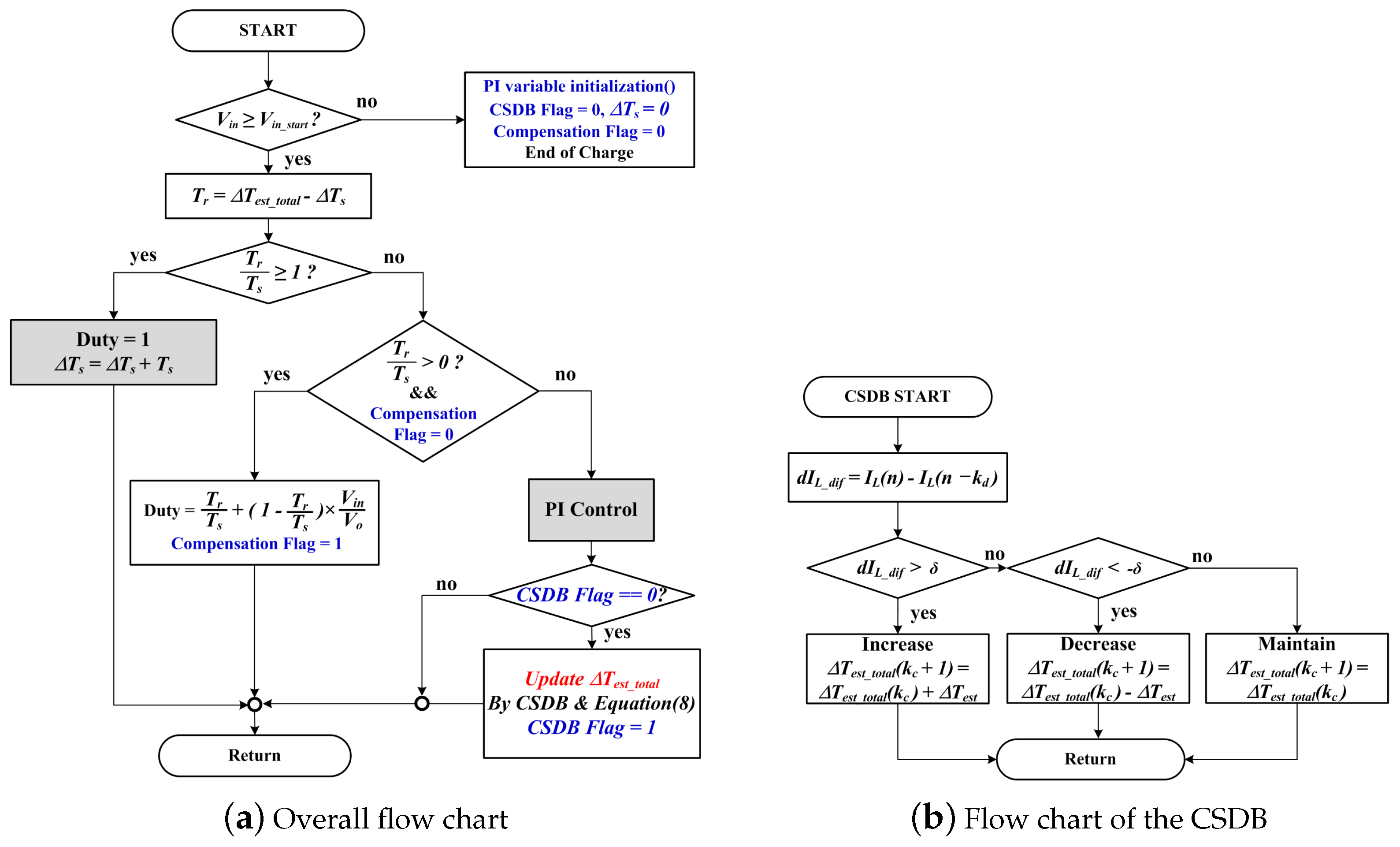
The block diagram of the proposed controller is shown in Figure 6. The overall composition of the controller is divided into a THSTC in the transient state and a PI controller containing a feedforward term for stable control in the normal state. When charging begins and the controller operates, the order is as follows.
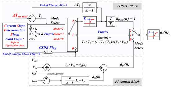
Figure 6.
Transient high-speed tracking current controller block diagram.
Step 1, if the controller is initially executed, the initial value of the target arrival prediction time is zero. refers to the remaining operation time of the THSTC block and is defined as − . The is the control time(equal to sampling time), the initial value of is zero, and increases by every control cycle while the THSTC block is maintained. The PI controller in Mode 0 operates according to the mode selection conditions and the current slope determination block (CSDB) is executed once. At this time, the CSDB updates to value. When the charging is completed, the flag variables and various control variables including are initialized; is not initialized and maintains the current value.
Step 2, the CSDB increases the value as the charging start and end are repeated, and the THSTC operates when the condition is satisfied. While the THSTC is operating, the duty ratio becomes 1 and the SW remains ON. Whenever the control cycle is repeated, is reduced in units of , and when the 0 < condition is reached, the controller operates in Mode 1 by the mode select. This mode compensates by applying the remaining time less than to the duty ratio. In the next control cycle, the PI controller in Mode 0 operates by mode select, and when charging is complete, various variables except are initialized.
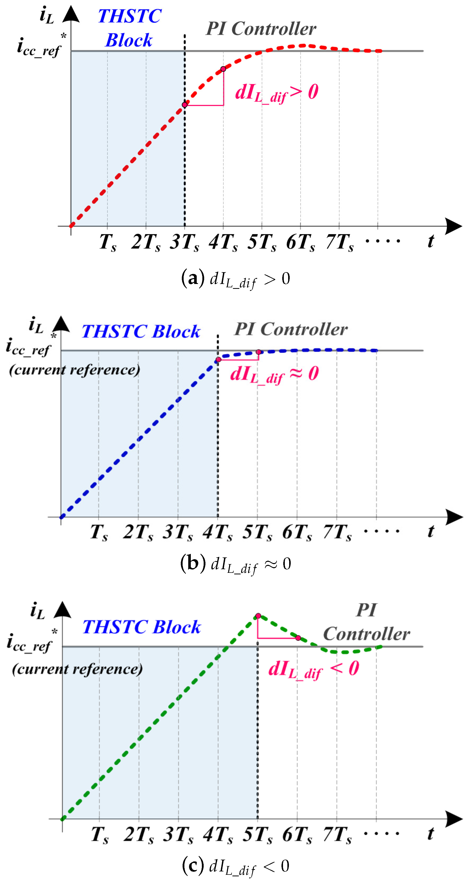
The THSTC tracks the optimal target arrival prediction time while repeating this operation, and the block that determines the optimal target arrival time and changes the value is CSDB. The CSDB executes only once when the PI controller operates in Mode 0. The purpose of the CSDB is to determine whether the PI controller is in the transient state section or close to the steady-state operation based on the slope value of the inductor current when operating PI controller, and to update the value.
The CSDB operation is as follows: represents the slope of the inductor current after the target arrival prediction time . A positive indicates that the inductor current has not reached the target current value and should be increased. Conversely, a negative indicates that the inductor current exceeds the target current value and should be reduced. As the value is optimally estimated, the inductor current approaches the target current value after the end of the THSTC, and converges to a value close to zero.
Figure 7 shows the inductor current slope according to the target arrival prediction time. As aforementioned, when the PI controller operates, the slope of the inductor current is different according to the target arrival prediction time. is a variable for increasing or decreasing ; the smaller the value, the more stably the optimal can be tracked. However, many charging cycles are required to attain this optimal value. represents a small positive value as a reference value for determining the slope of the current, and selects an appropriate value based on the characteristics of the system. The target arrival prediction time using the CSDB is determined using Equation (7).
where denotes the current charging time point, and denotes the time point at which the current charging ends and the next charging starts. value updated using Equation (7) is applied when charging starts again after charging is over. In this way, the optimal target arrival prediction time is estimated while increasing or decreasing by based on .
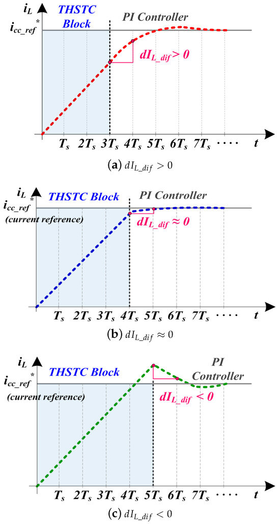
Figure 7.
Inductor current slope according to .
The overall flowchart of the operation of the proposed controller in Figure 6 is shown in Figure 8a. Because the availability of the charging varies, depending on the position of the elevator car, we first determine whether the input voltage is greater than the charging start voltage . When it is in a chargeable state, the THSTC operates when the condition is reached. While is equal to or greater than , SW remains ON, and and are changed every switching period. THSTC ends when is less than . Suppose that the remaining value is ignored. In that case, the smaller the inductor value, the greater the inductor current error near the target current value. To compensate for this, the remaining and the feedforward term are utilized to calculate the duty ratio, which is then used for PWM switching. After the control cycle, the controller is converted to the PI controller. The duty ratio, which compensates for the error, is expressed as:
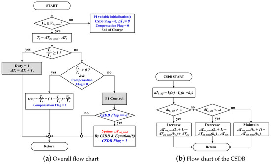
Figure 8.
Transient high-speed tracking current controller flow chart.
A flowchart of the CSDB is shown in Figure 8b. The operating principle is similar to maximum power point tracking (MPPT). After the THSTC terminates, the current detection sampling point to calculate is selected based on the responsiveness of the PI controller. As aforementioned, the CSDB compares and and executes one of three operations: increasing, decreasing, or maintaining . Whenever charging is completed and restarted, the controller is repeatedly operated according to the aforementioned flowchart and the value tracks the optimal value that can reach the target current value .
4. Simulation and Experiment
4.1. Simulation
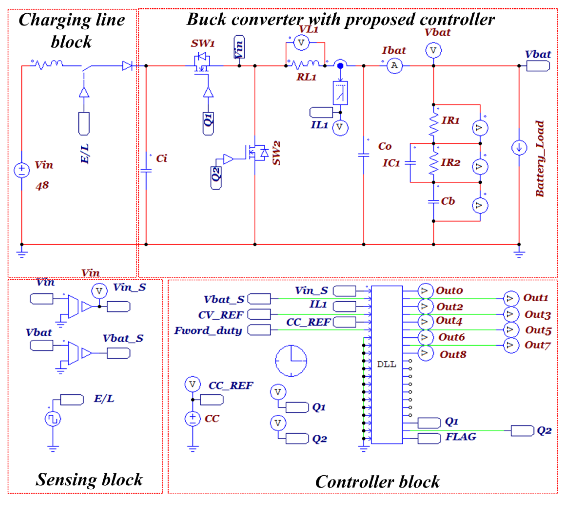
The simulation circuit diagram to verify the validity of the proposed THSTC is shown in Figure 9. The simulation consisted of a charging line, buck converter, and controller. The purpose of the simulation is to verify that the transient state is improved by THSTC when the charging start and end are repeated for a short time by simulating similar to the proposed ESS charging system. A switch circuit was configured to turn the input voltage ON/OFF every 20 ms cycle to simulate a repeated discontinuous charging state. To simulate line impedance, 0.01 Ω of line resistance and 1 μH of line inductance were added. The power-side battery uses a Randles model, and the parameters used in the simulation are listed in Table 1.
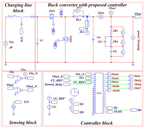
Figure 9.
Simulation circuit diagram.

Table 1.
Specifications and simulation circuit parameters.
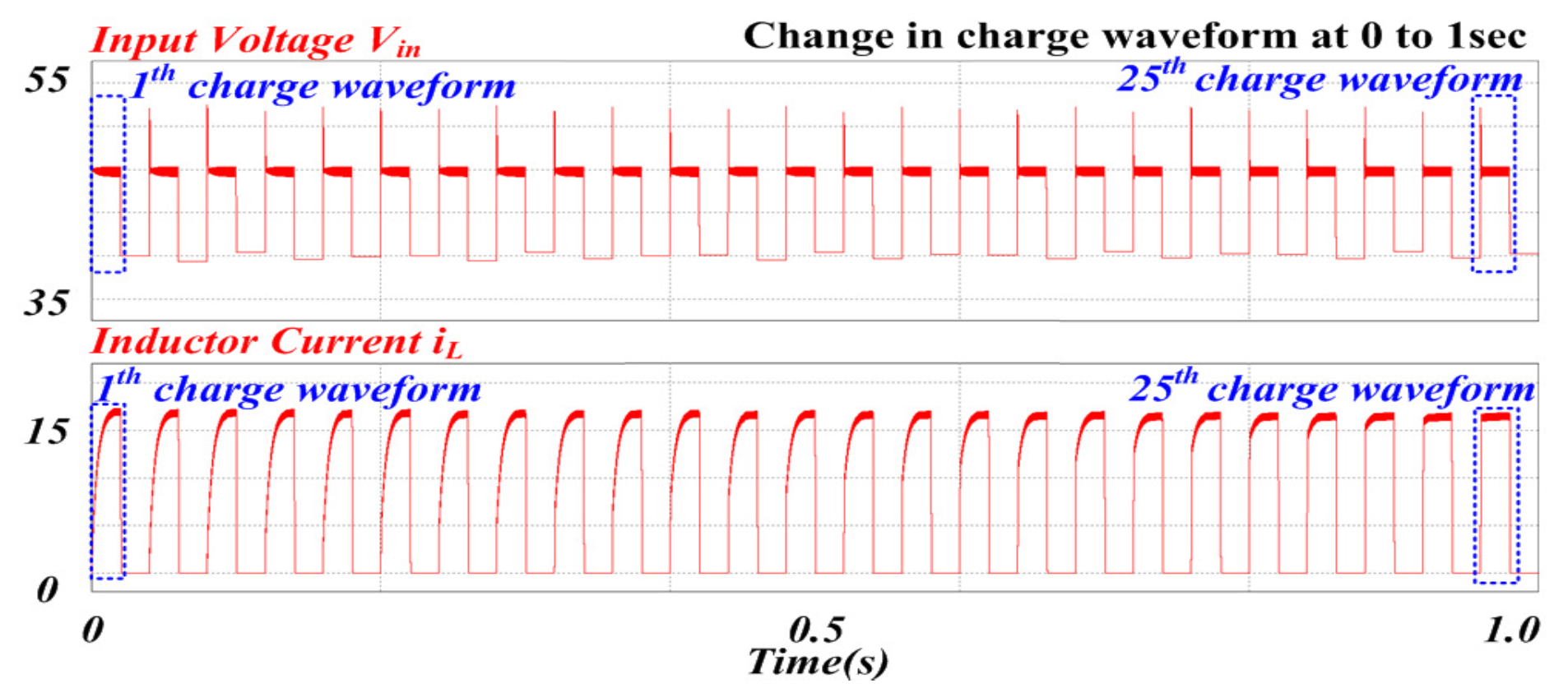
Figure 10 shows the simulation results that confirmed that the transient state of the charge–current waveform was improved as charging was repeated when the proposed algorithm was applied. In the simulation condition, the start and end of charging were repeated every 20 ms, and was applied with a value of × 0.505, which is a value corresponding to approximately 85% of the feedforward term. Although a peak voltage of approximately 7.5 V occurs at the input voltage when charging begins, the response characteristics in transient states gradually improve as the charging number increases.
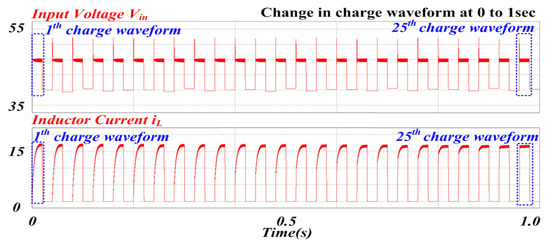
Figure 10.
Charging current change applying the proposed controller.
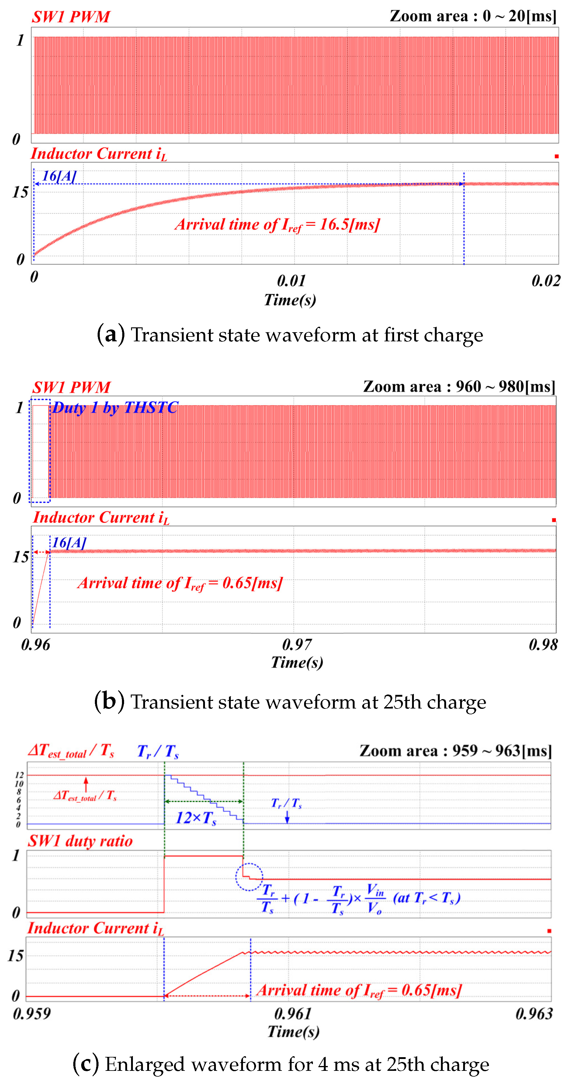
Figure 11 presents a waveform comparison between the initial charging current ( = 0) and the optimized 25th charging current. This comparison is intended to confirm that the proposed controller, as outlined in the controller block depicted in Figure 10, operates on the 25th charging.

Figure 11.
Transient state waveform with change.
The inductor current and PWM output waveform in the transient state of the first charge cycle are shown in Figure 11a. The waveform in the transient state of the 25th charge cycle is shown in Figure 11b. The two waveforms were compared and analyzed at the same time-base of 20 ms. In Figure 11a, the value of is zero; thus, PWM is generated by the PI control without the operation of the THSTC and approximately 16.5 ms is required to reach the target current value (16A). Figure 11b shows that the was increased by CSDB to operate the THSTC block and then the steady-state control was stably performed by the PI controller in Mode 0. The target current value(16 A) was reached at 0.65 ms, which significantly improved the responsiveness and stably controlled without overshoot.
Figure 11c shows a waveform obtained by enlarging the 25th charging current waveform to 4 ms to confirm the change in the value and the value. The red waveform of the first waveform represents with a value of 12.12. This means that the value has steadily increased by during the 24 times repeated discontinuous charging. Even after the THSTC block was terminated and the CSDB algorithm was executed, maintained a constant value, indicating that the slope of the inductor current was within the error of the steady-state current, indicating that the value had been tracked to the optimal value. The blue waveform represents the value of . When the THSTC block was operated in Mode 2, was reduced by for each switching period. During 12 in which the ≥ condition was maintained, the THSTC block was operated and SW1 maintained an ON state.
The second waveform in Figure 11c shows the duty ratio of SW1. When the THSTC block was terminated, the value became 0.12 and operated in Mode 1 on the next control loop by mode select. The part indicated by the blue dotted colored circle indicates that duty ratio compensation was applied using the remaining value in Equation (8). This compensation value was applied during one control loop and had a duty ratio of 0.633.
The third waveform is an enlarged inductor current, and as confirmed in the Figure 11b waveform, the time to reach the target current of 16 A was 0.65 ms and was stably controlled without overshoot.
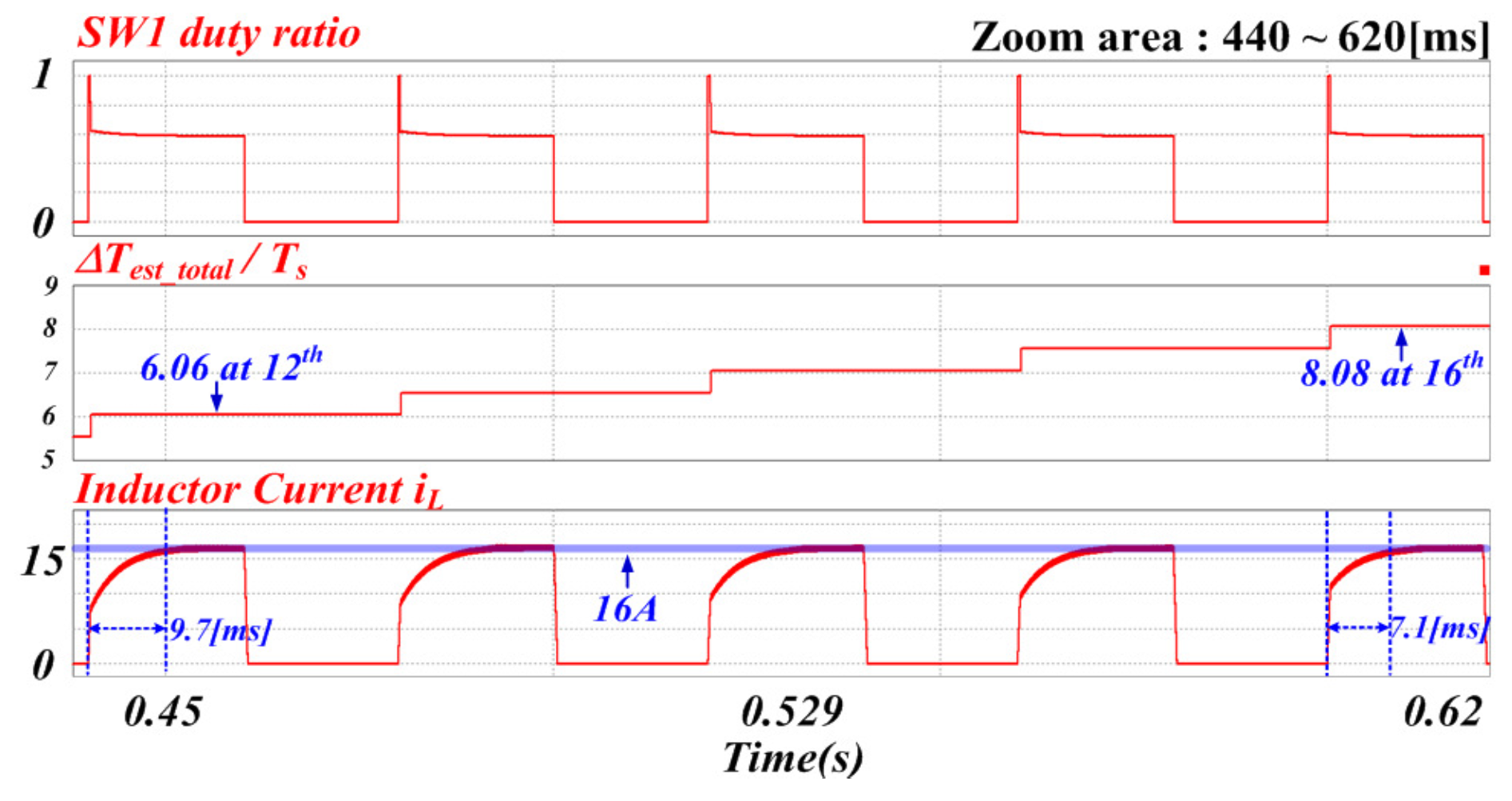
Figure 12 is an enlarged simulation result from the 12th to the 16th charge, detailing the transient state change of the value and the charging current. The first waveform represents the duty ratio of SW1, which transitioned from the THSTC to the PI controller. In the average steady-state operation, the duty ratio was approximately 0.58996. The second waveform shows the value, which was 6.06 in the 12th charge cycle, with the THSTC block operating for 0.3 ms. It is observed that the value of increased as discontinuous charging repeated; in the 16th cycle, the waveform value was 8.08, and THSTC operated for 0.4 ms. The third waveform checks the change in the transient characteristics of the inductor current. It was confirmed that the arrival time of the target current value was 9.7 ms in the 12th charging cycle, and the transient responsiveness continued to improve, reaching 7.1 ms in the 16th charging cycle.
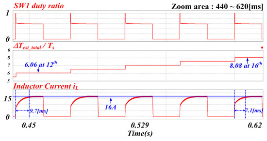
Figure 12.
Transient response characteristics during the 12th to 16th cycles.
Figure 13 shows the results of comparing the transient characteristics of three controllers, PI controller, PI controller with anti-windup, and THSTC, after changing the PI gain so that the duty ratio is maintained at 1.0 until the target value is reached. THSTC uses the same pi gain as before, and the gain values for the other two controllers are = 0.0342, = 60, and = 30. The first waveform shows the inductor current of the PI controller and the PI with anti-wind-up controller. The time to reach the target value for both controllers is the same at 0.65 ms, but the difference is in the magnitude of the overshoot. At the maximum overshoot point of the two controllers, the current difference is about 1.5 A. The second waveform shows the results of PI with anti-wind-up controller and THSTC. Although the target arrival time is the same, there is a difference in overshoot and settling time. The third waveform shows the result value of anti-wind-up. This value is the controller result over the limit value multiplied by the gain. It can be seen that it occurs in the transient region and acts to lower the overshoot. As a result of comparing the three controllers, it can be confirmed that THSTC, which estimates the optimal time, maintains the duty ratio at 1 up to the target value even with a low PI gain and is stably controlled without overshoot in the normal state.
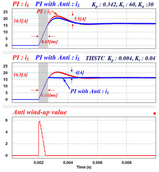
Figure 13.
Simulation results comparing three controllers.
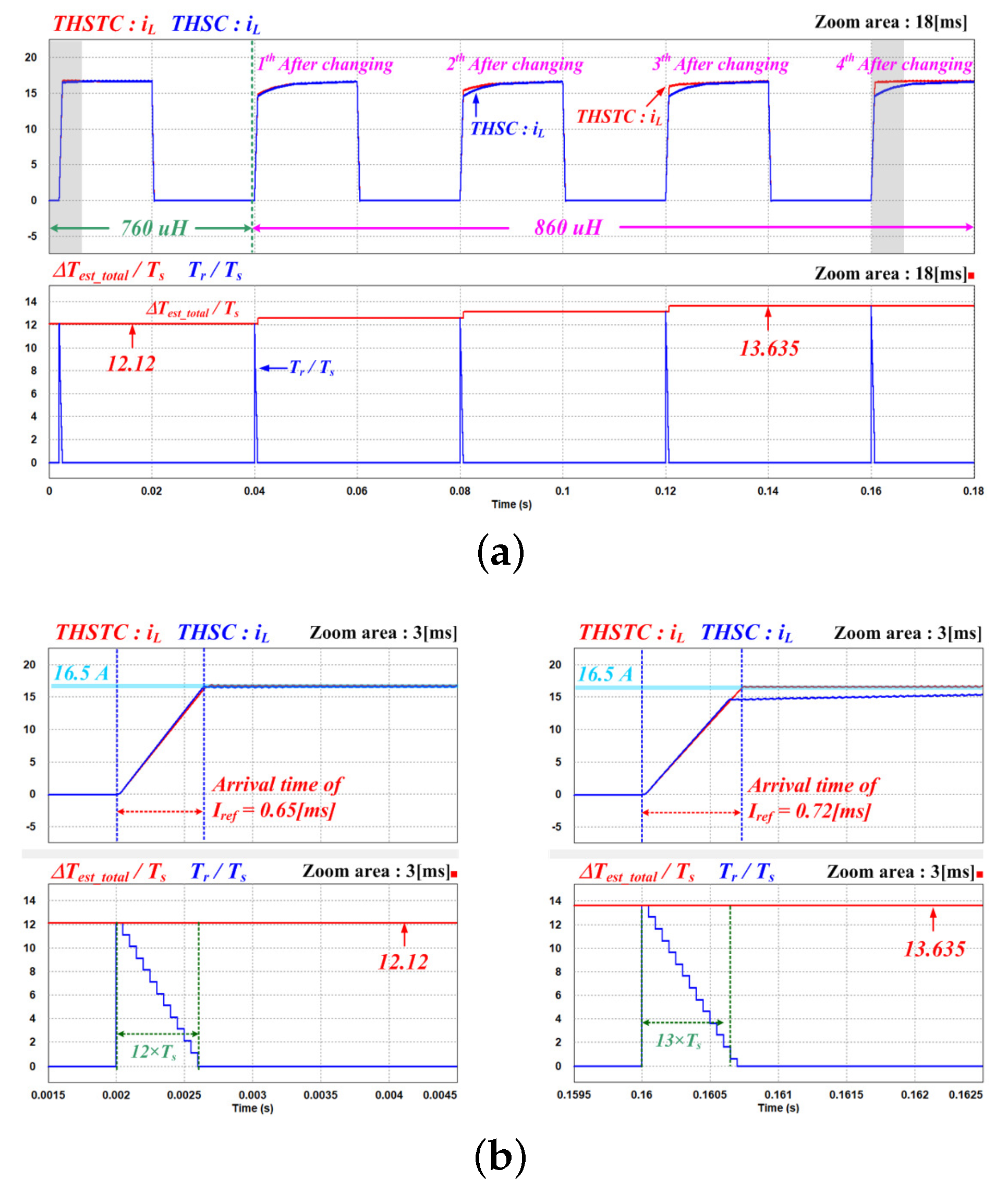
Figure 14 shows the simulation results for comparing the characteristics of the conventional THSC and the proposed THSTC as a function of inductor variation. The inductor value changes from 760 μH, the same as before, to 860 μH at about 40 ms. The first waveform in Figure 14b represents the inductor current of the two controllers. In the first charge with no change in inductor value, both controllers show excellent characteristics. After the inductor is changed to 860 μH, the THSC executes the PI controller before reaching the target value because the inductor value applied to the calculation is smaller than the actual value. As a result, an undershoot occurs, and the same characteristics are shown in subsequent charging. However, the proposed THSTC continues to increase the value because the slope of the inductor current has a positive value. Accordingly, the transient characteristics are gradually improved, and it can be confirmed that THSTC operates without undershoot or overshoot in the final charging cycle. The second waveform in Figure 14a shows the result of the change in the value and the remaining operation time value of THSTC. It can be seen that after the inductor value is changed, continues to increase and changes accordingly. Figure 14b is an enlarged waveform of the first and last charging waveforms in Figure 14a. In the first waveform, the two controllers show similar characteristics, but in the last waveform, THSC undershoot occurred. THSTC optimally tracked and confirmed that the operation was stable without overshoot or undershoot. The target arrival time of THSTC is 0.72 ms and the value is 13.635, confirming that the duty ratio is maintained at 1 for 13Ts.
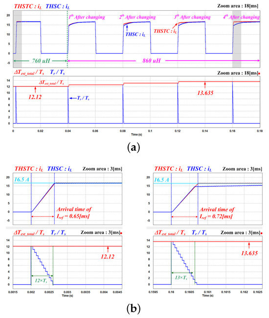
Figure 14.
Two controller simulation results according to inductor change. (a) Change in characteristics of 2 controllers over the charge cycle after the inductor change. (b) Waveforms of the first and last results zoomed in for 3 ms.
4.2. Experiment
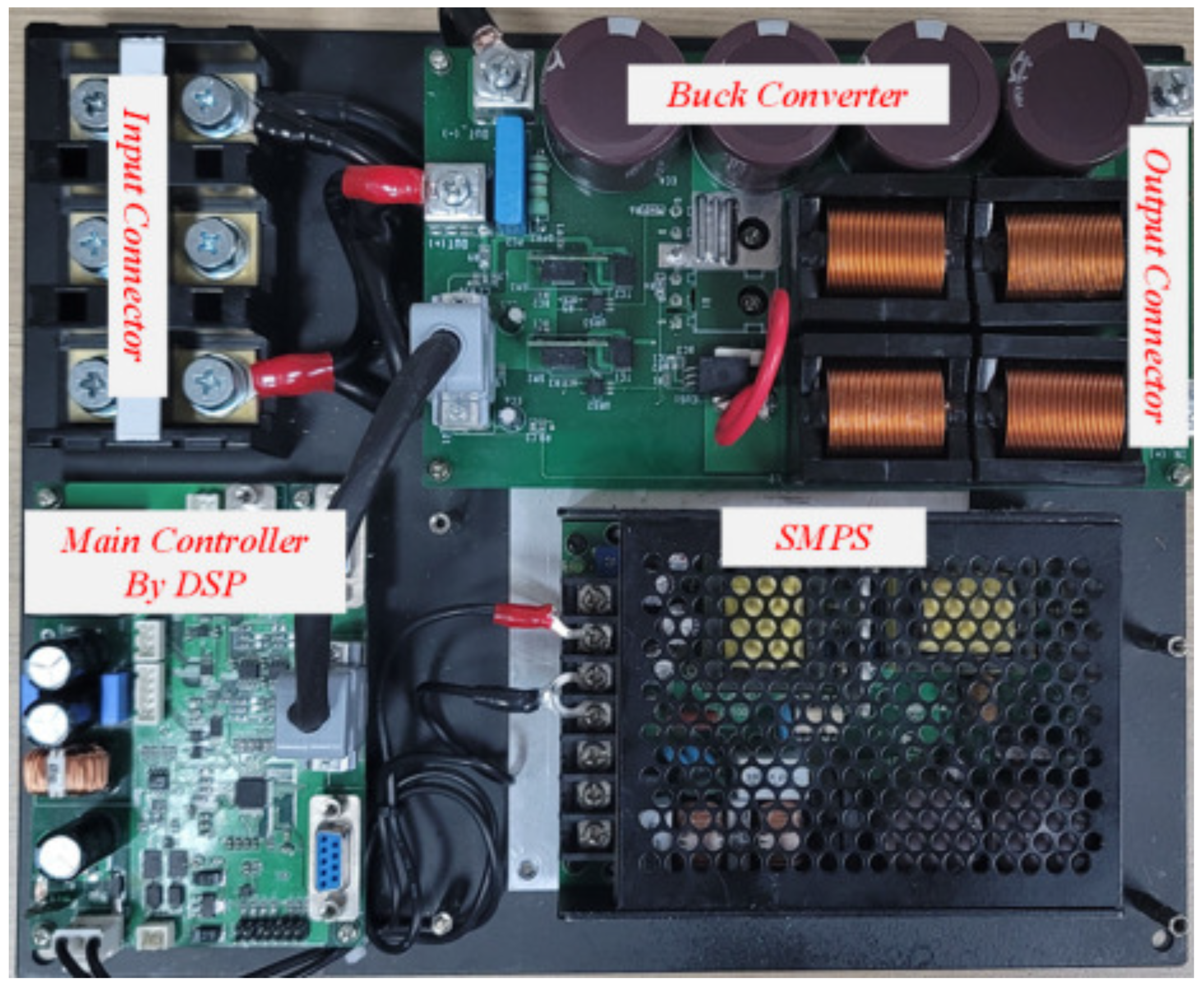
The buck converter system used to validate the proposed THSTC is shown in Figure 15. The microprocessor implemented a control board using TMS320F280025 (Texas Instruments, Dallas, TX, USA) and a relay on the input terminal was used to repeat the start and end of charging. Considering the relay operation time, the charging cycle was set to 500 ms. The parameters applied to the system are listed in Table 2.

Figure 15.
Experimental prototype of the buck converter.
Table 2.
Specifications and parameters of the experimental circuit.
The experiment was conducted under two conditions. The first experiment was conducted to verify the operating characteristics of the THSTC under conditions similar to those of the simulation and to verify that the target arrival time was tracked during repeated discontinuous charging. The second experiment involved changing the conditions and comparing the transient characteristic change in the charging current by THSTC in continuous waveforms using oscilloscopes.
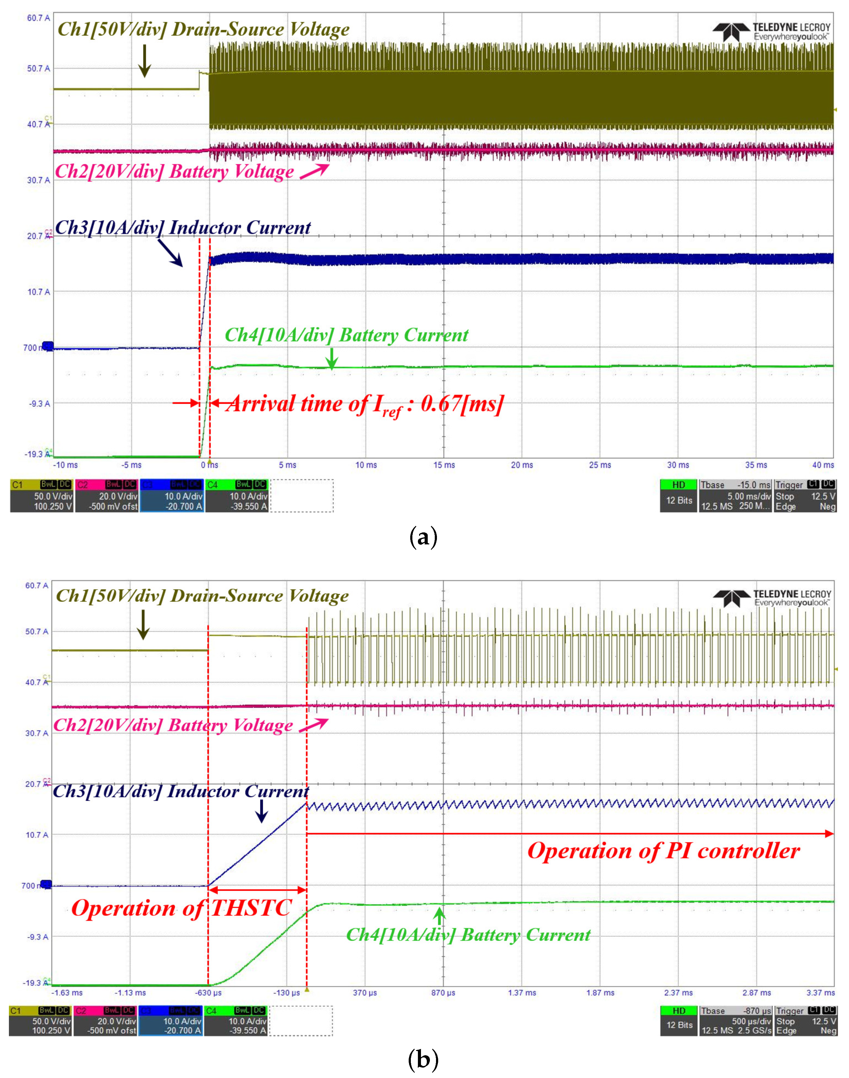
Figure 16 shows the experimental waveform, confirming the operating characteristics of the first charge cycle in which the buck converter was operated. The purpose of the experiment is to check whether can be well-tracked by repeating the charging start and end under conditions similar to the simulation. Ch1 Ch2, Ch3, and Ch4 represent the drain-source voltage of the SW2, output-end battery voltage, inductor current, and battery current, respectively. The results show that the initial value was zero, and the THSTC block did not operate, and PWM control by the PI controller operated; the steady state (16 A) was reached within approximately 17 ms.
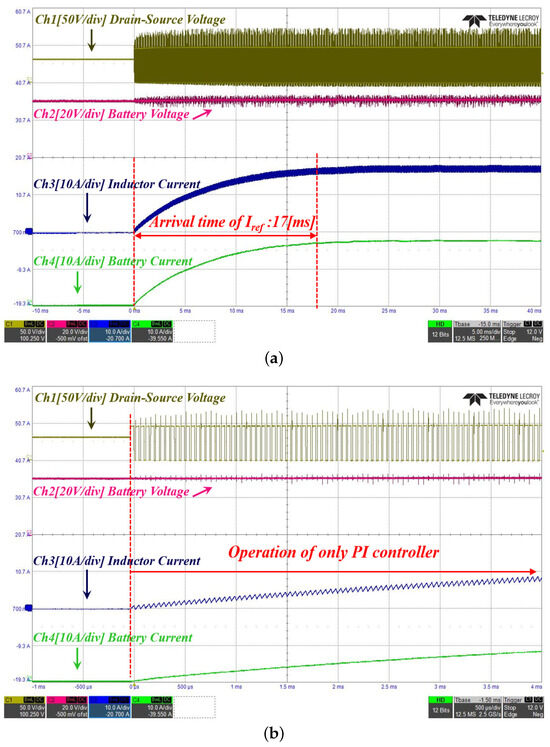
Figure 16.
Transient state waveform at the 1st charge cycle: (a) timebase: 5 ms/div; (b) timebase: 500 μs/div.
Figure 17 shows the experimental waveform confirming the THSTC operation characteristics at a time point after a certain period after discontinuous charging is repeated. As shown in Figure 17a, the time for the inductor to reach the current command value of (16 A) was 0.67 ms, which significantly improved the response compared to the operating characteristics of the first charge current. In Figure 17b, looking at the voltage of Ch1, it was confirmed that SW1 continued to turn on in the transient operation section. It can be seen that when the THSTC was terminated and switched to the PI controller, it operated stably without overshoot. Through the first experiment, Figure 16 and Figure 17, it can be confirmed that transient response characteristics similar to the simulation results appear.
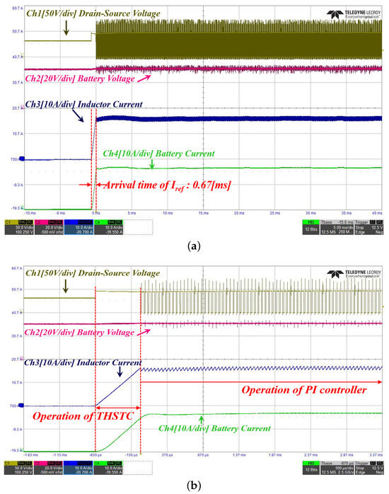
Figure 17.
Transient state waveform of the charge cycle with an optimized : (a) timebase: 5 ms/div; (b) timebase: 500 μs/div.
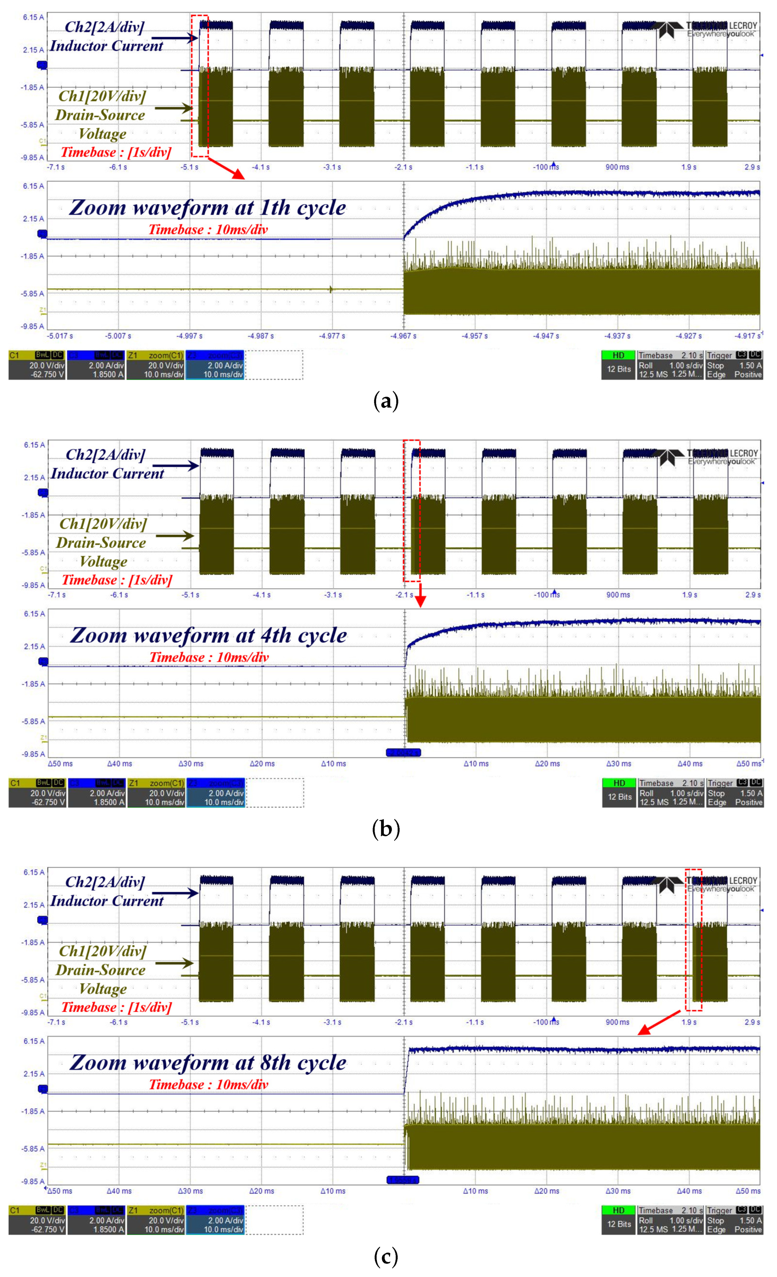
As shown in Figure 18, an experiment was conducted to validate the trend of improving the transient response as discontinuous charging was repeated. The current command value was changed to 5 A to confirm the change in the transient characteristics of the THSTC according to the charging period on one screen of the oscilloscope. Figure 18a shows an enlarged current waveform at the first charge, confirming that PWM switching was operated by the PI controller without THSTC operating. Figure 18b is an enlarged current waveform during the fourth charging cycle, confirming that the THSTC was operated due to the increased ; however, the THSTC terminated before reaching the target current value of 5 A. Subsequently, the PI controller was operated. Figure 18c is an enlarged current waveform during the 8th charge. Compared with Figure 18a, it was confirmed that the inductor current increased rapidly to the target current value (5 A) by optimizing and stably switching without overshoot at the time when the PI controller operated.

Figure 18.
Changes in the transient state waveform with an increasing charge cycle: (a) first cycle (timebase: 1 s/div (zoom 10 ms/div)); (b) fourth cycle (timebase: 1 s/div (zoom 10 ms/div)); (c) eight cycles (timebase: 1 s/div (zoom 10 ms/div)).
5. Conclusions
This study presented a novel elevator system structure with a small ESS and proposed a suitable controller. The effectiveness of the proposed controller was validated through simulations and experiments. The THSTC used the concept of THSC, which reached the target current value by applying an inductor’s excitation voltage without PWM switching. At this time, the optimal time applied was a method of tracking the target arrival prediction time by the CSDB algorithm rather than the conventional method by calculation.
If the DC power is unstable during the transient section or parameter fluctuations including inductor occur, the conventional THSC may have an error when switching to the PI controller. The proposed controller can maintain a simple control structure and ensure responsiveness and stability by using frequent discontinuous charging and constant current command value in the current charging mode. With the accelerating activation of distributed resources, the use of various types of DC power systems has increased. The proposed controller does not require a complicated design and has a simple control structure with excellent dynamic properties; therefore, it is expected to have a significant effect when used in systems with repeated discontinuous charging.
Author Contributions
Conceptualization, J.-H.L. and J.-H.P.; methodology, S.-K.L.; software, J.-H.L., C.H. and J.-H.P.; validation, H.-S.J. and K.-B.H.; formal analysis, J.-H.L. and S.-K.L.; investigation, H.-S.J. and C.H.; data curation, J.-H.P. and S.-K.L.; writing—original draft preparation, J.-H.L. and S.-K.L.; writing—review and editing, J.-H.L. and J.-H.P.; Funding acquisition, H.-S.J. and K.-B.H.; Project administration, H.-S.J. and J.-H.P. All authors have read and agreed to the published version of the manuscript.
Funding
This research was supported by the Stratospheric Drone Technology Development Program through the National Research Foundation of Korea (NRF) and Stratospheric Drone Technology Development Center funded by the Ministry of Science and ICT, the Republic of Korea (grant no. 2022M3C1C7090617).
Data Availability Statement
The data presented in this study are available in this article.
Conflicts of Interest
The authors declare no conflict of interest.
Abbreviations
| THSC | transient high-speed current controller |
| THSTC | transient high-speed tacking current controller |
| the target arrival time by calculating in THSC | |
| CSDB | current slope determination block |
| the target arrival time by CSDB in THSTC | |
| variable for increasing or decreasing | |
| the remaining operation time of the THSTC block | |
| control time (equal to sampling time) | |
| increases by every control cycle while the THSTC block is maintained | |
| the slope of the inductor current | |
| the current charging time point | |
| small positive value |
References
- Lau, K.K.L.; Chung, S.C.; Ren, C. Outdoor thermal comfort in different urban settings of sub-tropical high-density cities: An approach of adopting local climate zone (LCZ) classification. Build. Environ. 2019, 154, 227–238. [Google Scholar] [CrossRef]
- Yuan, M.; Yin, C.; Sun, Y.; Chen, W. Examining the associations between urban built environment and noise pollution in high-density high-rise urban areas: A case study in Wuhan, China. Sustain. Cities Soc. 2019, 50, 101678. [Google Scholar] [CrossRef]
- Qin, H.; Lin, P.; Lau, S.S.Y.; Song, D. Influence of site and tower types on urban natural ventilation performance in high-rise high-density urban environment. Build. Environ. 2020, 179, 106960. [Google Scholar] [CrossRef]
- Hill, I.L.R.; Mangera, M.; Parshotam, D.S.; Panday, A.; Pedro, J.O. Genetic algorithm based design of pid and pdf controllers for velocity tracking of a high-rise building elevator. In Proceedings of the 2018 SICE International Symposium on Control Systems (SICE ISCS), Tokyo, Japan, 9–11 March 2018; pp. 136–143. [Google Scholar]
- Zhang, H.; Zhang, R.; He, Q.; Liu, L. Variable universe fuzzy control of high-speed elevator horizontal vibration based on firefly algorithm and backpropagation fuzzy neural network. IEEE Access 2021, 9, 57020–57032. [Google Scholar] [CrossRef]
- Peng, Q.; Xu, P.; Yuan, H.; Ma, H.; Xue, J.; He, Z.; Li, S. Analysis of vibration monitoring data of flexible suspension lifting structure based on time-varying theory. Sensors 2020, 20, 6586. [Google Scholar] [CrossRef]
- Al-Kodmany, K. Elevator technology improvements: A snapshot. Encyclopedia 2023, 3, 530–548. [Google Scholar] [CrossRef]
- Ballester, C.; Copaci, D.; Arias, J.; Moreno, L.; Blanco, D. Hoist-based shape memory alloy actuator with multiple wires for high-displacement applications. Actuators 2023, 12, 159. [Google Scholar] [CrossRef]
- Qiu, L.; He, C.; Yi, G.; Zhang, S.; Wang, Y.; Rao, Y.; Zhang, L. Energy-based vibration modeling and solution of high-speed elevators considering the multi-direction coupling property. Energies 2020, 13, 4821. [Google Scholar] [CrossRef]
- Peng, Q.; Jiang, A.; Yuan, H.; Huang, G.; He, S.; Li, S. Study on theoretical model and test method of vertical vibration of elevator traction system. Math. Probl. Eng. 2020, 2020, 8518024. [Google Scholar] [CrossRef]
- Wang, G.; Wang, B.; Li, C.; Xu, D. Weight-transducerless control strategy based on active disturbance rejection theory for gearless elevator drives. IET Electr. Power Appl. 2017, 11, 289–299. [Google Scholar] [CrossRef]
- Zhang, Q.; Yang, Y.H.; Hou, T.; Zhang, R.J. Dynamic analysis of high-speed traction elevator and traction car–rope time-varying system. Noise Vib. Worldw. 2019, 50, 37–45. [Google Scholar] [CrossRef]
- Zhang, Q.; Hou, T.; Zhang, R.J.; Liu, J. Time-varying characteristics of the longitudinal vibration of a high-speed traction elevator lifting system. Int. J. Acoust. Vib. 2019, 25, 153–161. [Google Scholar] [CrossRef]
- Anghelache, G.; Nastac, S. Computational analysis of nonlinearities within dynamics of cable-based driving systems. IOP Conf. Ser. Mater. Sci. Eng. 2020, 227, 012007. [Google Scholar] [CrossRef]
- Kumar, R.S.; Swaminathan, G.; Loganathan, G.B. Design and analysis of composite belt for high rise elevators. Mater. Today Proc. 2020, 22, 663–672. [Google Scholar] [CrossRef]
- Zhao, B.; Quan, Z.; Li, Y.W.; Quan, L.; Hao, Y.; Ding, L. A hybrid driven elevator system with energy regeneration and safety enhancement. IEEE Trans. Ind. Electron. 2019, 67, 7715–7726. [Google Scholar] [CrossRef]
- Kermani, M.; Shirdare, E.; Abbasi, S.; Parise, G.; Martirano, L. Elevator regenerative energy applications with ultracapacitor and battery energy storage systems in complex buildings. Energies 2021, 14, 3259. [Google Scholar] [CrossRef]
- Jabbour, N.; Mademlis, C. Supercapacitor-based energy recovery system with improved power control and energy management for elevator applications. IEEE Trans. Power Electron. 2017, 32, 9389–9399. [Google Scholar] [CrossRef]
- Yao, Y.; Sun, Z.; Yang, G.; Liu, W.; Prapamonthon, P. Analysis of aerodynamic noise characteristics of high-speed train pantograph with different installation bases. Appl. Sci. 2019, 9, 2332. [Google Scholar] [CrossRef]
- Mariscotti, A.; Sandrolini, L. Detection of harmonic overvoltage and resonance in AC railways using measured pantograph electrical quantities. Energies 2021, 14, 5645. [Google Scholar] [CrossRef]
- Raviraj, V.S.C.; Sen, P.C. Comparative study of proportional-integral, sliding mode, and fuzzy logic controllers for power converters. IEEE Trans. Ind. Appl. 1997, 33, 518–524. [Google Scholar] [CrossRef]
- Wu, G.; Sun, L.; Lee, K.Y. Disturbance rejection control of a fuel cell power plant in a grid-connected system. Control Eng. Pract. 2017, 60, 183–192. [Google Scholar] [CrossRef]
- Alhejji, A.; Mosaad, M.I. Performance enhancement of grid-connected PV systems using adaptive reference PI controller. Ain Shams Eng. J. 2021, 12, 541–554. [Google Scholar] [CrossRef]
- Mobayen, S.; Bayat, F.; Lai, C.C.; Taheri, A.; Fekih, A. Adaptive global sliding mode controller design for perturbed DC-DC buck converters. Energies 2021, 14, 1249. [Google Scholar] [CrossRef]
- Muñoz-Cruzado-Alba, J.; Villegas-Núñez, J.; Vite-Frías, J.A.; Carrasco Solís, J.M. Adaptive global sliding mode controller design for perturbed DC-DC buck converters. Energies 2015, 9, 1. [Google Scholar] [CrossRef]
- Bibian, S.; Jin, H. High performance predictive dead-beat digital controller for DC power supplies. IEEE Trans. Power Electron. 2002, 17, 420–427. [Google Scholar] [CrossRef]
- Rubio, J.; Figueroa, M.; Pérez Cruz, J.H.; Yoe Rumbo, J. Control para estabilizar y atenuar las perturbaciones en un péndulo invertido rotatorio. Rev. Mex. Física 2012, 58, 107–112. [Google Scholar]
- Sorcia-Vázquez, F.D.J.; Garcia-Beltran, C.D.; Valencia-Palomo, G.; Brizuela-Mendoza, J.A.; Rumbo-Morales, J.Y. Decentralized robust tube-based model predictive control: Application to a four-tank-system. Rev. Mex. Ing. Química 2020, 19, 1135–1151. [Google Scholar] [CrossRef]
- Lee, J.H.; Park, S.J.; Lim, S.K. High-Speed Controller to Enhance Responsiveness and Stability of Dynamic Characteristics for DC-DC Converter. IEEE Trans. Ind. Electron. 2023, 71, 3996–4005. [Google Scholar] [CrossRef]
- Zhang, J.; He, Y.; Hang, L. A novel interleaved parallel cascaded three-level pfc with low inductance volt-second and low common-mode noise. IEEE Trans. Power Electron. 2022, 38, 17–21. [Google Scholar] [CrossRef]
- Chen, H.; Sun, K.; Lu, L.; Wang, S.; Ouyang, M. A constant current control method with improved dynamic performance for cllc converters. IEEE Trans. Power Electron. 2022, 37, 1509–1523. [Google Scholar] [CrossRef]
- Hou, N.; Hu, J.; Mou, D.; Zhang, Y.; Li, Y.W.; De Doncker, R.W. A simple DC-offset eliminating method of the series-inductance current for the dab DC–DC converter. IEEE Trans. Power Electron. 2022, 38, 4224–4228. [Google Scholar] [CrossRef]
- Suh, J.-D.; Seok, J.; Kong, B.-S. A fast response pwm buck converter with active ramp tracking control in a load transient period. IEEE Trans. Circuits Syst. II Express Briefs 2018, 66, 467–471. [Google Scholar] [CrossRef]
- Chen, J.J.; Hwang, Y.S.; Jiang, W.M.; Lai, C.H.; Ku, J. A new improved ultra-fast-response low-transient-voltage buck converter with transient-acceleration loops and V-cubic techniques. IEEE Access 2022, 10, 3601–3607. [Google Scholar] [CrossRef]
- Yanarates, C.; Zhou, Z. Design and cascade pi controller-based robust model reference adaptive control of DC-DC boost converter. IEEE Access 2022, 10, 44909–44922. [Google Scholar] [CrossRef]
- Tang, Y.; Tian, Z.; Zha, X.; Li, X.; Huang, M.; Sun, J. An improved equal area criterion for transient stability analysis of converter-based microgrid considering nonlinear damping effect. IEEE Trans. Power Electron. 2022, 37, 11272–11284. [Google Scholar] [CrossRef]
- Wang, L.; Pei, Y.; Yang, X.; Qin, Y.; Wang, Z. Improving light and intermediate load efficiencies of buck converters with planar nonlinear inductors and variable on time control. IEEE Trans. Power Electron. 2011, 27, 342–353. [Google Scholar] [CrossRef]
- Mastromauro, R.A.; Liserre, M.; Dell’Aquila, A. Study of the effects of inductor nonlinear behavior on the performance of current controllers for single-phase PV grid converters. IEEE Trans. Ind. Electron. 2008, 55, 2043–2052. [Google Scholar] [CrossRef]


Disclaimer/Publisher’s Note: The statements, opinions and data contained in all publications are solely those of the individual author(s) and contributor(s) and not of MDPI and/or the editor(s). MDPI and/or the editor(s) disclaim responsibility for any injury to people or property resulting from any ideas, methods, instructions or products referred to in the content. |
© 2023 by the authors. Licensee MDPI, Basel, Switzerland. This article is an open access article distributed under the terms and conditions of the Creative Commons Attribution (CC BY) license (https://creativecommons.org/licenses/by/4.0/).