Abstract
In order to clarify the magnetic-thermal-force changing rule of high-frequency transformers under different winding arrangements, this paper tests the magnetization and loss characteristics of nanocrystalline materials at different temperatures, and based on the magnetization and loss data, establishes a magnetic-thermal-force coupling calculation model of 15 kVA, 5 kHz nanocrystalline high-frequency transformers, and calculates and analyzes the magnetic flux density, loss and temperature rise distributions of high-frequency transformers with three different winding arrangements under no-load and short-circuit conditions, respectively. Through comparative analysis, it was found that under no-load conditions, the cross-transposition of winding has less influence on the magnetic flux of the high-frequency transformer core, but it can reduce the iron-core loss and transformer temperature rise. The cross-transposition of winding under short-circuit conditions can significantly reduce the leakage magnetic field strength of high-frequency transformers; complete cross-transposition weakens the high-frequency transformer losses and temperature rise better than partial cross-transposition. According to the winding current density and core leakage field distribution under short-circuit conditions, we calculated and analyzed the distribution of its the axial and radial electromagnetic forces. The results show that the axial electromagnetic force causes the winding to be squeezed from both ends to the middle, the radial electromagnetic force causes the primary winding to shrink inward and the secondary winding to expand outward, so cross-transposition can greatly reduce electromagnetic force and weakening the deformation of the winding. Therefore, high-frequency transformers of winding cross-transposed should be used in actual projects to reduce transformer temperature rise and improve efficiency and security. This research has theoretical significance for the multi-physical field coupling of high-frequency transformers and its structural design.
1. Introduction
Magnetic components in traditional power grids are usually large due to their size and weight, causing considerable power losses during energy transmission [1]. With the development of high-voltage direct-current transmission systems and the construction of smart grids, power electronic transformers, due to their smaller size and weight and higher power density, not only have functions such as voltage transformation, isolation and power transmission, but can also achieve power flow control and power quality. With adjustment and other functions [2], they have been widely used in the power grid. However, with the increase in frequency and power, the problems of loss and temperature rise of power electronic transformers, especially high-frequency transformers (HFT), are more prominent. Temperature rise exceeding the threshold will affect the service life and operational safety of the transformer [3]. In addition, the electromagnetic force of the winding of a high-frequency transformer is closely related to the leakage magnetic field and winding current intensity of the transformer, and the mechanical strength of the winding will affect the reliability of the transformer operation [4]. When a short-circuit fault occurs in a power electronic transformer, the maximum short-circuit current of the transformer winding can reach 10 to 20 fold the rated value, and the winding will withstand electromagnetic forces that may cause it to deform or even be destroyed [5]. Therefore, it is crucial to accurately calculate the losses and temperature rise of high-frequency transformers. The analysis of winding electromagnetic forces is also one of the key points that needs attention and research in the design process of high-frequency transformers.
For the calculation of winding losses of high-frequency transformers under non-sinusoidal excitation, the influence of the skin effect and the proximity effect needs to be considered, and the Dowell method can be used [6]. This method uses the AC winding coefficient to characterize the influence of the winding skin effect and the proximity effect, and can more accurately calculate ground winding losses at high frequencies [7]. For the calculation of core loss, the improved Steinmetz empirical formula method can be used. The formula has fewer parameters, is easy to fit, and has high calculation accuracy [8]. The main methods for calculating temperature rise of transformers include the empirical formula method, the thermal network model method and the finite element method [9,10]. The study in [11] established an equivalent thermal circuit model based on the heat dissipation path of the high-frequency transformer, calculated the steady-state temperature distribution and compared it with the finite element simulation, verifying the feasibility of the thermal circuit model method to calculate the temperature rise distribution of the high-frequency transformer. The study in [12] used finite element simulation software to simulate and calculate the transient magnetic field and the temperature field of high-frequency transformers, and designed and manufactured 5 kHz, 10 kVA shell-type and core-type high-frequency transformers, verifying the feasibility of the finite element method. The study in [13] aims at the accurate calculation of the temperature field of medium-frequency transformers under non-sinusoidal excitation, using the calculation method of two-way coupling of transient electromagnetic field and temperature field, and designing a 200 kVA/10 kHz nanocrystalline transformer. Experimental comparisons were conducted with iron-core medium-frequency transformers to verify the effectiveness of the simulation. For the simulation modeling of magnetic components, the study in [14] analyzes the use of SPICE (version 17.2) software for modeling the characteristics of magnetic components such as inductors, coupled inductors, and transformers. The results are of calculations and measurements illustrating the correctness and practical usefulness of the described models.
The magnitude of the winding electromagnetic force is determined by the winding current and spatial magnetic flux density. When calculating the winding electromagnetic force, it is necessary to analyze the leakage magnetic field in the space where it is located. The study in [15] established a three-dimensional finite element model of the transformer, and used a non-linear solution to accurately analyze the three-dimensional leakage magnetic field distribution of the transformer in steady-state and short-circuit conditions. The study in [16] takes a three-phase three-winding transformer as the research object and analyzes the transient leakage magnetic field and maximum magnetic density distribution rules under three winding tapping modes when a short-circuit fault occurs in the medium-voltage side winding. The study in [17] analyzed the leakage magnetic field and electromagnetic force of high-frequency transformers under different winding arrangements based on the finite element method. Cross-transposition can effectively weaken the proximity effect, and the leakage magnetic field intensity and electromagnetic force are significantly reduced. However, the current study does not consider the effect of winding cross-transposition on the temperature distribution of high-frequency transformers.
Based on the magnetization and loss characteristics of nanocrystalline materials at different temperatures, this paper established a three-dimensional finite element calculation model for two-way coupling of electromagnetic and temperature fields of a 5 kHz, 15 kVA high-frequency transformer, we calculated and analyzed the magnetic field of the high-frequency transformer under no-load and short-circuit conditions, loss and temperature rise distribution characteristics, and analyzed the influence of different winding arrangements on leakage magnetic flux, temperature rise and the winding electromagnetic force of high-frequency transformers. Winding cross-transposition can improve its efficiency and safety. The research in this article provides theoretical and data support for the optimal design of high-frequency transformers.
2. Analysis of a Multi-Physics Coupling Model of a High-Frequency Transformer
In the electromagnetic field calculation of high-frequency transformers, the magnetic density loss curve (B–P curve) and magnetization curve (B–H curve) are closely related to the temperature field. Changes in temperature cause changes in the loss characteristics and magnetic characteristics of the transformer, and changes in the loss characteristics and magnetic characteristics It will also affect the distribution of the transformer temperature field. Therefore, the electromagnetic field and the temperature field of the high-frequency transformer are bidirectionally coupled. The calculation process of electromagnetic field and temperature field coupling of a high-frequency transformer is shown in Figure 1. Among them, tm is the electromagnetic cycle calculation time; t1 is the power excitation cycle; t2 is the time required for the thermal field calculation temperature to reach a stable value after the electromagnetic cycle calculation is completed; kw is the number of cycles of coupling calculation.
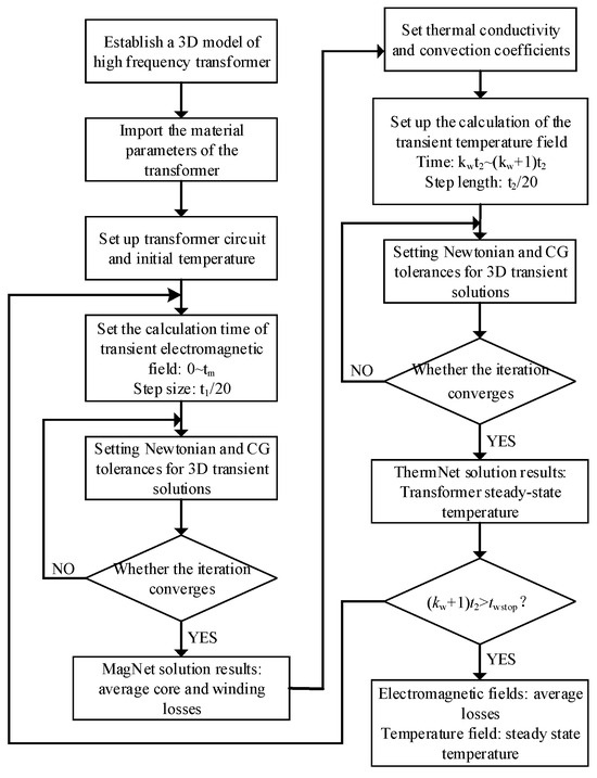
Figure 1.
Flow chat of electromagnetic field and temperature field coupled calculation of a high-frequency transformer.
The electromagnetic force of a high-frequency transformer is affected by factors such as the leakage magnetic field distribution inside the transformer, winding current density, and winding arrangement. Therefore, the analysis of the electromagnetic force requires coupling the electromagnetic field of the transformer.
2.1. High-Frequency Transformer Electromagnetic Field Calculation
The analysis of the electromagnetic field of high-frequency transformers is based on Maxwell’s equations, whose expression is:
In Equation (1), B is the magnetic flux intensity; D is the electric displacement vector; r is the body charge density; E is the electric field intensity; H is the magnetic field intensity; J is the current density.
Since the high-frequency transformer uses a non-sinusoidal excitation source, the transient electromagnetic field calculation method is used. The following assumptions are made before calculation [12,18]: (1) the overall structure of the transformer model is axially symmetrically distributed; (2) the materials in the high-frequency transformer are all isotropic; (3) ignore the influence of lead current and displacement current on leakage magnetic field. According to Maxwell’s equations, the transient leakage magnetic field equation of a high-frequency transformer is derived as:
In Equations (2) and (3), μ is the magnetic permeability; σ is the electrical conductivity; A is the vector magnetic potential; Js is the non-sinusoidal excitation current density that changes with time; IΓ is the Dirichlet boundary condition, which indicates the value of boundary Γ; C is the value of the vector magnetic potential A at the boundary and it is a constant.
The losses of high-frequency transformers are mainly core losses and winding losses. When calculating the iron-core loss, it is divided into hysteresis loss and eddy current loss. According to the B–P curve of the iron core, the iron-core loss expression is obtained [11]:
In Equation (4), Ch is the hysteresis loss coefficient; Ce is the eddy current loss coefficient; f is the rated frequency of the transformer; B is the magnetic flux intensity; α is the magnetic induction intensity index; β is the frequency index; s is the fill factor.
Winding losses at high frequencies are mainly subject to the skin effect and the proximity effect. When calculating winding losses under non-sinusoidal excitation, it is necessary to Fourier decompose the excitation to obtain the effective value of each harmonic current. Then, based on the Dowell theory, the AC winding coefficient index at each harmonic frequency is calculated, and the winding loss calculation expression under non-sinusoidal excitation is obtained [7]:
In Equation (5), rac is the AC winding coefficient; Irms is the effective value of the non-sinusoidal current; rdc is the DC resistance value of the winding; In is the effective value of the nth harmonic current; Rrn is the AC winding coefficient under the nth harmonic.
2.2. Calculation of the Temperature Field of a High-Frequency Transformer
High-frequency transformers cause uneven temperature distribution due to uneven losses, so the heat transfer phenomenon is more obvious. The heat transfer forms of high-frequency transformers are mainly heat conduction, heat convection and heat radiation.
(1) Thermal conduction is the transfer method with the highest proportion of heat transfer in high-frequency transformers [10]. In the magnetothermal coupling calculation process, the average loss of the transient magnetic field in one cycle is used as the stimulus to iteratively calculate the temperature field, and the calculation of the average loss is related to B–P curves of materials at each temperature. Therefore, the transient process of the temperature field needs to be considered, and the transient calculation equation of heat conduction is as follows [9]:
In Equations (6) and (7), λ is the thermal conductivity of the material; T is the temperature of the transformer; Φ is the intensity of the internal heat source; r is the specific heat capacity of the material; S1 is the heat dissipation surface of the transformer; S2 is the symmetry plane of the transformer; q is the heat flux density of heat conduction; qc is the heat flux density of convection heat transfer; qr is the heat flux density of thermal radiation.
(2) Thermal convection dominates the heat exchange on the outer surface of the high-frequency transformer. Each surface of the high-frequency transformer has different contact methods and areas with the air, so it is necessary to accurately calculate the convection heat dissipation coefficient of each contact surface. In the case of natural convection heat transfer, the convection heat transfer boundary is generally treated as a constant wall temperature in engineering. The relevant formula for calculating the convection heat transfer coefficient is as follows [10]:
In Equations (8)–(10), Gr is the Grashof number, which represents the relative size of the buoyancy force and the viscous force, reflecting the strength of natural convection; Pr is the Prandtl number; Ra is the Rayleigh number; g is the gravitational acceleration; α is the body expansion coefficient; ΔT is the temperature difference; l is the characteristic length of the heat exchange area; ν is the kinematic viscosity; a is the thermal diffusivity.
When finding the convective heat transfer coefficient under the boundary condition of equal wall temperature, take the qualitative temperature as:
In Equation (11), Tw is the wall temperature; T∞ is the ambient fluid temperature away from the wall;
The natural convection flow conditions at different contact surfaces are shown in Figure 2, and the corresponding convection heat transfer coefficient calculation formula is shown in Table 1 [19].
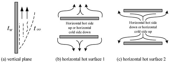
Figure 2.
Schematic diagram of natural convection.

Table 1.
The convection heat dissipation coefficient.
(3) Thermal radiation accounts for a small proportion of the heat transfer of high-frequency transformers, and the amount of radiation heat transfer is related to the temperature and blackness of the material. The calculation formula of the radiation heat transfer of a high-frequency transformer is as follows [19]:
In Equation (12), ε is the emissivity of the radiation heat transfer surface; σ is the Stefan–Boltzmann constant, which is generally taken as 5.67 × 10⁻⁸ W/(m2·K4); A is the Radiation heat transfer area; T1 and T2 represent the average temperature of the radiation heat transfer surfaces 1 and 2, respectively.
2.3. Calculation of the Electromagnetic Force on High-Frequency Transformer Windings
For the electromagnetic force of high-frequency transformer windings, the “field-circuit coupling” theory is generally used for analysis. When performing finite element calculations, the transformer windings are equivalent, and the field-circuit coupling model is shown in Figure 3. Combine the equivalent circuit and the finite element equation to solve the vector magnetic potential A and magnetic flux density B.
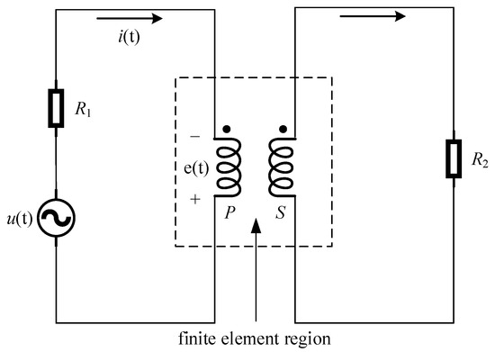
Figure 3.
Circuit-coupled magnetic field model.
According to Figure 3, the circuit equation can be deduced as:
In Equation (13), u(t) is the power supply voltage; i(t) is the winding coil current; e(t) is the winding induced electromotive force; R is the winding resistance; L is the winding inductance.
According to Equation (1), the vector magnetic potential A is introduced, and the induced electromotive force is obtained by integrating the electric field intensity as [16]:
In Equation (14), n is the number of turns; S is the cross-sectional area of the winding; h is the unit vector in the tangential direction of the winding.
Combining Equations (13) and (14), the equivalent circuit equation is obtained:
The magnetic field and the circuit are connected through Equation (15), thereby realizing the field-circuit coupling calculation.
It can be seen from the electromagnetic force calculation formula that the magnitude of the winding electromagnetic force is related to the winding transient current and the spatial leakage magnetic field intensity. The calculation formula of the winding electromagnetic force is [20]:
In Equation (16), V is the volume of the winding coil; J is the current density; B is the leakage magnetic flux density.
In order to facilitate the calculation of the electromagnetic force of the winding, the cylindrical coordinate system is generally used in engineering, and the magnetic leakage flux is divided into axial magnetic leakage flux and radial magnetic leakage flux. The formula is expressed as [21,22]:
In Equation (17), Bφ, Br and Bz are the components of the leakage magnetic flux density; Aφ is the vector magnetic potential.
Correspondingly, the winding electromagnetic force is divided into the axial electromagnetic force Fz and the radial electromagnetic force Fr, expressed as [22,23,24]:
In Equation (18), Fz and Fr are the axial and radial electromagnetic forces of the coil, respectively; Bz and Br are the axial and radial magnetic flux densities, respectively; Jτ is the current density in the tangential direction of the coil.
3. Establishment of the Finite Element Simulation Model of High-Frequency Transformer
3.1. Model Building and Meshing
The high-frequency transformer studied in this article has a shell structure, a rated capacity of 15 kVA, an operating frequency of 5 kHz, and a primary and secondary rated voltage of 760 V. The structural parameters are shown in Table 2.
Table 2.
Structural parameters of HFT.
Based on the structural symmetry and field distribution symmetry of the high-frequency transformer, Magnet electromagnetic field analysis software is used to establish a three-dimensional model of the quarter structure, as shown in Figure 4.
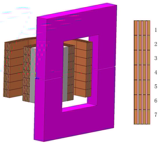
Figure 4.
Simulation model of a high-frequency transformer.
Nanocrystalline magnetic materials have the characteristics of low loss and high magnetic flux density, so high-frequency transformer cores are made of nanocrystalline materials. The iron-core lamination coefficient is 0.78, and the saturation magnetic flux density is 1.2 T. The iron-core structure and its parameters are shown in Figure 5.
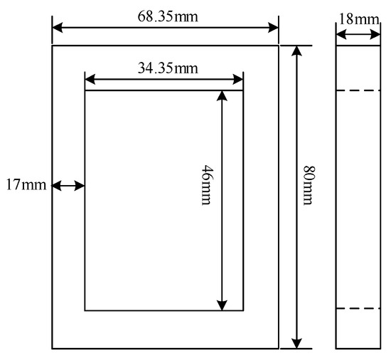
Figure 5.
Schematic diagram of the core structure.
When dividing the finite element model, taking into account the influence of the skin effect and the proximity effect of the copper foil winding at high frequencies, the winding is divided into layers using the layer-by-layer method, and each layer is divided into 0.1 mm within the skin depth; the main body of the iron core. The maximum meshing method is used, the maximum side length of the grid is 2 mm, and the manual meshing tool is used for each side length of the core, which is set to a logarithmic meshing form with a density factor of 3. Air pockets and other structures are meshed using an adaptive mesh with default boundary conditions.
3.2. Material Properties
High-frequency transformers are mainly composed of nanocrystalline iron cores, copper foil windings, insulating paper, epoxy resin and other materials. The magnetic properties of various materials are shown in Table 3. Use Brockhaus measurements to measure the material properties of the nanocrystalline iron core. Place the nanocrystalline magnetic ring on the measurement platform. Wrap two sets of coils on the magnetic ring and connect them to the platform. The magnetization characteristics and loss characteristics of the magnetic ring material are calculated through automatic testing software. The measurement system is shown in Figure 6. When the ambient temperature was measured to be 20 °C, the B–H curve and B–P curve of the nanocrystalline material under non-sinusoidal excitation with a frequency of 5 kHz are shown in Figure 7 and Figure 8, respectively.
Table 3.
Magnetic characteristics of high-frequency transformers materials.
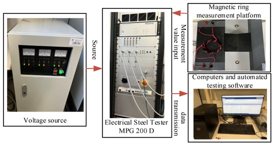
Figure 6.
Nanocrystalline measurement system.
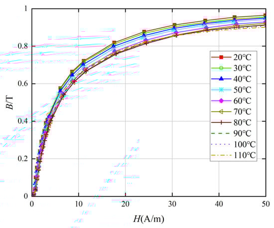
Figure 7.
Magnetization curves of nanocrystalline core within the temperature range from 20 °C to 110 °C.
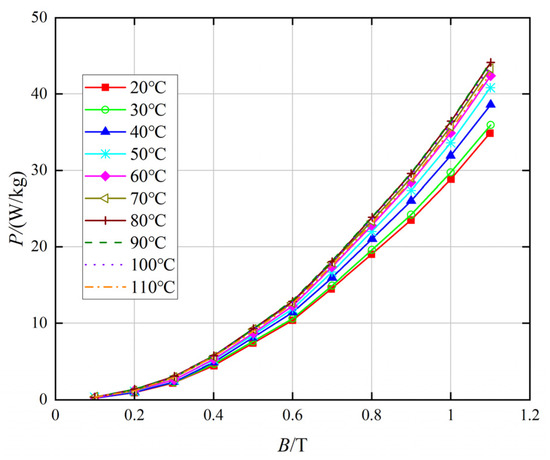
Figure 8.
Loss curves of nanocrystalline core within the temperature range from 20 °C to 110 °C.
Considering the influence of temperature on nanocrystalline materials, the magnetization curve and loss curve of the nanocrystalline iron core at 20~110 °C under 5 kHz non-sinusoidal excitation are measured, as shown in Figure 7 and Figure 8, respectively [13]. Among them, the magnetic permeability of nanocrystalline materials decreases as the temperature increases, and the loss generally shows an upward trend as the temperature increases.
The thermal characteristics of high-frequency transformer materials are shown in Table 4.
Table 4.
Thermal characteristics of high-frequency transformer materials.
3.3. Non-Sinusoidal Excitation Waveforms and Temperature Field Boundary Conditions
The structure of the isolated bidirectional active bridge DC–DC converter based on phase shift control is shown in Figure 9. The duty ratio of the inverter output square wave voltage is 50% [25,26]. MATLAB Simulink is used to build the DAB circuit, and the non-sinusoidal excitation waveform is shown in Figure 10.
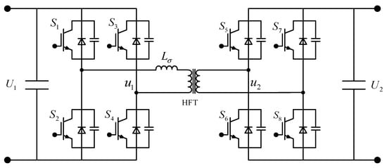
Figure 9.
Schematics of the dual-active-bridge DC–DC converter.
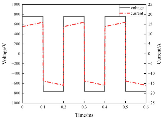
Figure 10.
Non-sinusoidal voltage and current waveforms.
In the temperature field simulation, the ambient temperature is 20 °C, and assuming the steady-state temperature of the transformer is 100 °C, the qualitative temperature is 60 °C. According to the position and size of each convection heat dissipation surface, the convection heat dissipation coefficient according to Table 1 and Formulas (8)–(10) is shown in Table 5.
Table 5.
The convective heat transfer coefficient of a high-frequency transformer.
4. High-Frequency Transformer Multi-Physical Field Simulation
4.1. Magnetic-Thermal Simulation Calculation under No-Load Conditions
The main purpose of the no-load simulation of high-frequency transformers is to compare the changes in core magnetic density, calculate core losses and analyze the temperature field. During simulation, the high-voltage winding of the transformer is open circuited, and non-sinusoidal voltage excitation is applied to the low-voltage winding. MagNet and ThermNet solvers are used to couple the electromagnetic field and temperature field. Set the solution time of the MagNet solver from 0 ms to 0.60 ms with a step size of 0.01 ms; set the solution time of the ThermNet solver from 0 s to 8000 s with a step size of 10 s. Calculate the electromagnetic field and the temperature field of the windings under the conditions of no cross-transposition, partial cross-transposition and complete cross-transposition, respectively. The three winding arrangements are shown in Figure 11 [24,27]. P and S, respectively, represent the single-layer primary winding and secondary winding.
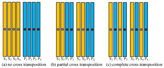
Figure 11.
Winding arrangement of high-frequency transformers.
4.1.1. Core Magnetic Density and Loss under Different Winding Arrangements
The loss of the high-frequency transformer under no-load conditions is mainly iron loss. The core magnetic density and loss are shown in Figure 12. Under the three winding arrangements, the core magnetic flux density is larger at the inner vertex corner and the smallest at the outer vertex corner. Due to the manufacturing process of the iron core, there is an air gap, which results in the maximum magnetic density approaching to the air gap. At 0.60 ms, the core magnetic flux density of the three winding arrangements is the largest. Through comparison, it was found that the core magnetic density when the windings are not cross-transposed is slightly larger than the core magnetic density when the windings are partially cross-transposed and completely cross-transposed. The peak magnetic density of the core with no cross-transposition is approximately 1.130 T, and the peak value of partial cross-transposition and complete cross-transposition is approximately 1.127 T. Although the main magnetic flux in the core decreases slightly after the winding cross-transposition, the overall change is not significant.
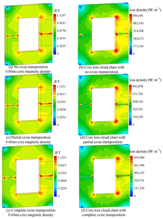
Figure 12.
Distribution of magnetic density and loss fields of core under no-load conditions.
Through observation, it can be seen that the core loss distribution and the magnetic flux density distribution have the same characteristics. In addition, the loss in the core center column is larger because the magnetic flux in this part of the core is the largest, which increases the local eddy current loss accordingly. Through simulation calculation, the core loss is 56.10 W when the windings are not cross-transposed, the core loss is 52.82 W when the windings are partially cross-transposed, and the core loss is 52.48 W when the windings are completely cross-transposed. Winding cross-transposition can reduce core loss during no-load operation, and there is little difference between partial cross-transposition and complete cross-transposition.
4.1.2. Transformer Temperature Rise under Different Winding Arrangements
The steady-state temperature distribution of the high-frequency transformer under no-load conditions is shown in Figure 13. The highest temperature of the transformer is located at the core column. This is because the core loss in this part is large and the core column is enveloped by the low-voltage side winding and insulating medium, which is poor at heat dissipation.
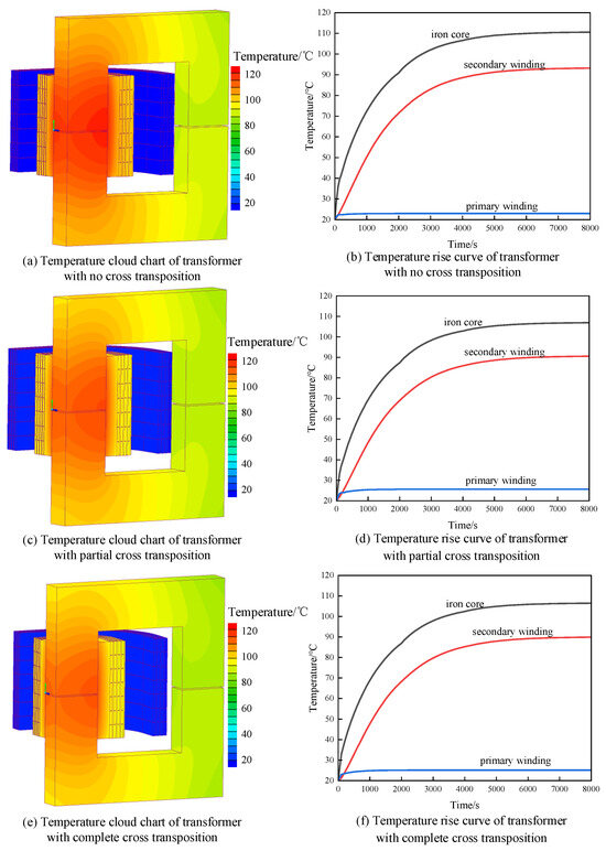
Figure 13.
Temperature of a high-frequency transformer under no-load conditions.
Under the condition of self-heating and convection heat dissipation, the temperature of the no cross-transposition transformer begins to remain stable at approximately 6280 s, with a maximum temperature of 111.6 °C and a minimum temperature of 72.9 °C at the core.
The temperature of the partially cross-transposed transformer begins to remain stable at approximately 5450 s, with a maximum temperature of 107.9 °C and a minimum temperature of 64.1 °C at the core.
The temperature of complete cross-transposed transformer begins to remain stable at approximately 5360 s, with a maximum temperature of 107.4 °C and a minimum temperature of 63.3 °C at the core. Since half of the low-voltage windings are located on the high-voltage side after cross-transposition, their heat is transferred to the high-voltage side windings. Therefore, there is a lower temperature rise on the high-voltage side, and the overall temperature of the transformer is lower than before cross-transposition.
4.2. Magnetic-Thermal Simulation Calculation under Short-Circuit Conditions
The main purpose of high-frequency transformer short-circuit simulation is to calculate winding losses and electromagnetic forces. During simulation, the low-voltage winding is short circuited and the high-voltage winding is excited by non-sinusoidal current. The two-way coupling solution settings of MagNet and ThermNet are the same as those under no-load conditions. The loss generated by the transformer with a short-circuit duration of 0.60 ms is used as the heat source. The overall temperature rise of the transformer is calculated, and the distribution and magnitude of the electromagnetic force in the winding under the short-circuit condition are also solved. The winding arrangement is shown in Figure 11.
4.2.1. Winding Magnetic Density and Loss under Different Winding Arrangements
The winding magnetic density and loss under short-circuit conditions of a high-frequency transformer are shown in Figure 14. When there is no cross-transposition, the leakage magnetic field intensity is larger due to the proximity effect between the primary and secondary windings. After partial cross-transposition, the maximum value of the leakage magnetic field intensity is reduced by 65.24%, and the leakage magnetic field is mainly concentrated between the winding layers. The maximum leakage field intensity after complete cross-transposition is lower than that of partial cross-transposition and the interlayer leakage field intensity is significantly reduced. It can be seen that cross-transposition of windings can effectively reduce magnetic flux leakage.
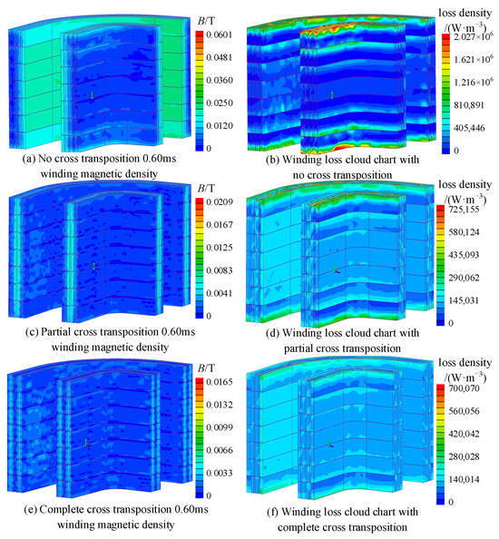
Figure 14.
Distribution of magnetic density and loss fields of windings under short-circuit conditions.
By observing Figure 14, we can see that the loss of the secondary winding is greater than that of the primary winding. When there is no cross-transposition, the loss at both ends of the winding is significantly greater than the loss in the middle. According to the simulation calculation, the loss of the non-cross-transposed winding is 41.60 W, the loss of the partial cross-transposed winding is 32.88 W, and the loss of the complete cross-transposed winding is 30.65 W. After the winding part is cross-transposed, the loss of both ends is significantly reduced, and the overall loss is also significantly reduced. Compared with partial cross-transposition, the loss distribution of complete cross-transposition is more even, and the loss of both ends and overall loss are further reduced.
4.2.2. Transformer Temperature Rise under Different Winding Arrangements
The steady-state temperature distribution of the high-frequency transformer under short-circuit conditions is shown in Figure 15. Since the secondary winding has a large loss and is close to the core, which is not conducive to heat dissipation, its temperature is higher than the overall temperature of the transformer.
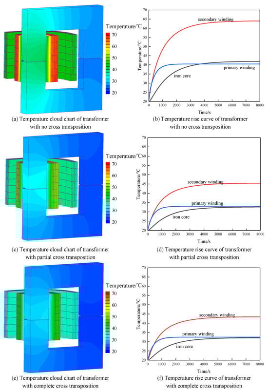
Figure 15.
Temperature of a high-frequency transformer under short-circuit conditions.
When there is no cross-transposition, the stable temperature of the secondary winding is 64.0 °C. The maximum core temperature is 46.8 °C and the minimum core temperature is 27.3 °C.
After the winding part is cross-transposed, the stable temperature of the secondary winding drops to 44.2 °C, and the overall temperature of the transformer drops significantly. The maximum core temperature is 33.5 °C and the minimum core temperature is 23.1 °C. This is because the winding loss is greatly reduced, and the cross-transposition is more conducive to winding heat dissipation.
After complete cross-transposition, the temperature of the secondary winding is reduced to 43.1 °C, which increases the heat dissipation efficiency. The maximum core temperature is 31.6 °C and the minimum core temperature is 22.4 °C.
4.2.3. The Winding Electromagnetic Force under Different Winding Arrangements
According to Equation (16), it can be seen that in order to calculate the electromagnetic force of the winding, it is necessary to clarify the magnitude of the winding current density and the distribution of the spatial leakage magnetic field. The current density and leakage magnetic field distribution under the three winding arrangements are shown in Figure 16.
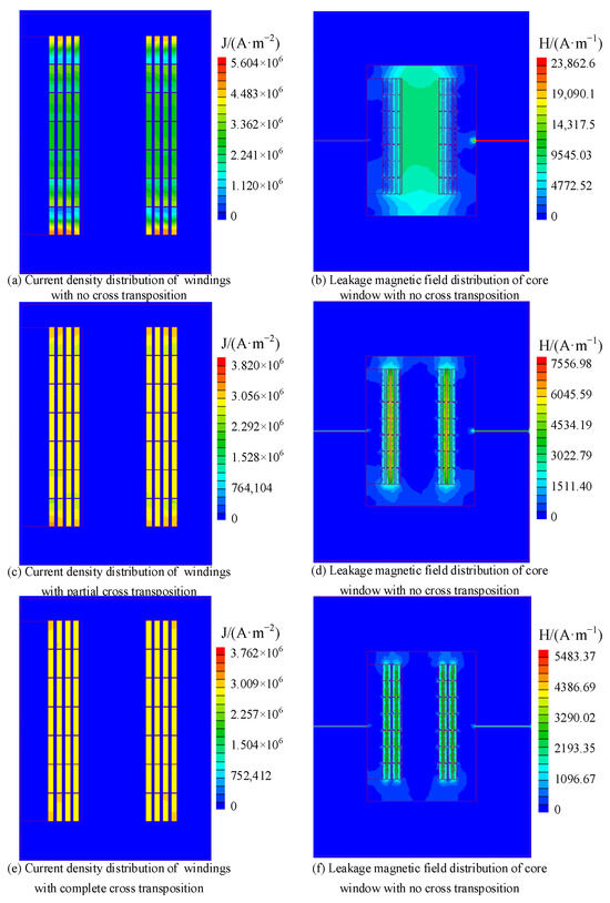
Figure 16.
Current density and leakage magnetic field intensity of windings under short-circuit conditions.
It can be seen from Figure 16 that when there is no cross-transposition, due to the influence of the skin effect and the proximity effect, the maximum current density is located at both ends of the windings of each layer, with a size of 5.60 × 10⁶ A/m2; after partial cross-transposition, the winding skin effect Both the effect and the proximity effect are weakened, and the maximum current density is reduced by 31.78% to 3.82 × 10⁶ A/m2; after using complete cross-transposition, the winding current density is more evenly distributed, and the maximum current density is reduced to 3.76 × 10⁶ A/m2.
It can be seen from Figure 16 that the maximum leakage magnetic field intensity when there is no cross-transposition is 2.38 × 10⁴ A/m, which is located in the air gap of the iron core. The leakage magnetic field mainly exists in the middle area of the primary and secondary windings, the value is 8.80 × 10³ A/m. After using partial cross-transposition, the maximum leakage magnetic field intensity is reduced to 31.66% of that without cross-transposition, the value is 7.55 × 10³ A/m, located between S2, P1 and S4, P3 windings. The leakage magnetic field is mainly concentrated between the winding layers, and its distribution corresponds to the winding magnetic density distribution in (c) of Figure 16. After using complete cross-transposition, the maximum leakage magnetic field intensity is reduced to 5.48 × 10³ A/m, the leakage magnetic field between S2, P1 and S4, P3 winding layers almost disappears, and the leakage magnetic field mainly exists between the remaining winding layers.
Number each layer of windings from top to bottom according to the number of turns, as shown in Figure 4. Based on the electromagnetic field calculation results of the high-frequency transformer under the above three winding arrangements, the field integrator in MagNet is used to extract the volume component of the transient Lorentz force density of each turn coil, and the axial force of each turn coil and maximum radial force.
The axial electromagnetic force distribution curve of each turn coil is shown in Figure 17. It can be seen from the figure: (1) the axial electromagnetic force distribution law corresponds to the current density distribution law shown in Figure 16. The minimum is on the coil in the middle and maximum on the both ends, the winding is in a state of extrusion from both ends to the middle; (2) when there is no cross-transposition, the maximum axial electromagnetic force on the 1st turn and 7th turn of the P3 layer winding is, respectively, −0.00261 N and 0.00278 N; (3) after using partial cross-transposition of windings, the maximum axial electromagnetic force is on the 1st and 7th turns of the P4 winding, and the magnitudes are −7.02 × 10⁻⁴ N and 6.96 × 10⁻⁴ N, respectively, which is 75% less than the maximum value of no cross-transposition; (4) after using complete cross-transposition of windings, the maximum axial electromagnetic force is on the 1st and 7th turns of the P4 winding, which is approximately half of the partial cross-transposition, respectively −3.55 × 10⁻⁴ N and 3.49 × 10⁻⁴ N.
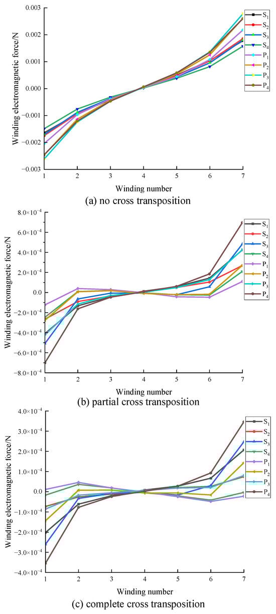
Figure 17.
Winding axial electromagnetic force.
The radial electromagnetic force distribution curve of each turn coil is shown in Figure 18. From the figure, the following conclusions can be drawn: (1) the maximum radial electromagnetic force of each layer of coils is on the middle turn coil, and the radial electromagnetic force is smaller when it is closer to the end of the winding; (2) when there is no cross-transposition, the maximum radial electromagnetic force of the primary and secondary windings is on the adjacent two-layer windings S4 and P1, which is consistent with the leakage magnetic field distribution pattern shown in Figure 18. The maximum radial electromagnetic force is −0.00488 N; (3) after adopting partial cross-transposition, the maximum radial electromagnetic force of the original and secondary sides is on P3 and S4, which are −0.00276 N and 0.00265 N, respectively, which is approximately half of no cross-transposition; the original side winding shrinks inward and the secondary winding expands outward; (4) after adopting complete cross-transposition, the radial electromagnetic force of the original secondary winding is more uniform, and the maximum radial electromagnetic force of the original secondary winding is on P4 and S4. They are −9.08 × 10⁻⁴ N and 8.78 × 10⁻⁴ N, respectively, which are approximately 32.89% of partial cross-transposition.
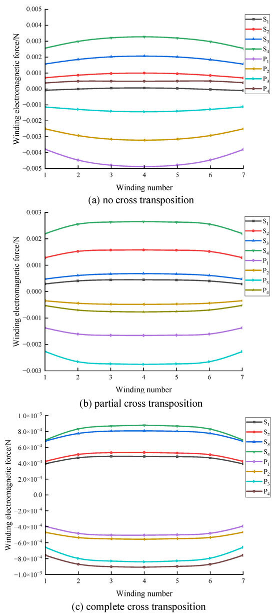
Figure 18.
Winding radical electromagnetic force.
5. Conclusions
In this paper, Brockhaus measuring equipment was used to test the magnetization and loss characteristics of nanocrystalline materials. Based on the nanocrystalline material data at different temperatures, a 15 kV, 5 kHz nanocrystalline high-frequency transformer simulation model was established. The electromagnetic and temperature fields of high-frequency transformers with three different winding arrangements under no-load and short-circuit conditions were calculated and analyzed, respectively. The simulation results in this article show that cross-transposition can reduce core loss because cross-transposition reduces iron loss and is beneficial to transformer heat dissipation, the temperature rise of the transformer is lower than that with no cross-transposition.
For high-frequency transformers under short-circuit conditions, the effect of complete cross-transposition in weakening magnetic leakage is better than that of partial cross-transposition. The complete cross-transposition weakens the overall loss, and the distribution of loss is more even, so the overall temperature of the transformer is lower when windings are completely cross-transposed, and the maximum hot spot temperature rise is 23.1 °C.
Under the short-circuit condition of the high-frequency transformer, the field-circuit coupling analysis method was used to calculate the winding current density and the leakage magnetic field intensity of the core window under three winding arrangements, and the distribution of the winding electromagnetic force was obtained: the axial electromagnetic force causes both ends of the winding to be squeezed toward the middle. The radial electromagnetic force causes the primary winding to shrink inward and the secondary winding to expand outward. Complete cross-transposition can significantly reduce the electromagnetic force on the winding compared with no cross-transposition.
Through the above analysis, it can be seen that the high-frequency transformer winding cross-transposed can reduce the core loss and the temperature rise, and weaken the leakage magnetic flux and deformation of the winding. This research can provide support for the optimal design of high-frequency transformer and multi-physical field simulation and analysis.
Author Contributions
Literature search, B.L. and P.L.; methodology, P.Z.; software, W.L. and B.L.; validation, B.L., P.L. and Z.L.; formal analysis, P.Z.; investigation, W.L.; resources, P.Z. and J.Z.; data curation, B.L. and P.L.; writing—original draft preparation, B.L. and P.Z.; writing—review and editing, P.Z. and J.Z. All authors have read and agreed to the published version of the manuscript.
Funding
This research is supported by the National Natural Science Foundation of China (52007192), Fundamental Research Funds for the Central Universities (2023ZKPYJD09).
Data Availability Statement
Data are contained within this article.
Conflicts of Interest
The authors declare no conflict of interest.
References
- Yu, X.; Su, J.; Lai, J.; Guo, S. Analytical Optimization of Nonsaturated Thermally Limited High-Frequency Transformer/Inductor Design Considering Discreteness of Design Variables. IEEE Trans. Power Electron. 2020, 35, 6231–6250. [Google Scholar] [CrossRef]
- Zhen, T.; Wang, K.; Zheng, Z.; Pang, J.; Li, Y. A review of research on power electronic transformers based on MMC topology. Proc. CSEE 2022, 42, 5630–5649. [Google Scholar]
- Chen, B. Analysis of Effect of Winding Interleaving on Leakage Inductance and Winding Loss of High Frequency Transformers. J. Electr. Eng. Technol. 2019, 14, 1211–1221. [Google Scholar] [CrossRef]
- Zhao, Y.; Wen, T.; Chen, J.; Zhang, Q.; Fu, Z. Characteristics of current distribution under low voltage spiral winding wire transposition structure of power transformer. High Volt. Eng. 2021, 47, 3218–3225. [Google Scholar]
- Zhen, T. Analysis of Electromagnetic Force of Windings in High-Capacity High-Frequency Transformers. Ph.D. Thesis, Shanghai Jiaotong University, Shanghai, China, 2015. [Google Scholar]
- Wang, J.; Zou, Q.; Hu, J.; Fei, W.; Zhao, Y. Optimization design method of a medium-voltage insulated high-power medium-frequency transformer. Trans. China Electrotech. Soc. 2022, 37, 3048–3060. [Google Scholar]
- Zhang, N. Optimization Design Method and Application Research of High Frequency Transformer. Ph.D. Thesis, North China Electric Power University, Beijing, China, 2016. [Google Scholar]
- Zhang, P.; Xiang, X.; Li, W.; Li, B.; Li, L.; Cao, Q. High frequency transformer technology for power electronic transformer. High Volt. Eng. 2022, 48, 4996–5011. [Google Scholar]
- Yin, Y. Loss Calculation, Heat Sink Design and Optimization of High Frequency Transformers. Ph.D. Thesis, North China Electric Power University, Beijing, China, 2017. [Google Scholar]
- Xu, Y.; Li, L.; Yuan, X. Magneto-thermal coupling simulation and experimental verification for a three-winding high-frequency transformer. Int. J. Appl. Electromagn. Mech. 2022, 68, 159–175. [Google Scholar] [CrossRef]
- Sun, C.; Li, L. Calculation and analysis of temperature distribution of high-frequency transformer under non-sinusoidal excitation. High Volt. Appar. 2022, 58, 96–105. [Google Scholar]
- Liu, J.; Lu, Y.; Li, L.; Chen, B. Transient simulation analysis of electromagnetic field and temperature field of high-frequency transformer. High Volt. Eng. 2019, 45, 1191–1200. [Google Scholar]
- Chen, B.; Liang, X.; Wan, N.; Tang, B.; Huang, L. Coupled transient electromagnetic-thermal fields analysis of medium-frequency transformer. High Volt. Eng. 2020, 46, 4400–4409. [Google Scholar]
- Górecki, K.; Detka, K. SPICE-Aided Models of Magnetic Elements—A Critical Review. Energies 2023, 16, 6568. [Google Scholar] [CrossRef]
- Xu, J.; Luo, L.; Li, Y.; Li, J.; Liu, F. Analysis and calculation of windings electromagnetic force of a novel converter transformer. High Volt. Eng. 2007, 33, 102–105. [Google Scholar]
- Wang, K.; Zeng, J.; Zheng, Y.; Lan, S.; Du, G.; Lin, Y. Power transformer based on field-circuit coupling in different operating modes simulation research on leakage magnetic field. J. Harbin Univ. Sci. Technol. 2021, 26, 28–37. [Google Scholar]
- Liang, X. Multiphysics Calculation and Optimal Design of High-Power Medium-Frequency Transformer. Ph.D. Thesis, China Three Gorges University, Hubei, China, 2021. [Google Scholar]
- Zhou, Y.; Guo, J. Optimal Design of Winding Transposition of High-power High-frequency Transformer Applied to HVDC Transmission. In Proceedings of the 2021 4th Asia Conference on Energy and Electrical Engineering (ACEEE), Bangkok, Thailand, 10–12 September 2021; pp. 110–115. [Google Scholar]
- Zhang, X.; Li, G.; Shi, L. Thermal Engineering Foundation, 3rd ed.; China Higher Education Press: Beijing, China, 2008; pp. 174–316. [Google Scholar]
- Ho, S.L.; Li, Y.; Wong, H.C.; Wang, S.H.; Tang, R.Y. Numerical simulation of transient force and eddy current loss in a 720-MVA power transformer. IEEE Trans. Magn. 2004, 40, 687–690. [Google Scholar] [CrossRef]
- Ebrahimi, B.M.; Fereidunian, A.; Saffari, S.; Faiz, J. Analytical estimation of short circuit axial and radial forces on power transformers windings. IET Gener. Transm. Distrib. 2014, 8, 250–260. [Google Scholar] [CrossRef]
- Shang, H.; Zhou, Q.; Ouyang, X.; Dai, J.; Zheng, J. Simulation analysis for partial deformation of transformer winding and distortion of magnetic leakage distribution considering asymmetric mechanical constraint. In Proceedings of the 22nd International Symposium on High Voltage Engineering (ISH 2021), Xi’an, China, 21–26 November 2021; pp. 1083–1088. [Google Scholar]
- Yan, X.; Wang, Z.; Yu, X.; Zhang, Y.; Bai, B.; Xie, D. Research of electromagnetic field for extra-high voltage autotransformer based on magnetic field circuit coupled model. Adv. Technol. Electr. Eng. Energy 2015, 34, 43–47. [Google Scholar]
- Chen, B.; Liang, X.; Qiao, X.; Liu, Z.; Zhang, N.; Zhang, D. Analysis on influence of winding layout on leakage magnetic field and electromagnetic force of high-frequency transformer. High Volt. Appar. 2022, 58, 95–102. [Google Scholar]
- Sha, G.; Wang, C.; Chen, H.; Deng, J.; Wang, J. Unified phasor analytical method for dual-active-bridge DC-DC converter under phase-shift control. Trans. China Electrotech. Soc. 2017, 32, 175–185. [Google Scholar]
- Ataullah, H.; Iqbal, T.; Khalil, I.U.; Ali, U.; Blazek, V.; Prokop, L.; Ullah, N. Analysis of the Dual Active Bridge-Based DC-DC Converter Topologies, High-Frequency Transformer, and Control Techniques. Energies 2022, 15, 8944. [Google Scholar] [CrossRef]
- Wang, B.; Zhang, D.; Tian, Z. CoroTrans-CL: A Novel Transformer-Based Continual Deep Learning Model for Image Recognition of Coronavirus Infections. Electronics 2023, 12, 866. [Google Scholar] [CrossRef]
Disclaimer/Publisher’s Note: The statements, opinions and data contained in all publications are solely those of the individual author(s) and contributor(s) and not of MDPI and/or the editor(s). MDPI and/or the editor(s) disclaim responsibility for any injury to people or property resulting from any ideas, methods, instructions or products referred to in the content. |
© 2023 by the authors. Licensee MDPI, Basel, Switzerland. This article is an open access article distributed under the terms and conditions of the Creative Commons Attribution (CC BY) license (https://creativecommons.org/licenses/by/4.0/).