Article

Miniaturized Dual-Band SIW-Based Bandpass Filters Using Open-Loop Ring Resonators

by
Nrusingha Charan Pradhan
1,
Slawomir Koziel
1,2,*,
Rusan Kumar Barik
1,
Anna Pietrenko-Dabrowska
2 and
Sholampettai Subramanian Karthikeyan
3
1
Engineering Optimization and Modeling Center, Reykjavik University, 102 Reykjavik, Iceland
2
Faculty of Electronics, Telecommunication and Informatics, Gdansk University of Technology, 80-233 Gdansk, Poland
3
Department of Electronics and Communication Engineering, National Institute of Technology, Tiruchirappalli 620015, Tamil Nadu, India
*
Author to whom correspondence should be addressed.
Electronics 2023, 12(18), 3974; https://doi.org/10.3390/electronics12183974
Submission received: 6 September 2023 / Revised: 17 September 2023 / Accepted: 19 September 2023 / Published: 21 September 2023
(This article belongs to the Special Issue Advanced RF, Microwave, and Millimeter-Wave Circuits and Systems)

Abstract

:
This article presents two novel architectures of dual-band substrate-integrated waveguide (SIW) bandpass filters (BPFs). Initially, two identical open-loop ring resonators (OLRRs) were coupled face-to-face on the top of the SIW cavity to realize a dual-band single-pole BPF. To obtain two-pole dual-band characteristics, two OLRRs resonant units were assembled horizontally within the top metal layer of the SIW, which is a technique used for the first time in the literature. For demonstration purposes, two types of SIW filters loaded with OLRRs were designed and fabricated. The proposed filters feature an extremely compact size, a low insertion loss, and good selectivity. The single- and two-pole filters have an overall size of 0.012 λ g 2 and 0.041 λ g 2 , respectively. The simulated and measured circuit responses are in good agreement.

1. Introduction

Conventional rectangular waveguides provide superior performance, great power handling ability, and superior quality factors. As a result, waveguides find applications in many communication systems, including mmWave systems, telemetry systems, and missile radar. However, due to their bulkiness, conventional waveguides are incompatible with planar circuit boards. These issues can be mitigated using substrate-integrated waveguides (SIWs) [1]. SIW structures are formed by two conducting rows placed in a dielectric substrate connecting two parallel metal plate cylinders or holes. The SIW technology is lightweight, cost-efficient, enables high-quality factors, and is simple to deploy on planar structures. SIWs establish a connection between the planar and conventional waveguide technologies [2]. There has been a significant increase in interest in the development of planar low-profile multi-band RF devices, such as filters, couplers, combiners, and more, for modern wireless communication systems. Applying multiple RF devices on a single platform is crucial for meeting the requirements of multiple frequency bands.
In [3], a dual-band BPF utilizing capacitively applied SIW cavities has been presented; however, as the higher-order modes were close to the pass band, the out-of-band rejection was poor, and it was difficult to interface with other devices using a multilayer PCB method. In [4], a perturbed SIW circular cavity was used to develop the BPF. In [5], a miniaturized dual-band BPF has been demonstrated by employing E-shaped slot lines on the SIW cavities’ edge sides. To achieve dual-band bandpass filtering characteristics, two CSRRs were engraved on the top layer of the SIW cavity in [6]. In [7], a dual-band bandpass filter has been developed by employing a single perturbed SIW cavity. A fan-shaped SIW device for dual-band application has been designed in [8]. A dual-band SIW filter has been proposed in [9], which employs a different CSRR on the top of the cavity. In reference [10], a dual-band BPF has been developed using the intrinsic mode approach to achieve a wide frequency ratio. In [11], a BPF has been designed by incorporating two E-shaped slots into the HMSIW cavity. In [12], a Z-shaped slot on an SIW cavity and modified CSRRs were used to demonstrate a BPF. In reference [13], an H-shaped slot has been implemented on the SIW cavity in order to achieve the desired filtering performance.
In reference [14], a three-pole BPF has been designed. The BPF incorporates adjustable transmission zeros and utilizes a dual-mode circular SIW cavity. A triple-mode bandpass filter (BPF) has been designed in [15] using SIW technology. In [16], microwave low-phase noise oscillators have been created using SIW BPF. A perturbating via hole was developed and utilized on the SIW circular cavity to improve the filter’s selectivity. In reference [4], circular SIW cavities were used to design single-band and dual-band bandpass filters. The analysis and implementation of filters using folded circular substrate integrated waveguide cavities (FCSIWCs) have been outlined in [17]. In reference [18], an idea has been made to construct box-like bandpass filters (BPFs) with a wide stopband response by utilizing dual-mode substrate-integrated waveguide cavities. The SIW multilayer technology has been employed to develop a balanced filter in [19]. A modified mode suppression approach was used to implement a broad stopband substrate-integrated waveguide (SIW) filter in [20]. In reference [21], researchers have developed high-order BPFs by applying perturbed SIW cavities. In reference [22], dual-mode miniaturized bandpass filters have been constructed using half-mode substrate-integrated waveguide (HMSIW) cavities. In reference [23], a multilayer method was employed to suppress the higher-order modes of the SIW BPF. The metal layer in the middle section has holes that make it easier to connect rectangular substrate-integrated wave (SIW) resonators on multilayer substrates vertically. This coupling can be achieved through either magnetic or electric coupling. In reference [24], the development of the SIW filter was demonstrated both on and off. The operational frequency range of the filter can be switched between the S-band and the X-band. In [25], a bandpass filter was designed to have a wide upper stopband by using post-loaded SIW resonators. The filter has a wide upper stopband and a lower electric field strength. The SIW coaxial cavity has been utilized for developing narrow-band and wide-band BPFs, as was demonstrated in reference [26]. The investigation and development of QMSIW filters have been stated in an earlier research article [27]. In an investigation presented by researchers [28], a BPF was developed for triple-mode operation. The BPF was loaded with CSRRs and implemented on a SIW square cavity. In a prior research investigation [29], researchers successfully developed a compact bandpass filter (BPF) that exhibited a broad stopband response. This achievement was made possible by combining microstrip and SIW technology. In reference [30], BPFs were designed using HMSIW cavities. In reference [31], researchers developed a BPF that utilizes multilayered substrate-integrated waveguides (SIWs) to achieve a wide upper stopband response. The combination of QMSIW and EMSIW cavities in reference [32] resulted in a compact BPF that exhibits a wide stopband response. In [33], a dual-mode substrate-integrated waveguide (SIW) radial cavity was used to implement a wide-band bandpass filter (BPF). A three-tunable transmission zero was included in the proposed filter in reference [34]. In order to do this, the source and load must use mixed coupling. Cascading two dual-mode cavities constitute an alternate technique for producing extra transmission zeros. The design of a bandpass filter was performed analytically in [25]. The filter should have a reduced electric field intensity and a large upper stopband. Utilizing the post-loaded substrate-integrated waveguide (SIW) resonators’ fundamental mode helped accomplish the goal. An HMSIW cavity has the potential to be used in the construction of compact planar bandpass filters, as was shown by the investigation reported in reference [35]. The fractional bandwidth (FBW) of the fourth-order filters is 31.8%, their footprint size is 0.159 λ g 2 , and they contain one or two transmission zeros. T-septum HMSIW cavities have been used to create third-order bandpass filters, as has been detailed in reference [36]. The filter is highly selective and has a broad stopband and three TZs. A BPW filter has been developed for below 6 GHz applications employing CSRR and SIW technology, as is mentioned in reference [37]. This particular application was the reason for the construction of this filter. The filter offers excellent selectivity, with an FBW of 1.16% and a low insertion loss of 2.9 dB. The work [38] describes an X-band bandpass filter with a dual-mode SIW cavity. Two transmission zeros are included in the filter at 10.75 GHz and 13.3 GHz, which run at a frequency of 12 GHz. This filter has an 11% fractional bandwidth. A multilayer HMSIW resonator bandpass filter was described in the paper [39]. This filter uses a defective microstrip design to provide a broad stopband response. According to the research publication [40], a BPF with two distinct frequency bands can be possibly created by combining a D-shaped ring resonator with a rectangular SIW cavity. This filter is optimized for use at 2.66 and 3.54 GHz frequencies, which are lower than its standard operational frequency of 6 GHz. Reference [41] responded to asymmetric SIW filters. In [42], the development of a bandpass filter utilizing SIW cavities is described. The SIW cavity and interdigital resonators collaborate in this filter to accomplish harmonic suppression. As reference [43] mentioned, a broadband bandpass filter was created using HMSIW cavities. In order to achieve TZs, along with ideal stopband characteristics, this filter employs a multistage stepped impedance resonator.
A BPF has been developed using in-line technology on the HMSIW cavity, as was demonstrated in reference [44]. The filters have the ability to enhance selectivity by utilizing a slot that can generate limited TZs. A BPF has been developed using SIW technology for 5G applications [45]. The CSRRs have been applied to the SIW cavity in order to enhance its filtering performance. A stopband filter has been designed in reference [46]. The insertion loss was achieved at 1.5 dB. Reference [47] describes the development of a BPF capable of operating at two different frequencies. The first band has a resonant frequency of 5 GHz and a bandwidth of 3%. The second band has a resonant frequency of 7.5 GHz and a bandwidth of 4.2%. A tunable BPF utilizing an SIW hexagonal resonator has been reported in [48]. The filter has an insertion loss of 2.01 dB and a FBW of 2.92 percent. A SIW BPF was created by combining two resonators and three inverters, as is explained in reference [49]. Reference [50] extensively addresses conceptualizing and developing a BPF that employs an SIW cavity with iris resonators. The frequency at which the aforementioned filter may function is 9.77 GHz. Its insertion loss is 1.19 decibels, and its fractional bandwidth is 12.17 percent. The work by reference [51] shows how to construct a BPF using an SIW cavity that includes DGS technology in order to obtain complete responses. In the prior work of [52], researchers used an SIW cavity to create a narrow bandpass filter. Inductive posts have been placed on the top surface of this design. The provided filter has a fractional bandwidth of 1.475 percent, as well as an operating frequency of 12.2 GHz. In reference [53], the authors used a cavity in an SIW loaded with cross-shaped slots to successfully construct a dual-mode BPF. When operating at a frequency of 7.5 GHz, the filter has a fractional bandwidth of 9.1 percent. It also has two transmission zeros: one at 12.5 GHz and the other at 15 GHz. According to reference [54], stepped impedance resonators were loaded onto an SIW cavity to develop a compact BPF. The filter has a 4.8 GHz frequency, four TZs, and a FBW of 13%. The footprint of it is 0.3 times the square of the wavelength, which is denoted as λ g 2 . Adopting an SIW cavity filled with a circular patch slot created a dual-mode BPF operating at a frequency of 5.8 GHz [55]. The authors of reference [56] employed a nonresonant mode SIW cavity to develop a BPF. In reference [57], a BPF has been developed using two CSRRs. A third-order BPF has been developed using SIW technology, as is reported in [58].
Notwithstanding, all of the reported circuits exhibit significant insertion loss and a large circuit area. As a matter of fact, the design of SIW-based dual-band bandpass filters of compact size and low insertion loss still poses considerable challenges. In the pursuit of addressing the aforementioned issues, this article proposes a novel architecture of a dual-band SIW-based dual-pole bandpass filter featuring a wide bandpass, low insertion loss, high selectivity, and a compact size. The proposed filters have the highest fractional bandwidth and are the lowest-profile dual-band BPF found in the literature.

2. Filter Design

In the first step of the design process, a traditional SIW rectangular cavity is realized on 0.787-milimeter-thick RT/Duroid 5870 substrate with a dielectric constant of 2.33 and a loss tangent of 0.0012. To obtain a dual-band SIW bandpass filter, open-loop ring resonators (OLRRs) are incorporated on the top conductor of the cavity. Since the electric field is highest in the waveguide center, this design offers a strong coupling between the waveguide and the OLRRs. The resonant frequency of the SIW cavity in the T E m n 0 mode can be calculated as follows [13].
f c ( T E 10 ) = c 2 W s ε r
W s = W d 2 0.95 s
To minimize the energy leakage, the pitch and diameter must be set to d / λ 0 ≤ 0.1 and d / s ≥ 0.5, respectively.

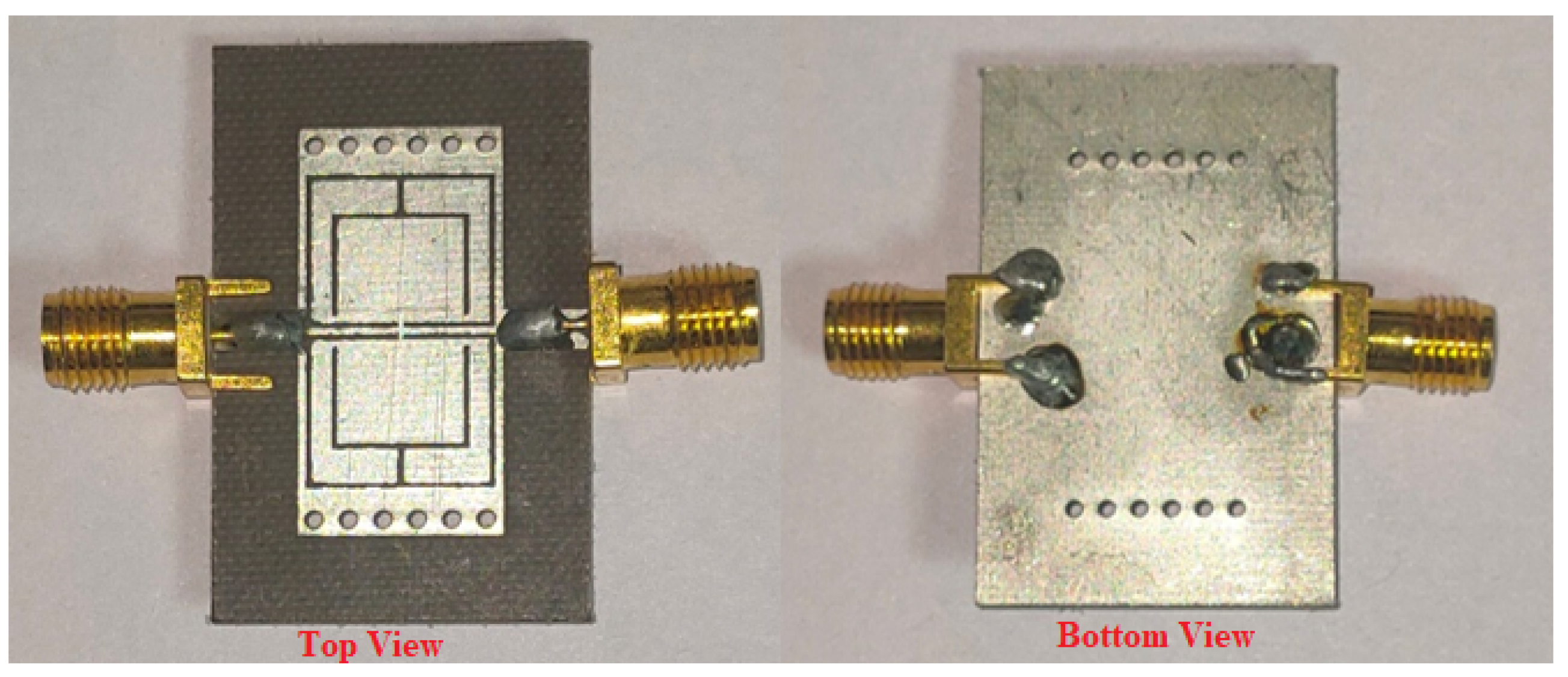
2.1. Dual-Band SIW Filter (Filter I)

Figure 1 shows a proposed SIW-based dual-band bandpass filter. Two identical OLRRs are aligned face-to-face on the top of the SIW cavity to achieve dual-band characteristics. The operating frequencies of the filter are 1.5 GHz and 4.96 GHz, respectively. Due to OLRR loading, the lower passband frequency of the proposed dual-band filter (1.5 GHz) is significantly smaller than the cut-off frequency of the traditional cavity, at 4.46 GHz, which allows us to achieve size reduction. More specifically, the miniaturization rate is 89.2 percent with respect to the traditional cavity. Additionally, two transmission zeros (TZs) are obtained at 3.38 GHz and 7.5 GHz, which ensure good out-of-band rejection.
The circuit model for a dual-band SIW bandpass filter of one cell is shown in Figure 2. The metal vias are modeled as a shunt-connected inductor L w in a linear configuration. L v 1 and C v 1 represent the input coupling that occurs due to electrical and magnetic coupling, respectively. In this approach, the magnetic coupling between the OLRRs and the waveguide transmission line is represented by the vector L v 1 . C v 1 denotes the development of the capacitive coupling between the OLRRs and the waveguide transmission line owing to the slot coupling. The OLRRs are characterized by L u 1 and C u 1 . L v 2 and C v 2 represent the mutual coupling between the OLRRs. The verification of the equivalent circuit model of the dual-band SIW bandpass filter has been carried out using Keysight ADS. The filter circuit parameters have been gathered in Table 1. In addition, the S parameters of the proposed filter have been shown in Figure 3, along with its circuit model and the EM simulation results.
A = 0 1.0019 0 0 1.0019 0.1083 1.2161 0.1065 0 1.2161 0.1518 0.9962 0 0.1065 0.9962 0
B = 0 1.3471 0 0 1.3471 0.1563 1.9340 0.1161 0 1.9340 0.1785 1.3421 0 0.1161 1.3421 0

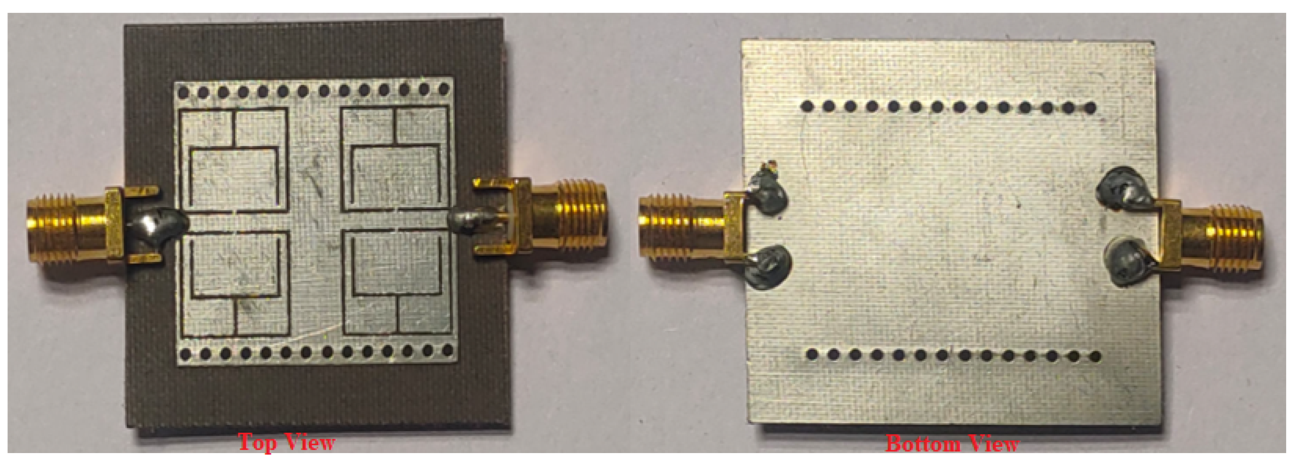
2.2. Two-Pole Dual-Band SIW Filter (Filter II)

Figure 4 shows the architecture of the proposed two-pole dual-band SIW BPF. In the first development step, the dual-band characteristics have been obtained by employing two identical OLRRs (termed as a single resonant unit) on the top of the SIW cavity. Next, two resonant units have been etched horizontally on the top metal layer of the SIW cavity to obtain two-pole dual-band characteristics. The lower passband frequency of the proposed filter is below the cut-off frequency of the traditional SIW cavity, which enables a significant size reduction. The achieved miniaturization rate is 85.3 percent as compared to the traditional SIW cavity. There is a coupling between the two OLRRs. As a result, the OLRRs affect both bands. Therefore, the second band may not be controlled independently and relies on the characteristics of the first band and vice versa. The performance of the proposed two-pole SIW filter is verified using the coupling matrix approach. The ideal coupling matrixes for a lower passband of 1.75 GHz with a TZ at 2.9 GHz and an upper passband of 4.65 GHz with a TZ at 7.12 GHz are shown in (3) and (4), respectively. As demonstrated in Figure 5 and Figure 6, the coupling matrix responses and EM simulation characteristics of the proposed filter are in good agreement. The coupling coefficient k and the loaded quality factor Q 1 are computed by the following [59,60,61] as
k = f p 2 2 f p 1 2 f p 2 2 + f p 1 2
Here, f p 1 and f p 2 represent the lower and upper resonant frequency, respectively.
Q l = f 0 f 3 - dB
where f 0 stands for the resonant frequency, and f 3 - dB is the 3 dB bandwidth.
S 21 = 20 l o g 10 Q l Q e
1 Q l = 1 Q u + 1 Q e
Figure 7 shows the variability of the coupling coefficient with respect to the horizontal separation K 2 and vertical separation K 3 of the OLRRs. The graph indicates that the coupling coefficient is inversely proportional to K 2 , whereas it is directly proportional to K 3 . Thus, the coupling coefficient k can be controlled by the parameters K 2 and K 3 . The passband bandwidth can be adjusted by changing the position of the OLRRs. The distance between two OLRRs, specifically K 3 , can be altered, thereby resulting in the ability to control the bandwidth. The electric field distributions of a one-cell and two-pole dual-band SIW bandpass filter are shown in Figure 8 and Figure 9. The proposed BPF has three types of losses: radiation loss, conductor loss, and dielectric loss. The radiation loss occurs because of the electromagnetic power leakage in the space between adjacent vias within the SIW cavity. Conductor loss occurs due to the metallic vias embedded in the substrate and the finite conductivity of the metal plates from top to bottom. Dielectric loss is caused by the dielectric material’s loss tangent ( tan δ ). However, the main factor contributing to the losses in the BPF is primarily radiation loss, while other forms of loss have a minimal impact.
For the two-pole dual-band BPF structure, the theoretical external quality factors Q e of the two passbands are calculated as Q e I = 5.83 and Q e I I = 10.82. Similarly, the unloaded quality factors Q u of the two passbands can be calculated as Q u I = 53.7 and Q u I I = 151.7.
Based on the above study, the following simple design rules are recommended:
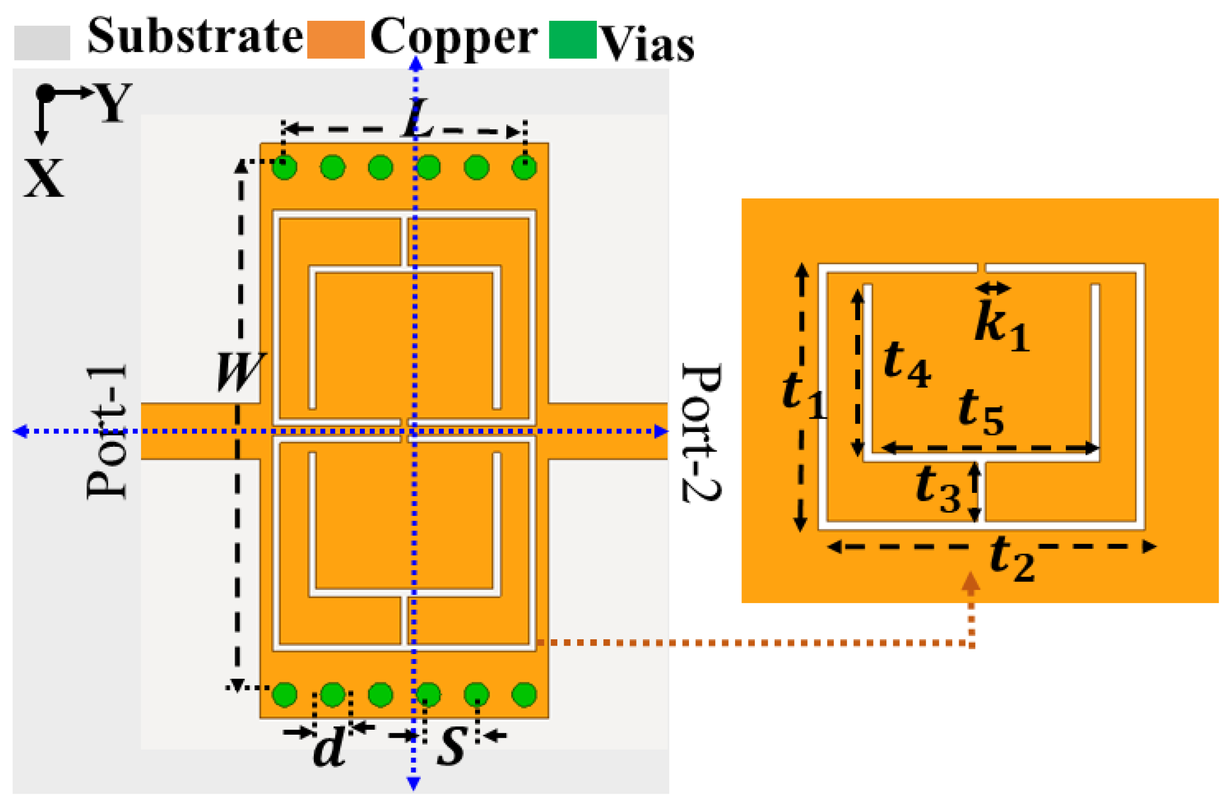
  • In the first step, design an SIW cavity with the dimensions of 0.08 λ g for L and 0.012 λ g for W;
  • Observe the filtering response of the single cavity with no load applied to the top of the cavity;
  • Next, to realize a dual-band single-pole BPF, implement two identical open-loop ring resonators (OLRRs) in a face-to-face arrangement on the top of the SIW cavity;
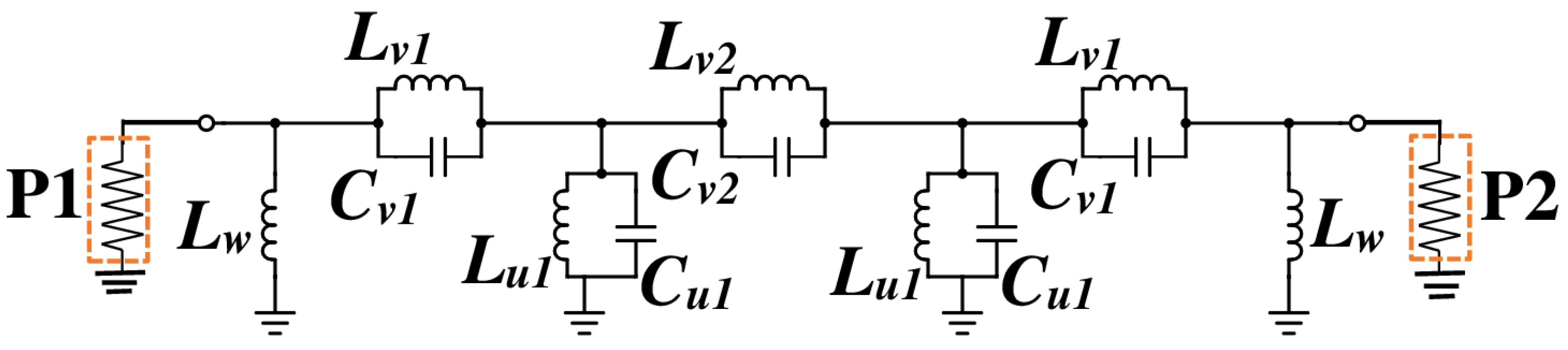
  • Develop the equivalent circuit model for a single-pole dual-band BPF by considering all the physical parameters of the BPF;
  • Next, design another SIW cavity with the dimensions of 0.22 λ g for L and 0.019 λ g for W;
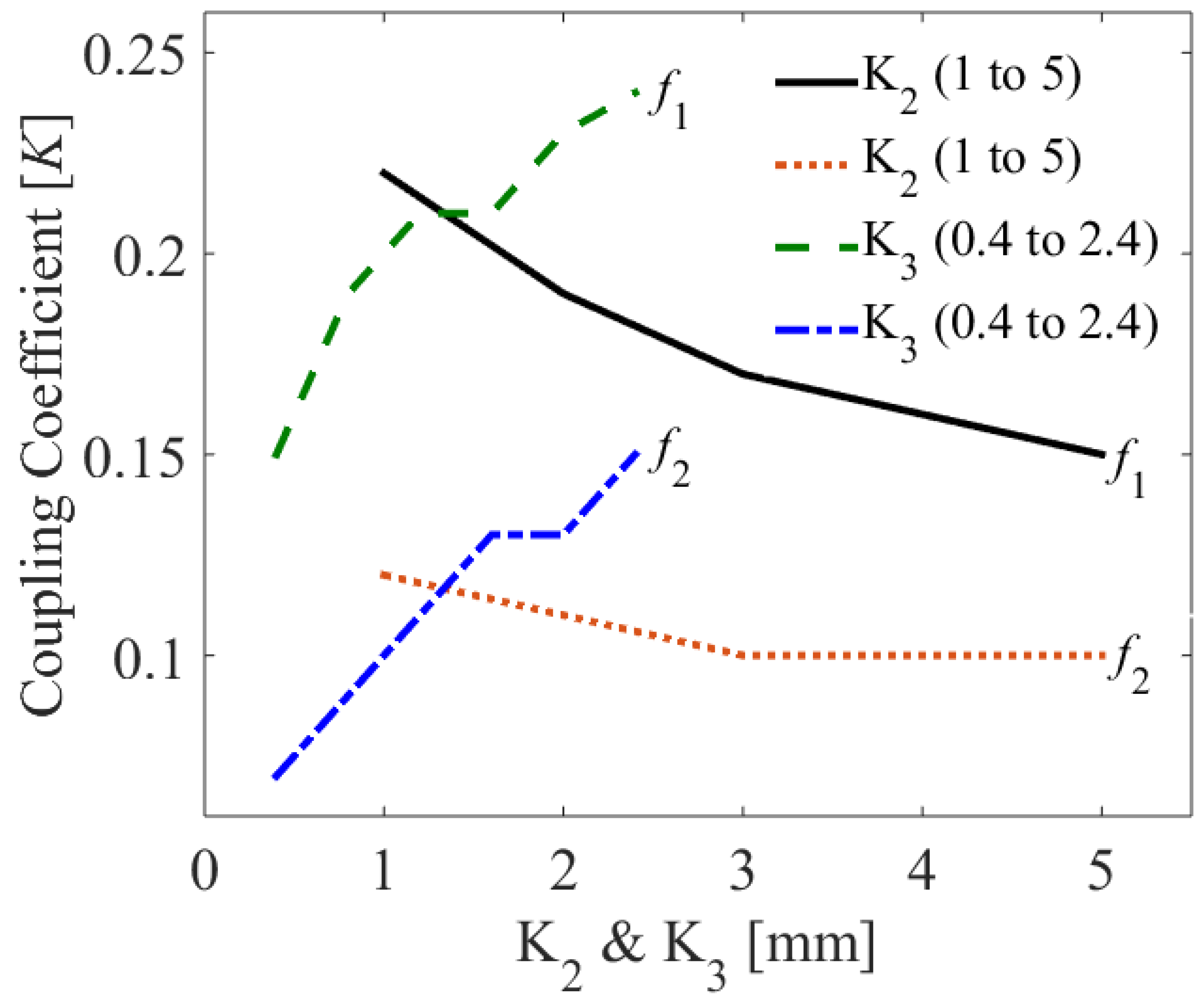
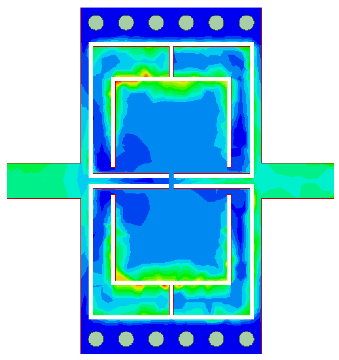
  • To obtain two-pole dual band characteristics, assemble two OLRR resonant units horizontally within the top metal layer of SIW cavity;
  • To achieve the desired filtering response, optimize k 2 and k 3 .

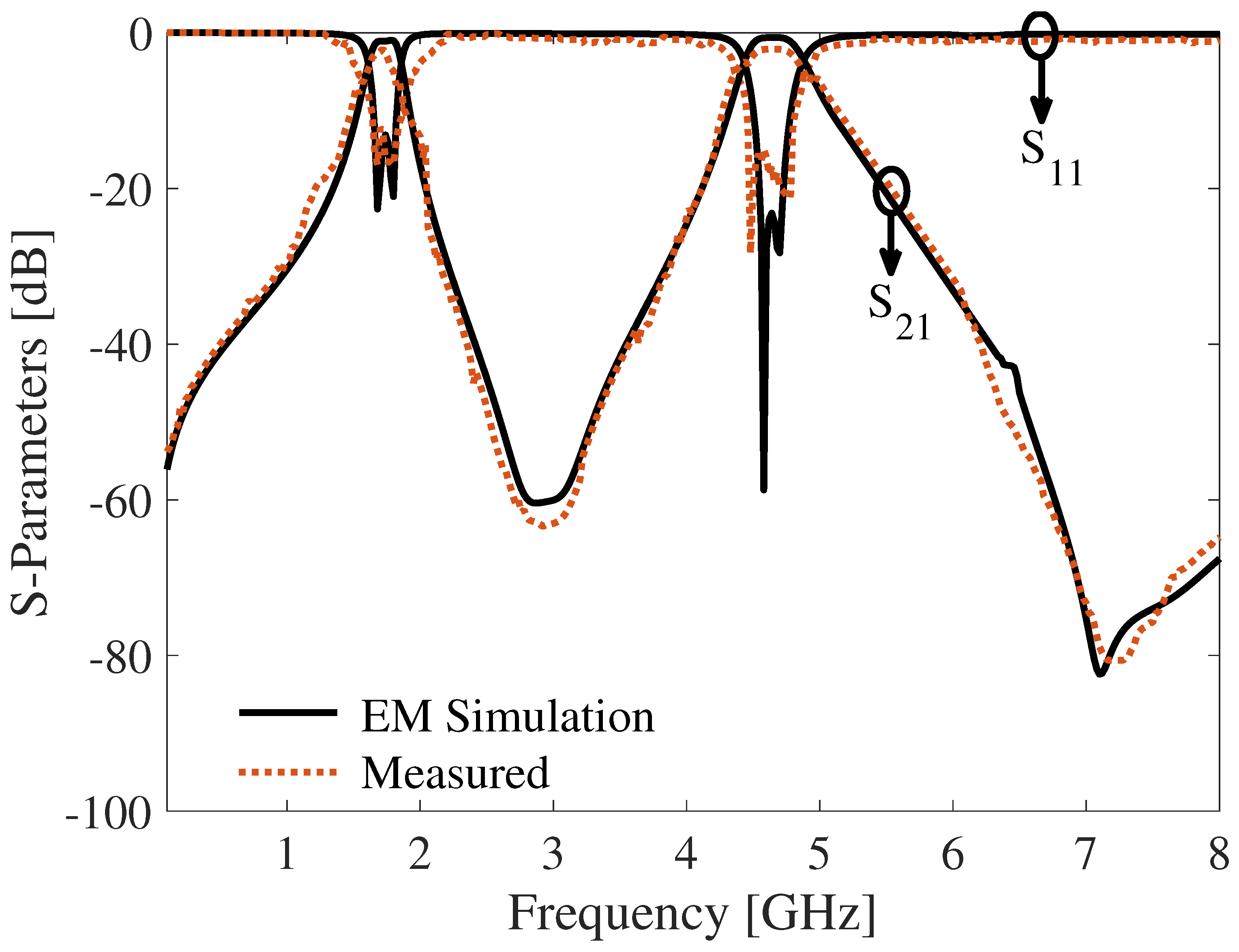
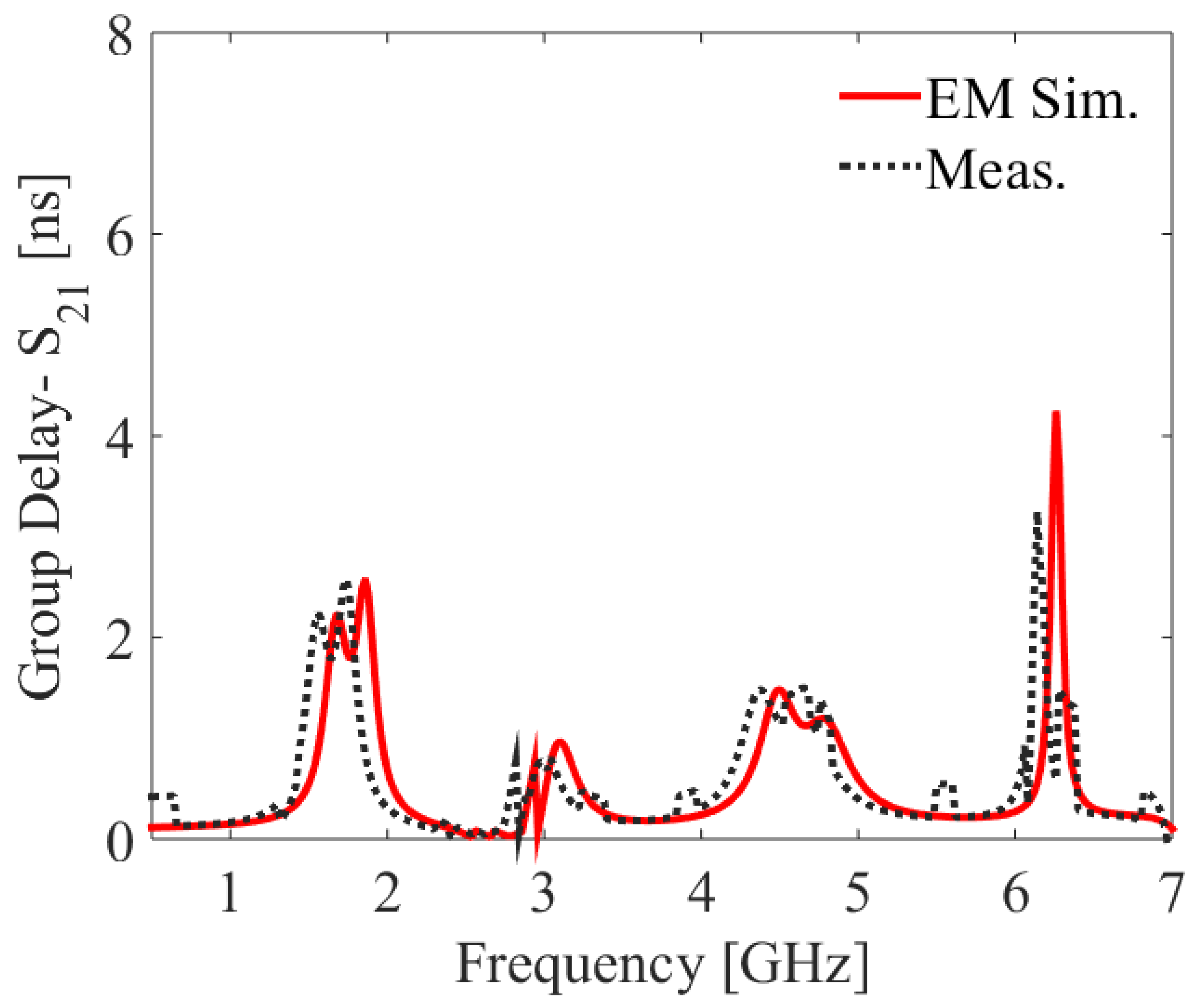
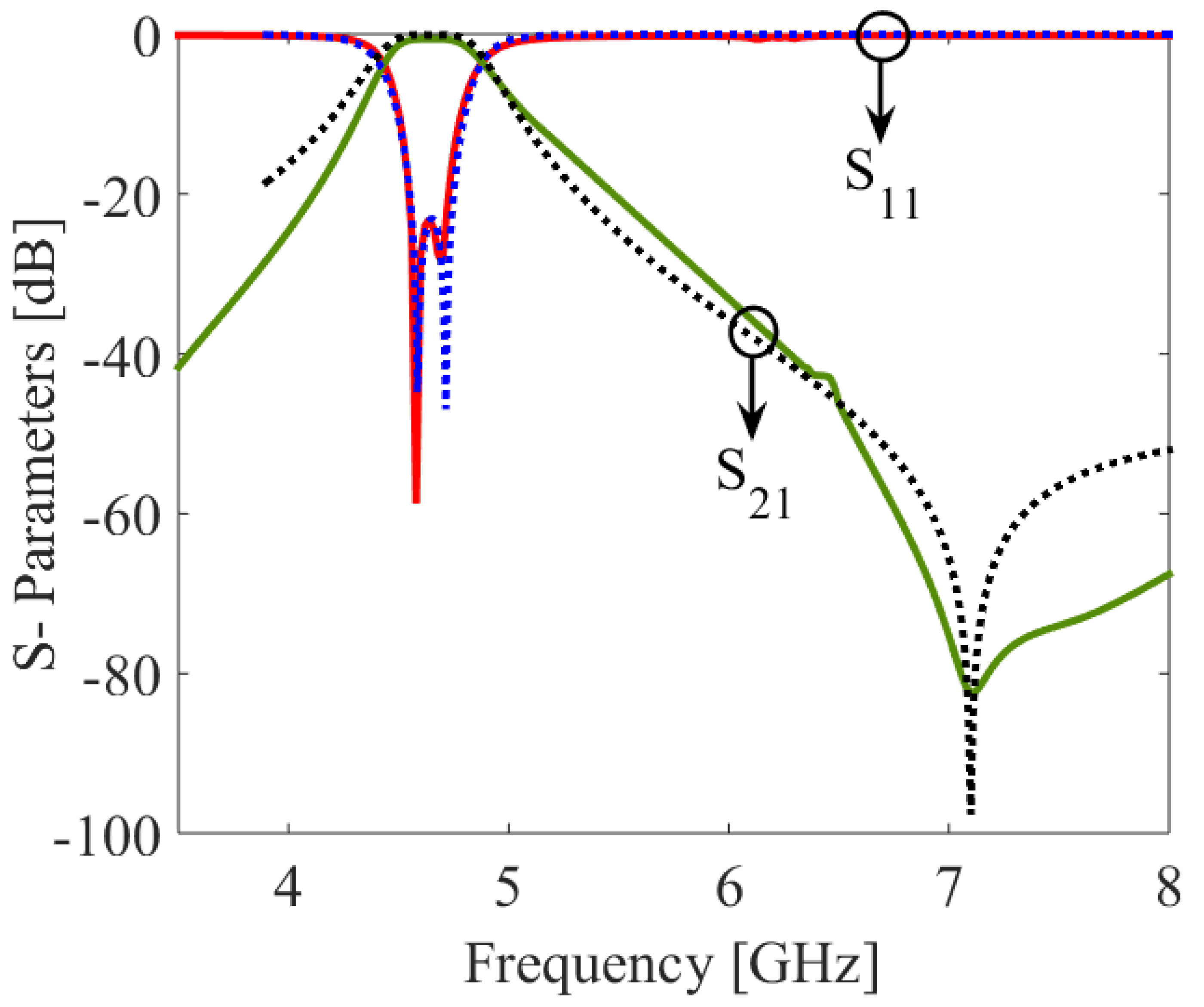
3. Experimental Validation

In order to verify the suggested structure, two prototypes of dual-band SIW BPFs (dual-narrowband and dual-wideband) were fabricated and experimentally tested. Figure 10 depicts photographs of the SIW-based BPF prototype for a one-cell, dual-band SIW BPF. Figure 11 displays photographs of the prototype SIW-based BPF for a two-cell dual-band SIW BPF. The overall sizes of the single-cell and two-pole dual-band SIW BPFs are 0.012 λ g 2 and 0.041 λ g 2 , respectively. The R&S network analyzer has been used to measure the circuit characteristics.
A comparison of the EM-simulated and tested transmission responses of the dual-narrowband SIW filter has been shown in Figure 12. The lower and upper passbands were centered at 1.5 GHz and 4.96 GHz, respectively. The in-band return loss was determined to be better than 20 dB for both bands. The insertion loss in the lower passband was found to be 0.85 dB, while it was 0.9 dB in the upper passband. According to the measured data, the 3 dB fractional bandwidths (FBWs) were 14% and 7.3% at the lower and upper passbands, respectively. Two TZs were realized at 3.38 GHz and 7.5 GHz. The stop-band rejection of this filter was fairly good, since the evanescent waves propagated below the waveguide cut-off frequency.
The EM-simulated and tested results for a two-pole dual-band SIW filter have been shown in Figure 13. The two passbands were located at 1.75 GHz and 4.65 GHz, respectively. It has been observed that the return loss was better than 14 dB on both of the operating bands. The insertion loss for the lower passband was recorded as 1.1 dB, while the upper passband was recorded as 1.15 dB. The 3 dB FWBs were obtained as 14.9% and 10.4%, respectively. From the measured data, it was found that the TZs were located at 2.9 GHz and 7.12 GHz, respectively. Both the simulation and measurement data indicate that the two passbands were followed by the respective TZs, which significantly improved the circuit selectivity and out-of-band rejection. The group delay response of the proposed two-pole dual-band SIW filter was computed as shown in Figure 14. The proposed bandpass filters are suitable for a range of applications, including L-band, INSAT C-band, 5G, and satellite. However, the dimensions of the OLRRs and the SIW cavities may be optimized to meet the specifications for a wide range of applications.
The comparative analysis provided in Table 2 allows us to summarize the essential performance features of the proposed SIW-based dual-band bandpass filters:
  • The dual-band SIW filters exhibit smaller size than the designs reported in the literature [4,5,6,7,8,9,10,11,12];
  • Unlike the proposed filters, the majority of the benchmark circuits [8] exhibited significant insertion loss;
  • In comparison to [4,5,6,7,8,9,10,11,12], the fractional bandwidth of the proposed filters was much higher than that reported for the benchmark structures.

4. Conclusions

This paper proposed novel architectures of miniaturized SIW dual-band bandpass filters. The underlying concept was to produce two operating passbands that were well below the cutoff frequency of the waveguide. This was achieved by carefully configuring the OLRRs employed as the fundamental building blocks of the circuit. The proposed circuits exhibited attractive features such as low cost, simple integration capabilities, and low insertion loss, which were all validated experimentally. Owing to their small size, the proposed filters are particularly suitable for low frequency applications.

Author Contributions

Conceptualization, N.C.P. methodology, N.C.P. and S.K.; software, N.C.P., R.K.B. and S.K.; validation, A.P.-D. and S.K.; formal analysis, N.C.P. and A.P.-D.; investigation, R.K.B. and A.P.-D.; resources, S.K.; data curation, N.C.P., S.S.K. and S.K.; writing original draft preparation, N.C.P., S.S.K. and A.P.-D.; writing—review and editing, N.C.P. and S.K.; visualization, N.C.P., R.K.B. and S.K.; supervision, S.K.; project administration, S.K.; funding acquisition, A.P.-D. All authors have read and agreed to the published version of the manuscript.

Funding

This work was supported in part by the Icelandic Centre for Research (RANNIS), grant 217771, and by the National Science Centre of Poland grants 2020/37/B/ST7/01448.

Data Availability Statement

Not applicable.

Acknowledgments

The authors would like to thank Dassault Systemes, France, for making the CST Microwave Studio available.

Conflicts of Interest

The authors declare no conflict of interest.

References

  1. Bozzi, M.; Georgiadis, A.; Wu, K. Review of substrate-integrated waveguide circuits and antennas. IET Microw. Ant. Propag. 2011, 5, 909–920. [Google Scholar] [CrossRef]
  2. Dong, Y.D.; Yang, T.; Itoh, T. Substrate integrated waveguide loaded by complementary split-ring resonators and its applications to miniaturized waveguide filters. IEEE Trans. Microw. Theory Tech. 2009, 57, 2211–2223. [Google Scholar] [CrossRef]
  3. Li, M.; Chen, C.; Chen, W. Miniaturized dual-band filter using dual-capacitively loaded SIW cavities. IEEE Microw. Wirel. Compon. Lett. 2017, 27, 344–346. [Google Scholar] [CrossRef]
  4. Azad, A.R.; Mohan, A. Single-and dual-band bandpass filters using a single perturbed SIW circular cavity. IEEE Microw. Wirel. Compon. Lett. 2019, 29, 201–203. [Google Scholar] [CrossRef]
  5. Zhang, H.; Kang, W.; Wu, W. Miniaturized dual-band SIW filters using E-shaped slotlines with controllable center frequencies. IEEE Microw. Wirel. Compon. Lett. 2018, 28, 311–313. [Google Scholar] [CrossRef]
  6. Zhang, H.; Kang, W.; Wu, W. Dual-band substrate integrated waveguide bandpass filter utilising comple-mentary split-ring resonators. Electron. Lett. 2018, 54, 85–87. [Google Scholar] [CrossRef]
  7. Li, M.; Chen, C.; Chen, W.; Zhang, H. A novel dual-band bandpass filter using a single perturbed substrate integrated waveguide cavity. In Proceedings of the 2017 IEEE MTT-S International Microwave Symposium (IMS), Honolulu, HI, USA, 4–9 June 2017; pp. 1076–1079. [Google Scholar]
  8. Zhang, S.; Rao, J.Y.; Hong, J.S.; Liu, F.L. A novel dual-band controllable bandpass filter based on fan-shaped substrate integrated waveguide. IEEE Microw. Wirel. Compon. Lett. 2018, 28, 308–310. [Google Scholar] [CrossRef]
  9. Shen, W.; Yin, W.Y.; Sun, X.W. Miniaturized dual-band substrate integrated waveguide filter with control-lable bandwidths. IEEE Microw. Wirel. Compon. Lett. 2011, 21, 418–420. [Google Scholar] [CrossRef]
  10. Xie, H.W.; Zhou, K.; Zhou, C.X.; Wu, W. Compact SIW diplexers and dual-band bandpass filter with wide-stopband performances. IEEE Trans. Circuits Syst. II Express Briefs 2020, 67, 2933–2937. [Google Scholar] [CrossRef]
  11. Iqbal, A.; Tiang, J.J.; Lee, C.K.; Mallat, N.K.; Wong, S.W. Dual-band half mode substrate integrated wave-guide filter with independently tunable bands. IEEE Trans. Circuits Syst. II Express Briefs 2019, 67, 285–289. [Google Scholar]
  12. Yin, B.; Lin, Z. A novel dual-band bandpass SIW filter loaded with modified dual-CSRRs and Z-shaped slot. AEU-Int. J. Electron. Commun. 2020, 121, 153261. [Google Scholar] [CrossRef]
  13. Iqbal, A.; Ahmad, A.W.; Smida, A.; Mallat, N.K. Tunable SIW bandpass filters with improved upper stopband performance. IEEE Trans. Circuits Syst. II Express Briefs 2019, 67, 1194–1198. [Google Scholar] [CrossRef]
  14. Cheng, F.; Lin, X.Q.; Lancaster, M.; Song, K.; Fan, Y. A dual-mode substrate integrated waveguide filter with controllable transmission zeros. IEEE Microw. Wirel. Compon. Lett. 2015, 25, 576–578. [Google Scholar] [CrossRef]
  15. Liu, Q.; Zhou, D.; Shi, J.; Hu, T. High-selective triple-mode SIW bandpass filter using higher-order resonant modes. Electron. Lett. 2020, 56, 37–39. [Google Scholar] [CrossRef]
  16. Duong, T.V.; Hong, W.; Tran, V.H.; Vu, T.A.; Huang, W.C.; Choubey, P.N. An Alternative Technique to Minimize the Phase Noise of X-band Oscillators Using Improved Group Delay SIW Filters. IEEE Microw. Wirel. Compon. Lett. 2017, 27, 153–155. [Google Scholar] [CrossRef]
  17. Zhu, F.; Wu, Y.; Zhao, X.; Chu, P.; Luo, G.Q.; Wu, K. Stopband Bandpass Filters Based on Dual-Mode Folded Circular Substrate IntegratedWaveguide Cavities. IEEE Trans. Microw. Theory Tech. 2023. early access. [Google Scholar]
  18. Liu, Q.; Zhang, D.; Tang, M.; Deng, H.; Zhou, D. A Class of Box-Like Bandpass Filters With Wide Stopband Based on New Dual-Mode Rectangular SIW Cavities. IEEE Trans. Microw. Theory Tech. 2021, 69, 101–110. [Google Scholar] [CrossRef]
  19. Deng, H.W.; Han, Y.K.; Sun, L.; Zhu, J.M.; Xing, S.B. Multilayer dualmode balanced SIW filter utilizing PEC-PMC characteristic for commonmode suppression. IEEE Microw. Wirel. Compon. Lett. 2020, 30, 865–868. [Google Scholar] [CrossRef]
  20. Xie, H.W.; Zhou, K.; Zhou, C.X.; Wu, W. Wide-stopband SIW filters using modified multi-spurious modes suppression technique. IEEE Trans. Circuits Syst. II Exp. Briefs 2020, 67, 2883–2887. [Google Scholar] [CrossRef]
  21. Zhu, F.; Luo, G.Q.; You, B.; Zhang, X.H.; Wu, K. Planar dual-mode bandpass filters using perturbed sub-strate-integrated waveguide rectangular cavities. IEEE Trans. Microw. Theory Tech. 2021, 69, 3048–3057. [Google Scholar] [CrossRef]
  22. Zhu, F.; Luo, G.Q.; Liao, Z.; Dai, X.W.; Wu, K. Compact dual-mode bandpass filters based on half-mode substrate-integrated waveguide cavities. IEEE Microw. Wirel. Compon. Lett. 2021, 31, 441–444. [Google Scholar] [CrossRef]
  23. Jia, D.; Feng, Q.; Xiang, Q.; Wu, K. Multilayer substrate integrated waveguide (SIW) filters with higher-order mode suppression. IEEE Microw. Wirel. Compon. Lett. 2016, 26, 678–680. [Google Scholar] [CrossRef]
  24. Lee, B.; Nam, S.; Lee, T.H.; Ahn, C.S.; Lee, J. Single-filter structure with tunable operating frequency in noncontiguous bands. IEEE Trans. Compon. Packag. Manuf. Technol. 2016, 7, 98–105. [Google Scholar] [CrossRef]
  25. Lee, B.; Nam, S.; Jeong, S.W.; Lee, J. Post-loaded substrate-integrated waveguide bandpass filter with wide upper stopband and reduced electric field intensity. IEEE Microw. Wirel. Compon. Lett. 2020, 30, 371–374. [Google Scholar] [CrossRef]
  26. Sanchez-Soriano, M.A.; Sirci, S.; Martinez, J.D.; Boria, V.E. Compact dual-mode substrate integrated waveguide coaxial cavity for bandpass filter design. IEEE Microw. Wirel. Compon. Lett. 2016, 26, 386–388. [Google Scholar] [CrossRef]
  27. Moscato, S.; Tomassoni, C.; Bozzi, M.; Perregrini, L. Quarter-mode cavity filters in substrate integrated waveguide technology. IEEE Trans. Microw. Theory Tech. 2016, 64, 2538–2547. [Google Scholar] [CrossRef]
  28. Liu, Z.; Xiao, G.; Zhu, L. Triple-mode bandpass filters on CSRR-loaded substrate integrated waveguide cavities. IEEE Trans. Compon. Pack. Manuf. Technol. 2016, 6, 1099–1105. [Google Scholar] [CrossRef]
  29. Zhu, Y.; Dong, Y. A novel compact wide-stopband filter with hybrid structure by combining SIW and mi-crostrip technologies. IEEE Microw. Wirel. Compon. Lett. 2021, 31, 841–844. [Google Scholar] [CrossRef]
  30. Weng, M.H.; Tsai, C.Y.; Chen, D.L.; Chung, Y.C.; Yang, R.Y. A bandpass filter using half mode SIW structure with step impedance resonator. Electronics 2020, 10, 51. [Google Scholar] [CrossRef]
  31. Bayati, M.S.; Khorand, T. Compact SIW directional filter using substrate integrated circular cavities. Int. J. Microw. Wirel. Technol. 2020, 12, 352–355. [Google Scholar] [CrossRef]
  32. Kim, P.; Jeong, Y. Compact and wide stopband substrate integrated waveguide bandpass filter using mixed quarter-and one-eighth modes cavities. IEEE Microw. Wirel. Compon. Lett. 2019, 30, 16–19. [Google Scholar] [CrossRef]
  33. Liu, Q.; Zhou, D.; Wang, S.; Zhang, Y. Highly-selective pseudoelliptic filters based on dual-mode substrate integrated waveguide resonators. Electron. Lett. 2016, 52, 1233–1235. [Google Scholar] [CrossRef]
  34. Xu, Z.; Shi, Y.; Xu, C.; Wang, P. A novel dual mode substrate integrated waveguide filter with mixed source-load coupling (MSLC). Prog. Electromagn. Res. 2013, 136, 595–606. [Google Scholar] [CrossRef]
  35. Liu, D.; Dong, Y. Compact Low-Loss Half-Mode Substrate Integrated Waveguide Filter with Controllable Transmission Zeros. IEEE Trans. Circuits Sys. II Exp. Briefs 2022, 69, 4248–4252. [Google Scholar] [CrossRef]
  36. Chen, K.F.; Yang, X.; Zhou, L.; Mao, J.F. Miniaturized half-mode T-septum SIW bandpass filter with an ultrawide stopband. IEEE Microw. Wireless Compon. Lett. 2021, 31, 853–856. [Google Scholar] [CrossRef]
  37. Praveena, N.; Gunavathi, N. High Selectivity SIW Cavity Bandpass Filter Loaded CSRR with Perturbing Vias for Sub-6 GHz Applications. Progress Electrom. Res. Lett. 2023, 109, 103–110. [Google Scholar] [CrossRef]
  38. Qin, P.Y.; Liang, C.H.; Wu, B.; Su, T. Novel dual-mode bandpass filter with transmission zeros using substrate integrated waveguide cavity. J. Electromagn. Waves Appl. 2008, 22, 723–730. [Google Scholar] [CrossRef]
  39. You, B.; Chen, L.; Luo, G. The novel reconfigurable double-layer half-mode SIW filter with tunable DMS structure. J. Electromagn. Waves Appl. 2018, 32, 1816–1823. [Google Scholar] [CrossRef]
  40. Tharani, D.; Barik, R.K.; Cheng, Q.S.; Selvajyothi, K.; Karthikeyan, S.S. Compact dual-band SIW filters loaded with double ring D-shaped resonators for sub-6 GHz applications. J. Electromagn. Waves Appl. 2021, 35, 923–936. [Google Scholar] [CrossRef]
  41. Li, R.; Du, G. A SIW filter with asymmetric frequency response by non-resonating node. J. Electromagn. Waves Appl. 2013, 27, 1550–1556. [Google Scholar] [CrossRef]
  42. Kurudere, S.; Ertürk, V.B. SIW-based interdigital bandpass filter with harmonic suppression. Microw. Opt. Technol. Lett. 2015, 57, 66–96. [Google Scholar] [CrossRef]
  43. Li, D.; Yu, Y.; Tang, M.C.; Shi, T. Design of compact wideband bandpass filter with broad stopband using hybrid HMSIW and open-circuit tri-section stepped impedance resonators. Microw. Opt. Technol. Lett. 2018, 60, 2998–3003. [Google Scholar] [CrossRef]
  44. Pelluri, S.; Mv, K. A narrow band and high selectivity half-mode substrate integrated waveguide bandpass filter with interdigital slots. Microw. Opt. Technol. Lett. 2021, 63, 1180–1186. [Google Scholar] [CrossRef]
  45. Tharani, D.; Barik, R.K.; Cheng, Q.S.; Selvajyothi, K.; Karthikeyan, S.S. Miniaturized SIW filter using D-shaped resonators with wide out-of-band rejection for 5G applications. J. Electromagn. Waves Appl. 2020, 34, 2397–2409. [Google Scholar]
  46. Che, W.; Li, C.; Deng, K.; Yang, L. A novel bandpass filter based on complementary split rings resonators and substrate integrated waveguide. Microw. Opt. Technol. Lett. 2008, 50, 699–701. [Google Scholar] [CrossRef]
  47. Liu, C.; An, X. A SIW-DGS wideband bandpass filter with a sharp roll-off at upper stopband. Microw. Opt. Technol. Lett. 2017, 59, 789–792. [Google Scholar] [CrossRef]
  48. Zhao, Q.; Chen, Z.; Huang, J.; Li, G.; Zhang, Z.; Dang, W. Compact dual-band bandpass filter based on composite right/left-handed substrate integrated waveguide loaded by complementary split-ring resonators defected ground structure. J. Electromagn. Waves Appl. 2014, 28, 1807–1814. [Google Scholar] [CrossRef]
  49. Xu, Z.Q.; Shi, Y.; Wang, P.; Liao, J.X.; Wei, X.B. Substrate integrated waveguide (SIW) filter with hexagonal resonator. J. Electromagn. Waves Appl. 2012, 26, 1521–1527. [Google Scholar] [CrossRef]
  50. Alhzzoury, A.I.; Raveu, N.; Prigent, G.; Pigaglio, O.; Baudrand, H.; Al-Abdullah, K. Substrate integrated waveguide filter design with wave concept iterative procedure. Microw. Opt. Technol. Lett. 2011, 53, 2939–2942. [Google Scholar] [CrossRef]
  51. Rhbanou, A.; Bri, S.; Sabbane, M. Design of X-band substrate integrated waveguide bandpass filter with dual high rejection. Microw. Opt. Technol. Lett. 2015, 57, 1744–1752. [Google Scholar] [CrossRef]
  52. Chu, H.; Shi, X.Q. Compact ultra-wideband bandpass filter based on SIW and DGS technology with a notch band. J. Electromagn. Waves Appl. 2011, 25, 589–596. [Google Scholar] [CrossRef]
  53. Mahant, K.; Mewada, H. A novel substrate integrated waveguide (SIW) based highly selective filter for radar applications. J. Electromagn. Waves Appl. 2019, 33, 1718–1725. [Google Scholar] [CrossRef]
  54. Song, S.; Guo, Y.; Wang, Y. Compact quasi-elliptic SIR-SIW filter with multiple transmission zeros. Microw. Opt. Technol. Lett. 2021, 63, 2348–2354. [Google Scholar] [CrossRef]
  55. Hu, G.; Liu, C.; Yan, L.; Huang, K.; Menzel, W. Novel dual mode substrate integrated waveguide band-pass filters. J. Electromagn. Waves Appl. 2010, 24, 1661–1672. [Google Scholar] [CrossRef]
  56. Li, R.; Du, G. Substrate integrated waveguide filter with high-design flexibility. J. Electromagn. Waves Appl. 2013, 27, 1751–1758. [Google Scholar] [CrossRef]
  57. Jiang, W.; Shen, W.; Zhou, L.; Yin, W.Y. Miniaturized and high-selectivity substrate integrated waveguide (SIW) bandpass filter loaded by complementary split-ring resonators (CSRRs). J. Electromagn. Waves Appl. 2012, 26, 1448–1459. [Google Scholar] [CrossRef]
  58. Pradhan, N.C.; Koziel, S.; Barik, R.K.; Pietrenko-Dabrowska, A. Bandwidth-Controllable Third-Order Band Pass Filter Using Substrate-Integrated Full-and Semi-Circular Cavities. Sensors 2023, 23, 6162. [Google Scholar] [CrossRef]
  59. Hong, J.S.; Lancaster, M.J. Microstrip Filters for RF/Microwave Applications; John Wiley & Sons: Hoboken, NJ, USA, 2004. [Google Scholar]
  60. Papapolymerou, J.; Cheng, J.C.; East, J.; Katehi, L.P. A micromachined high-Q X-band resonator. IEEE Microw. Wirel. Compon. Lett. 1997, 7, 168–170. [Google Scholar] [CrossRef]
  61. Hill, M.J.; Ziolkowski, R.W.; Papapolymerou, J. A high-Q reconfigurable planar EBG cavity resonator. IEEE Microw. Wirel. Compon. Lett. 2001, 11, 255–257. [Google Scholar] [CrossRef]
Figure 1. The schematic of the proposed dual-band SIW filter (w = 21, L = 10, t 1 = 9, t 2 = 11, t 3 = 3, t 4 = 5, t 5 = 8.4, k 1 = 0.3, k 3 = 0.4, d = 1.0, s = 2.0, and h s = 0.787; all dimensions in mm).
Electronics 12 03974 g001
Figure 2. The equivalent circuit of the one-cell dual-band SIW BPF.
Electronics 12 03974 g002
Figure 3. S parameters of the one-cell dual-band SIW BPF: EM-simulated data vs. circuit-simulated data.
Electronics 12 03974 g003
Figure 4. The schematic design of proposed two-pole dual band SIW filter (w = 22, L = 26, t 1 = 9, t 2 = 11, t 3 = 3, t 4 = 5, t 5 = 8.4, k 1 = 0.3, k 2 = 5, k 3 = 0.4, d = 1.0, s = 2.0, and h s = 0.787; all dimensions in mm.
Electronics 12 03974 g004
Figure 5. EM-simulated S parameters of filter II (solid lines) vs. coupling matrix (dotted lines) of the first operating band.
Electronics 12 03974 g005
Figure 6. EM-simulated S parameters of filter II (solid lines) vs. coupling matrix (dotted lines) of the second operating band.
Electronics 12 03974 g006
Figure 7. Properties of filter II: coupling coefficient K vs. OLRR parameters K 2 and K 3 .
Electronics 12 03974 g007
Figure 8. Electric field distribution of one-cell dual-band SIW BPF.
Electronics 12 03974 g008
Figure 9. Electric field distribution of two pole dual-band SIW BPF.
Electronics 12 03974 g009
Figure 10. Fabricated circuit prototype of one-cell dual-band SIW BPF.
Electronics 12 03974 g010
Figure 11. Fabricated circuit prototype of two-pole dual-band SIW BPF.
Electronics 12 03974 g011
Figure 12. S parameters of the one-cell dual-band SIW BPF: EM-simulated data (solid lines) and measured data (dotted lines).
Electronics 12 03974 g012
Figure 13. S parameters of the two-cell dual-band SIW BPF: EM-simulated data (solid lines), measured data (dotted lines).
Electronics 12 03974 g013
Figure 14. Properties of filter II: group delay characteristic.
Electronics 12 03974 g014
Table 1. The circuit parameters of the proposed model.
SpecificationsValueSpecificationsValue
L v 1 ( n H ) 2.457 L v 2 ( n H ) 0.359
C v 1 ( p F ) 0.918 C v 2 ( p F ) 1.258
L u 1 ( n H ) 12.01 C u 1 ( p F ) 2.887
L w ( n H ) 3.486
Table 2. A Comparision with other published work.
Ref.Frequency
(GHz)
3-dB FBWIL
(dB)
RL
(dB)
F.R.Area
( λ g 2 )
Technology
[4]7.71/9.645/7.551.910, 111.25N.RSIW
[5]3.6/7.18.2/6.71.3, 1.214, 151.970.084SIW with E-shaped Slot
[6]7.89/8.893.42/3.391.5, 1.914, 121.120.73SIW with CSRRs
[7]9.32/11.324.3, 4.22.43, 2.3514, 191.21N.RSIW
[8]7.45/106/40.83, 0.9520, 201.340.06SIW with CSRRs
[9]4.05/5.84.59/3.582.15, 2.2518, 201.430.037SIW with CSRRs
[10]8/11.43.01/2.462.26, 3.0715, 161.4252.17SIW
[11]3.47/6.139.7/9.82.9, 2.114, 191.76N.RHMSIW with E-shaped Slot
[12]1.94/4.8414.43/2.691.26, 2.6915, 162.490.018SIW with CSRRs and Z-shaped slot
Filter I1.5/4.9614/7.30.85, 0.920, 233.300.012SIW with OLRRs
Filter II1.75/4.6514.9/10.41.1, 1.1514, 212.650.041SIW with OLRRs
* Ref: Reference, * IL: Insertion Loss, * RL: Return Loss, * F.R.: Frequency Ratio.
Disclaimer/Publisher’s Note: The statements, opinions and data contained in all publications are solely those of the individual author(s) and contributor(s) and not of MDPI and/or the editor(s). MDPI and/or the editor(s) disclaim responsibility for any injury to people or property resulting from any ideas, methods, instructions or products referred to in the content.

