1. Introduction
Nowadays, the demands on high-data-rate transmission are growing with the advance of modern wireless communications systems to 5G and beyond [
1]. The wider use of the mm-wave spectrum has been proposed to increase the bandwidth as well as the spatial diversity to employ available propagation channels more efficiently [
2]. Of particular interest is an unlicensed spectrum around 60 GHz that enables high-data-rate communications for multiple consumer applications [
3]. This band is characterized by high path loss and the blocking of transmission losses by ordinary objects. This, in turn, leads to the requirements of high gain and beam steering capability of antenna systems to ensure the efficient operation of wireless networks [
4].
Considering various candidate technologies such as printed circuit antenna arrays [
5] and reflector antennas [
6], some of the lens antennas stand out as solutions that offer natural beamforming properties with large radiation aperture resulting in a high gain [
7].
The existing types of lenses for microwave applications vary from homogeneous dielectric lenses [
7,
8] to gradient-index lenses [
9]. A widely known example of the latter is a Luneburg lens antenna, which has drawn the attention of researchers for enabling multibeam performance without scan loss within a wide field of view [
10]. Such an antenna can be realized in a fully spherical shape or in a compressed form [
11].
The compressed Luneburg lens is designed using a transformation optics approach and has been realized in X-band with a set of ceramic shapes [
12] as well as by an assembly of stacked multilayer printed circuit boards [
13] or by using a 3D printing technique [
14].
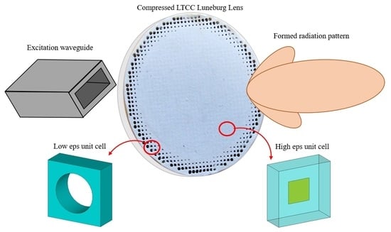
In this paper, we address the challenge of building a solid metamaterial-based lens at 60 GHz. The low-temperature co-fired ceramics (LTCC) process is employed to ensure the appropriate tolerance and robustness of implementing a compressed Luneburg lens antenna operating at 60 GHz. The LTCC process allows further integration of the lens in an antenna-in-package solution and is of great interest for such lens antenna development.
The initial theoretical development of the structure was presented in [
15]. The main contributions of this paper are summarized as follows:
The paper significantly expands the design study by including a parametrical analysis of various aspects of the compressed lens and their effect on the LTCC lens performance.
This paper presents details of the manufacturing of the LTCC lens and low-permittivity metamaterials in particular.
A novel method of the near-field measurements of the 60 GHz lens is presented in the paper.
Measurement results that verify the initial theoretical design proposed in [
15] are also presented in this paper.
The paper is organized as follows:
Section 2 discusses details of the compressed Luneburg lens antenna design in the LTCC process,
Section 3 explores the compressed Luneburg lens antenna characteristics through full-wave simulations;
Section 4 covers the fabrication aspects and
Section 5 discusses the measurement techniques and results.
2. LTCC Compressed Luneburg Lens Design
The spherical Luneburg lens is a gradient index lens with relative permittivity varying radially as described by [
16]:
where
R is the lens radius and
r is the radial position inside the lens (see
Figure 1a).
In order to reduce the volume of the lens and make it more compatible with various types of feeding antennas and integrated electronics, the use of the transformation optics method has been proposed, and the lens was either partially or fully transformed to a cylindrical shape with a flat surface [
10,
12,
17,
18]. In this paper, we use the geometrical transformation presented in [
12,
18] to implement a compressed Luneburg lens as shown in
Figure 1b. Note that full transformation leads to a 3 × 3 tensor as described in [
18] and that further simplifications can be applied at the implementation stage based on the polarization:
where
is the half of the thickness of the compressed lens.
Applying the equations of transformation optics, one can calculate the permittivity and permeability distributions across the flat Luneburg lens [
12,
18]:
where coefficients
A and
B are defined as follows:
Based on the observations in [
12,
13,
18], it has been shown that we can consider only the ε
yy or ε
xx element of the full tensor for TM- or TE-polarization, respectively.
In our case, for a flat Luneburg lens with radius
R = 9.5 mm and compressed thickness 2
δ = 1.92 mm, the permittivity distribution for ε
yy was calculated as shown in
Figure 2. It can be seen that permittivity varies from 2 to 20.
The lens was designed to be implemented with the LTCC process with the host material Ferro A6M-E of ε
r = 5.9, loss tangent of 0.002 and layer thickness of 0.096 mm. In order to achieve the permittivity variation shown in
Figure 2, two types of unit cells with a period of 0.5 mm and thickness 0.192 mm were implemented (see
Figure 3). To obtain permittivity lower than 5.9, the unit cell was designed as a brick of the host material with a cylindrical hole, as shown in
Figure 3a. The increase in the diameter of the hole leads to a reduction in the effective permittivity of the unit cell.
To realize high permittivity values, a unit cell with a rectangular metal patch was utilized (
Figure 3b). The effective permittivity for both unit cells obtained with CST Microwave Studio is shown in
Figure 4. Minimal hole and patch dimensions of 0.1mm were kept to comply with the manufacturing process and to reduce the impact of the tolerance of the process on the performance of the manufactured lens.
Finally, the model for the LTCC Luneburg lens was assembled in CST Microwave Studio (see
Figure 5). One can see that most of the structure is composed of patch unit cells with the hole unit cells occupying a small area close to the outer surface of the lens. The dimensions of each patch and hole were chosen using data in
Figure 4 to realize the permittivity distribution in (3).
It has been noted elsewhere [
18] that for the compressed lens, the optimal focus is not at the surface of the lens but must be found empirically. In [
19], simulated results of directivity for different positions of the feeding patch antenna on an optical axis were presented. Recently, [
20] proposed a corrected approximation of the transformation optics for the metamaterial Luneburg lens that allows the placing of the focus of the compressed lens on the surface. The unit cell proposed in [
20] is rather complex due to the necessity to correctly approximate the full permittivity tensor. In our work, we used a simplified formulation from [
18] that allows the utilization of simpler unit cells, which is a more reliable and repeatable approach for manufacturing mm-wave metamaterials. This approach resulted in the focus outside of the lens, which was thoroughly investigated. Analysis of this topic as well as lens simulation results are presented in the next section.
3. EM Simulations
In this section, we perform a parametric study of the focal distance as well as the effect of the compression on the lens performance. The first step was to feed the lens with a plane wave to find the focal point. The simulations were carried out at 60 GHz with CST Microwave Studio.
The focal distance was defined as the distance between the center of the lens and the point with the maximum magnitude of the electric field along the optical axis of the lens. The compression factor was changed by varying the number of the unit cells
along the principal axis of the lens, by taking into account that
where
h is the thickness of a unit cell and
δ is half of the lens thickness. In the simulations,
h equals to 0.192 mm, which corresponds to two LTCC layers with a thickness of 0.096 mm.
Figure 6 shows the results of the plane wave simulations. It is demonstrated that the focal distance decreases with the number of layers. The nonlinear dependence manifests a larger deviation of the focal point from the lens surface for a higher compression of the lens. Further increasing the number of layers has been found to be infeasible as this would exceed the limitations set by the available in-house manufacturing process (for our facilities, maximum
= 10).
Another set of simulations was carried out by feeding the lens with an open-ended waveguide (OEWG) with a cross-section of 1.55 × 3.1mm. The distance to the feed and its lateral displacement are shown in
Figure 7. The lens on its own is broadband. Reflection coefficient bandwidth is defined only by the type of the feed. In our case, it corresponds to the OEWG.
The dependence of the gain on the number of unit cells and the distance to the feed are shown in
Figure 8. In our simulations, we used the realized gain as the metric that incorporates the effect of impedance matching as well. It can be seen that for the different numbers of unit cells in the lens structure, the optimal position of the feed changes. An increasing number of unit cell lenses leads to the position of the feed being closer to its surface. For instance, with an 8-layer lens, the distance to the feed is 9 mm; the same gain can be obtained with a 22-layer lens and a 5 mm distance to the feed. The simulations support our previous finding that the focal point moves away from the lens surface for lenses with higher compression.
The beam steering capability in such lens antenna systems is obtained by shifting the OEWG. This displacement leads to additional gain reduction due to inefficient illumination of the lens surface. To estimate the gain, simulations for the lens with the number of unit cell layers
= 10 with different displacements of the OEWG were carried out.
Figure 9 shows gain as a function of the OEWG shift along the optical axis of the lens (distance to the feed) and laterally (displacement of the feed). One can see that in order to effectively illuminate the surface of the compressed lens, it is necessary to increase the distance to the feed when the feed is laterally displaced.
In our case, a focus of 5.96 mm (where 0.96 mm is half the lens thickness and 5 mm is the distance between the lens surface and the OEWG) was chosen. Taking into account that in the case of a spherical lens, the focus is equal to its radius, an approximately 63.6% size reduction was achieved in our lens antenna system. Radiation pattern results for this focal distance and different OEWG displacements are presented in
Figure 10. In comparison with the OEWG without the lens, the antenna gain was enhanced by 11 dB to 16.8 dBi. In this particular case, the sidelobe level was 15 dB for a 0 mm OEWG displacement and around 10 dB for an OEWG laterally shifted by 5 mm. In addition, shifting the waveguide with a 2.5 mm step allowed overlapping radiation patterns at −2 dB level. Beamwidth and gain as a function of frequency are shown in
Figure 11. Since a lens is a wideband device, its gain increases with frequency, and a compressed lens exhibits the same tendency. The impedance matching mostly corresponded to one of the exciting waveguides and the return loss wasa better than 10 dB across the simulated frequency band (56–64 GHz).
4. Lens Fabrication
The Luneburg lens is fabricated in-house. All twenty layers were laser-cut to create the alignment holes and the metamaterial holes along the periphery of the lens radius. The metamaterial holes differ a little in diameter and position for every layer even though perfect symmetry is kept in the z-direction. The layer count starting at the bottom layer is 1A, 1B, 2A, 2B, to 10B, which is the top layer. The metamaterial pattern is radially symmetric, and a z-direction symmetry is obtained with its center at the intersection between layers 5B and 6A. The hole pattern of layers 1A and 1B is precisely the same as for layers 10A and 10B, respectively; likewise for layers 2A and 2B and layers 9A and 9B, etc. The same goes for the screen-printed metamaterial patches, where the same pattern is used on layers 1A and 10A, 2A and 9A and so forth. Ferro gold paste CN30-080M is used. No screen printing is performed on the B layers. All layers are presented in
Figure 12. Details of a layer pair are given in
Figure 13. As can be seen, the laser-cut holes of these two layers are the same. When stacked, the patches are located in the center of every layer pair.
After preparing the layers, stacking was made with the help of an alignment fixture, (see
Figure 14). For each stacked layer, HEC 2wt% (Hydroxyethyl-cellulose) was filled in the holes manually by using a spatula. This HEC material serves to protect the holes from collapsing during lamination. The method has been published in [
21]. After stacking, uniaxial lamination was performed at 70 °C with an applied pressure of 17 MPa for 5 min. Then, the lens was separated from the rest of the LTCC by laser. The last fabrication step was the firing at 850 °C peak temperature for 30 min. The finalized antenna is presented in
Figure 15. Some damage can be seen at the outer periphery of the lens. This may have some impact on the measured results.
5. Measurements
The measurement setup was based on a spatial scan with a 6-axis robot. The OEWG is connected to an RF generator, SMA100B, with an external multiplier to generate the 60 GHz. The RX probe, fixed to the arm of the robot, consists of a horn antenna with a harmonic mixer connected to an R&S FSV3000 spectrum analyzer. The measured 3D radiation pattern is calculated from planar scans in the near-field region. Only the magnitude measurement is performed. The phase distribution is then computed by applying an iterative Fourier Technic (IFT) from the measurement on two layers [
22]. The principle of phase extraction is shown in
Figure 16.
Measurements were carried out by feeding the lens with the OEWG through a piece of foam with 5 mm thickness, as shown in
Figure 17a. Two 100 × 100 mm planes are scanned above the lens at different heights.
Figure 17b shows the magnitude distribution of the electric field on the two layers at 1 mm and 15 mm above the lens, and the phase distribution is then computed from the IFT.
The measured 3D radiation pattern is computed from a classic near-field to far-field transformation available in Altaïr FEKO Software and is shown in
Figure 18. To analyze the scanning performance, the probe is moved along the 200 mm circle with a center at the top of the lens opposite the OEWG center. The radiation pattern was measured in the range between −45° and 45° for the Luneburg lens as well as the OEWG at 60 GHz, as shown in
Figure 19. It can be seen that the lens provides a 10 dB gain enhancement in comparison to the OEWG. The side lobe level for this sample is defined as 10 dB. By moving the OEWG along the lens, beam-steering capability is achieved. We can see from the measurements that a 5 mm shift of the feed leads to beam steering at 25 degrees with 1 dB scan loss. The total gain was measured and compared to the simulation in
Figure 19c. The broadside gain of the manufactured lens antenna was equal to 16 dBi at 60 GHz. Radiation efficiency of 89% and aperture efficiency of 28% were calculated at 60 GHz. The latter figure is explained by the non-optimal illumination of the lens area, which is reasonable as the source is moved across the surface of the lens to achieve beam steering.
Table 1 summarizes the key features of the LTCC-compressed lens and several comparable V-band lens antennas that aim for high-gain performance with the potential for multibeam or beam-steering operation. A 3D-printed 60 GHz Luneburg lens based on the infill density of the plastic is demonstrated in [
23]. A solid hemispherical plastic lens printed for integration with a transceiver was developed in [
24]. A molded plastic elliptical lens with circular waveguide feed and mechanical beam steering capacity was demonstrated in [
25]. A 3D-printed dielectric Fresnel-Zone Plate Lens (FZPL) antenna for use within the V-band spectrum is presented in [
26]. As per the table, the proposed lens operates on the same frequency range and exhibits comparable performance to other lenses. However, its reported size is considerably smaller, resulting in a notable impact on the overall antenna system size. This reduction in size could potentially lead to a more compact and efficient antenna design, making it a promising option for various applications.
6. Conclusions
A 60 GHz metamaterial compressed Luneburg lens designed compatible with the LTCC process has been proposed in this paper. The effect of the compression on the focal point as well as the performance of the lens fed by a laterally displaced OEWG was studied. It was shown that the focal point is placed outside the lens and depends on the number of LTCC layers. The gain of the lens is shown to be a function of the thickness of the compressed lens. It was also shown that the scan loss of 1 dB can be achieved within a 50° field of view with a maximum gain of 16.8 dBi.
The lens was manufactured using an in-house LTCC process and measured at 60 GHz using two-plane near-field scanning and a subsequent iterative IFT method. The measured results are in good agreement with the simulation, with a 16 dBi maximum gain at 60 GHz and 1dB scan loss achieved.
The LTCC process allows further integration of control elements and active circuitry to make use of the lens in a multi-beam standalone transceiver for mm-wave communications that will be explored in future work.


 ,
, 


