Abstract
A dual circular polarization Fabry–Pérot resonant antenna is proposed in this paper. The proposed antenna consists of a microstrip antenna radiator and meta-surface. Meta-surface is applied into the design of a Fabry–Pérot (FP) resonant cavity for generating two circularly polarized (CP) beams. When the meta-surface functions as a partially reflecting surface with a top C-gaps array, dielectric substrate with holes periodically arranged around the atoms and bottom metal plate with strip gaps, the proposed design would split an LP wave from the feed into the left-hand CP and right-hand CP waves by rotating the top C-gaps to form prescribed phase gradients. Simulation and measurement results show that the proposed antenna is capable of generating left-hand CP and right-hand CP radiation beams pointing at 18° and −18° at 14.9 GHz with a stable gain of over 22.7 dBic and an aperture efficiency of 25.7%. The proposed technique offers an efficient way to fulfill FP resonant antennas with specific characteristics using meta-surface for more advanced functionalities.
1. Introduction
Fabry–Pérot (FP) resonant cavities with generating circular polarization (CP) radiation beams have aroused significant interest in developing several wireless communication systems and radar applications. The CP feeds are the most common methods used to produce the CP beams in FP resonant antennas [1,2,3]. However, the design of the CP feeds is relatively complicated due to some drawbacks, such as the complicated structure and difficult realization [4]. Recently, the LP feeds have also been employed to realize the FP resonant cavities with the polarization transformation from line polarization (LP) to CP [5,6,7,8,9]. Zhang et al. proposed a novel polarization conversion meta-surface served as the partially reflecting surface (PRS) of an FP resonant for high gain CP radiation [7]. Yousef et al. demonstrated a dual-band FP cavity antenna that achieves a large axial ratio bandwidth by employing a high impedance surface to compensate the phase difference between the two LP components of the reflected waves from PRS [8].
The LP radiation produced by the tilted 45° feed can be transformed into CP radiation when adjusting the aspect ratio of PRS for different responses to two orthogonal LP components of the LP exciting field. In addition, the CP patches that remove both diagonals have been used to construct the PRS to successfully make an LP-fed FP resonator cavity work in CP. However, such designs cannot simultaneously generate both CP radiation beams with opposite helicities.
Meta-surfaces as a kind of artificial smart material have demonstrated the great capability of redirecting the radiation directions of the electromagnetic (EM) fields [10,11,12,13], where different phase gradients of meta-atoms over the PRS have been employed to produce steerable radiation patterns from FP resonant cavities. In the meantime, meta-surfaces have also shown themselves to be capable of converting the LP waves into different polarization states while tuning travelling directions of wave-fronts when rearranging the amplitudes and phases of two orthogonal LP components simultaneously [14,15,16].
In this paper, we introduce a meta-surface into an FP resonant cavity for generating two CP beams. When the meta-surface functions as a partially reflecting surface (PRS) with top C-gaps array, a dielectric substrate with holes periodically arranged around the atoms and bottom metal plate with strip gaps, the proposed design would split an LP wave from the feed into the left-hand CP and right-hand CP waves by rotating the top C-gaps to form prescribed phase gradients. The proposed technique offers an efficient way to fulfill FP resonant antennas with specific characteristics using meta-surface for more advanced functionalities.
2. Antenna Design and Structure
Figure 1 demonstrates the configuration of a meta-surface FP resonant cavity with an aperture of 130.56 × 130.56 mm2 for splitting an LP wave from the feed into dual CP dual-beams. The top-layer of C-gaps can receive the LP wave radiated by the feed and perfectly couple the LP wave into the top layer of C-gaps by the gap of the metal ground, then releasing them to form the LHCP and the RHCP waves by importing different rotation angles over the top layer of C-gaps. The feed of the slot coupling patch and side view of the meta-surface FP resonant antennas are also shown in Figure 1.
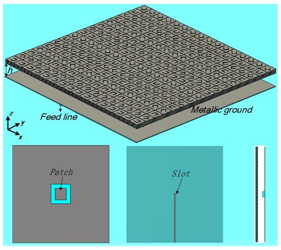
Figure 1.
Schematic diagram of the meta-surface FP resonant antennas.
As shown in Figure 2, the unit cell of meta-surface consists of the top layer of C-gap, the middle layer of the dielectric substrate with holes and the bottom layer of metal with strip gap, where such two-layer metal structures are separated by a substrate (εr = 3.5) and connected with holes periodically arranged around the atoms. In the meantime, the working frequency of the top layer of the C-gap is set in the high-frequency region so that only a part of the EM wave can be received at around 15 GHz and the remaining part will lead to multiple reflections between the meta-surface and the metal ground to improve the entire radiation of the proposed FP resonator antenna. A coupling patch antenna is employed as the feed to provide the LP waves required by the proposed radiator. Wp is the width of the coupling patch and Wl is the width of the stripe line.
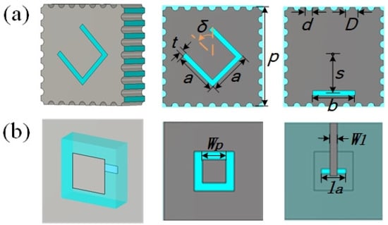
Figure 2.
Schematic diagram of the meta-surface FP resonator antenna. (a) The structural parameters of unit cell are a = 3.5 mm, d = 0.6 mm, D = 1.02 mm, p = 8.16 mm, and b = 3.47 mm, and all slits have a width of t = 0.4 mm. The C-gap in top layer is demonstrated to have a rotating angle of δ. (b) Feed of the slot coupling patch antenna with physical parameters of Wp = 4.7 mm, Wl = 1.46 mm, and la = 5 mm.
When the FP array is composed of only the C-shaped elements with a rotation angle of 0° and the resonant frequency of 15 GHz, the radiation far-field pattern is shown in Figure 3b. We can see from Figure 3c,d, the S11 of the FP array is below −10 dB near 15 GHz, meanwhile its maximum gain is up to 19 dBi at the corresponding frequency; the structure realizes linearly polarized high-gain radiation.
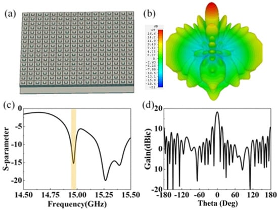
Figure 3.
(a) The array of the unit cell with δ = 0°. (b) Far-field 3D pattern of the FP antenna. (c) S11 of the FP antenna. (d) Far-field 2D patterns of the beam.
When the angle of the C-shaped slot is rotated and other parameters of the unit remain unchanged, the phase of the unit will change. When the unit is used to form an array according to a certain phase distribution, it can generate two orthogonal circularly polarized waves radiating in different directions. Figure 4 demonstrates the reflection and transmission characteristics of the meta-surface when changing the rotating angle of δ under the illuminations of the y-polarized EM wave. The reflection amplitude shows the partially transparent performance with reaching the minimum value of −3 dB at 15–16 GHz and has some small fluctuations when δ changes from 0° to 315°.
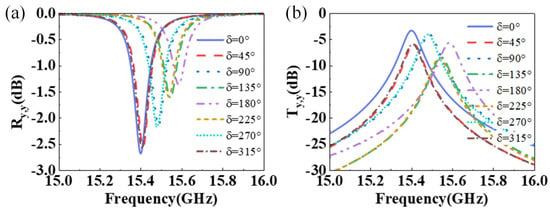
Figure 4.
Reflection and transmission characteristics of the meta-surface under the illumination of the y-polarized EM wave. (a) Reflection amplitude and (b) Transmittance amplitude with different oriented C-shape meta-atoms at 15–16 GHz, where Ry,y and Ty,y refer to the transmission coefficients of the y-polarized component.
The transmittance amplitude of the meta-surface in Figure 4b is also presented to show the partially transparent performance. Clearly, when δ changes from 0° to 315°, the corresponding operating frequency f between the offset is between 15.4 GHz and 15.6 GHz. Thus, we can obtain a stable cavity with a slot microstrip feed antenna of the same size as a meta-surface array for achieving the subsequent dual CP dual beams. In addition, only the portion of the energy can penetrate the meta-surface and the transmittance follow this relationship, when the rotating angle δ varies from 0° to 360°.
3. The Results of Proposed Antenna
Figure 5 demonstrates the radiation performances of the meta-surface-based FP resonant cavity. Figure 5 shows the radiation properties of the CP dual beams with θ = ±18° at 14.9 GHz. We can observe that the PRMS has been able to create both opposite phase gradients for generating the LHCP and RHCP waves, this is due to the fact that the C-shape meta-atom at each rotation angle contains two transmission phases φL and φR with opposite trends so that the radiation direction of the RHCP wave is exactly opposite when setting the radiation direction of the LHCP wave to θ = 18°. The full wave simulations (CST Microwave Studio) are then performed to verify the radiation performance of the PRMS-based FP resonant cavity. The cavity height h can be estimated through , (N = 0, 1, 2, …), where and are the reflection phases of the PRS and the metallic ground [17,18], respectively. Clearly, the reflection phase and the corresponding frequency f would fundamentally determine the height of the cavity. We optimized cavity height h, which would be 10.0 mm in this demonstration. Since the and h are frequency sensitive, the antenna has narrow band characteristics. We can observe from Figure 5a that the reflection coefficients can maintain less than −10 dB at near 14.9 GHz, and the maximum gain of the FP antenna is 22.7 dBic at 14.9 GHz. In the meantime, we can also observe that the FP resonant cavity perfectly splits the LP waves from the feed into LHCP and RHCP waves, and the maximum gains are 22.7 dBic at θ = −18° and 22.6 dBic at θ = 18°, then the corresponding axial ratios are 3.1 dB at −18° and 2.7 dB at 18°; such radiation angles have slight fluctuations relative to the theoretical design. We can observe from Figure 5d that the axial ratios with θ near to −18° and 18° at 14.9 GHz are below to 3 dB, and its circular polarization split beams effect is better than the corresponding axial ratio at 14.9 GHz. All of these results show the FP resonant cavity has been capable to realize the split LHCP and RHCP radiations.
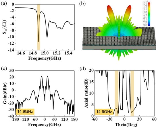
Figure 5.
(a) The S11 of the FP antenna for generating split CP dual beams in the direction of θ = ±18°. (b) Far-field 3D patterns of the split CP dual beams. (c) Far-field patterns in yx-plane of the split CP dual beams in the direction of θ = ±18° at 14.9 GHz. (d) Axial ratios of the FP antenna at 14.9 GHz.
Figure 6 demonstrates the influence of cavity height h on the operating frequency band and the radiation pattern of the meta-surface FP resonator antenna. We can observe in Figure 6a that the resonant frequency drops as the cavity height increases, with a shift of approximately 0.1 GHz occurring for every 0.1 mm increment in height. In the meantime, as shown in Figure 6b, the reduction in cavity height causes the FP resonator antenna to become poorly matched, resulting in a decrease in radiation gain.
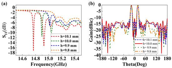
Figure 6.
(a) Reflection coefficients with different cavity heights. (b) Normalized far-field patterns in the yx plane with different cavity heights.
We fabricate the FP resonator antenna and experientially test the radiation performances, as shown in Figure 7. The substrate for the PRS is Teflon F4BM-2 material with a thickness of 1 = 1 mm ± 0.03, , and , the substrate for feed is also Teflon F4BM-2 material with a thickness of 2 = 3 mm ± 0.03, a thickness of 3 = 0.5 mm ± 0.03, , and . We can observe in Figure 7b that a resonant frequency occurs around 14.8 GHz, and the return loss (RL) is 21.4 dB, where the operating frequency experiences 0.1 GHz shift. The overall S11 is lower than the simulation, taking into account the material losses and the effects introduced by the test rig in the actual test. We can also observe that the FP resonator antenna splits the LP waves from the feed into LHCP and RHCP waves, and the maximum gain at 14.8 GHz are 22.1 dBic at and 24.5 dBic at .
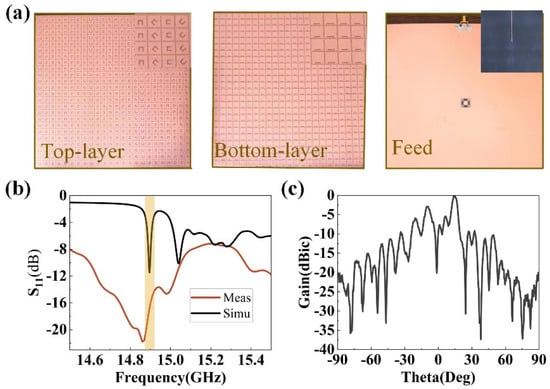
Figure 7.
The measurement of the FP resonator antenna. (a) Experimental setup photos. (b) Reflection coefficients. (c) Radiation patterns at 14.9 GHz.
The detailed comparisons with the previous publications concerning the FP resonator antennas are demonstrated in Table 1. The FP resonator antennas in [6] has high aperture efficiency but can only radiate single circularly polarized waves. Compared to the FP resonator antennas in [8,9], our proposed FP resonator antenna is capable of generating both LHCP and RHCP radiation beams with a single feed and has comparable gain and aperture efficiency to the antennas in the relevant literature.

Table 1.
Performance comparisons between Fp resonator antennas.
4. Conclusions
Therefore, the FP resonator composed of a partially reflective surface and a microstrip antenna can effectively convert the LP wave into two CP waves and radiate them in two different directions. The proposed design can split an LP wave from the feed into the left-hand CP and right-hand CP waves by rotating the top C-gaps arranged in a certain order to form prescribed phase gradients. Simulation and measurement results show that the proposed antenna is capable of generating left-hand CP and right-hand CP radiation beams pointing at 18° and −18° at 14.9 GHz with a stable gain of over 22.7 dBic. In addition, the different rotation angles of the C-shaped slits of adjacent units will lead to different demultiplexing angles. The proposed technique offers an efficient way to fulfill FP resonant cavities with specific characteristics using meta-surface for more advanced functionalities.
Author Contributions
Conceptualization, J.L. and X.H.; methodology, J.L.; software, J.L.; validation, J.L. and X.H.; formal analysis, X.H.; investigation, X.H.; resources, J.L.; data curation, J.L.; writing—original draft preparation, J.L.; writing—review and editing, J.L. and X.H. All authors have read and agreed to the published version of the manuscript.
Funding
This research received no external funding.
Data Availability Statement
The data presented in this study are available on request from the corresponding author.
Conflicts of Interest
The authors declare no conflict of interest.
References
- Liu, H.; Lei, S.; Shi, X.; Li, L. Study of antenna superstrates using metamaterials for directivity enhancement based on Fabry-Perot resonant cavity. Int. J. Antennas Propag. 2013, 2013, 209741. [Google Scholar] [CrossRef]
- Muhammad, S.A.; Sauleau, R.; Coq, L.L.; Legay, H. Self-Generation of Circular Polarization Using Compact Fabry–Perot Cavity Antennas. IEEE Antennas Wirel. Propag. Lett. 2011, 10, 907–910. [Google Scholar] [CrossRef]
- Yang, C.; Zhu, X.; Liu, P. A circularly polarized Fabry-Perot resonant cavity antenna using frequency selective surface-based partial reflecting surface. Int. J. RF Microw. Comput.-Aided Eng. 2021, 31, e22735. [Google Scholar] [CrossRef]
- Zeb, B.A.; Nikolic, N.; Esselle, K.P. A high-gain dual-band EBG antenna with circular polarization. IEEE Antennas Wirel. Propag. Lett. 2014, 14, 108–111. [Google Scholar] [CrossRef]
- Liu, Z.; Liu, S.; Bornemann, J.; Zhao, X.; Wang, D. A low-RCS, high-GBP Fabry–Perot antenna with embedded chessboard polarization conversion metasurface. IEEE Access 2020, 1, 99. [Google Scholar] [CrossRef]
- Xie, P.; Wang, G.; Li, H.; Liang, J.; Gao, X. Circularly polarized Fabry-Perot antenna employing a receiver–transmitter polarization conversion metasurface. IEEE Trans. Antennas Propag. 2019, 68, 3213–3218. [Google Scholar] [CrossRef]
- Zhang, X.; Chen, C.; Jiang, S.; Wang, Y.; Chen, A.W. A high-gain polarization reconfigurable antenna using polarization conversion metasurface. Prog. Electromagn. Res. C 2020, 105, 1–10. [Google Scholar] [CrossRef]
- Azizi, Y.; Komjani, N.; Karimipour, M.; Aryanian, I. Demonstration of a self-polarizing dual-band single-feed circularly polarized Fabry-Perot cavity antenna with a broadband axial ratio. AEU-Int. J. Electron. Commun. 2019, 111, 152909. [Google Scholar] [CrossRef]
- Liu, Z.; Cao, Z.; Wu, L. Compact low-profile circularly polarized Fabry-Perot resonator antenna fed by linearly polarized microstrip patch. IEEE Antennas Wirel. Propag. Lett. 2015, 15, 524–527. [Google Scholar] [CrossRef]
- Li, Z.; Liu, W.; Cheng, H.; Chen, S.; Tian, J. Tunable dual-band asymmetric transmission for circularly polarized waves with graphene planar chiral metasurfaces. Opt. Lett. 2016, 41, 3142–3145. [Google Scholar] [CrossRef]
- Huang, Y.; Yao, Z.; Hu, F.; Liu, C.; Yu, L.; Jin, Y.; Xu, X. Tunable circular polarization conversion and asymmetric transmission of planar chiral graphene-metamaterial in terahertz region. Carbon 2017, 119, 305–313. [Google Scholar] [CrossRef]
- Amin, M.; Siddiqui, O.; Abutarboush, H.; Farhat, M.; Ramzan, R. A THz graphene metasurface for polarization selective virus sensing. Carbon 2021, 176, 580–591. [Google Scholar] [CrossRef]
- Shrestha, V.R.; Craig, B.; Meng, J.; Bullock, J.; Crozier, K.B. Mid-to long-wave infrared computational spectroscopy with a graphene metasurface modulator. Sci. Rep. 2020, 10, 5377. [Google Scholar] [CrossRef]
- Long, M.; Jiang, W.; Gong, S.; Hong, T. Low-RCS frequency reconfigurable antenna with polarization conversion metasurface and phase tunable reflector. In Proceedings of the 2017 IEEE International Symposium on Antennas and Propagation & USNC/URSI National Radio Science Meeting, San Diego, CA, USA, 9–14 July 2017. [Google Scholar]
- Khan, M.I.; Fraz, Q.; Tahir, F.A. Ultra-wideband cross polarization conversion metasurface insensitive to incidence angle. J. Appl. Phys. 2017, 121, 045103. [Google Scholar] [CrossRef]
- Khan, M.I.; Fraz, Q.; Tahir, F.A. Linear and circular-polarization conversion in x-band using anisotropic metasurface. Sci. Rep. 2019, 9, 4552. [Google Scholar] [CrossRef] [PubMed]
- Wu, Z.; Zhang, W. Broadband printed compound air-fed array antennas. IEEE Antennas Wirel. Propag. Lett. 2010, 9, 187–190. [Google Scholar] [CrossRef]
- Yang, P.; Yang, R. Two-dimensional frequency scanning from a metasurface-based Fabry-Pérot resonant cavity. J. Phys. D Appl. Phys. 2018, 51, 225305. [Google Scholar] [CrossRef]
Disclaimer/Publisher’s Note: The statements, opinions and data contained in all publications are solely those of the individual author(s) and contributor(s) and not of MDPI and/or the editor(s). MDPI and/or the editor(s) disclaim responsibility for any injury to people or property resulting from any ideas, methods, instructions or products referred to in the content. |
© 2022 by the authors. Licensee MDPI, Basel, Switzerland. This article is an open access article distributed under the terms and conditions of the Creative Commons Attribution (CC BY) license (https://creativecommons.org/licenses/by/4.0/).