Abstract
Based on the voltage threshold adaptive memristor (VTEAM) model, this paper proposes a circuit design of a memristor-based A/D converter, which can achieve high-resolution conversion by simple configuration. For this A/D converter, there are the input voltage stage and the reference voltage stage in one conversion. According to the memristance change in the two stages, the input analog voltage is converted as the corresponding digital value. In the input voltage stage, the memristance increases from the initial memristance. Meanwhile, the counter rises its value from zero to the maximum. Next, the memristance returns to the initial memristance in the reference voltage stage. At the same time, the counting value starts to increase from zero again. Then, the input analog voltage is mapped to the eventual counting value of the reference voltage stage. The simulations of the memristor-based A/D converter demonstrate that it has good conversion performance. The proposed memristor-based A/D converter not only has more brilliant performance than the CMOS A/D converter, but also has the advantages over existing memristor-based A/D converters of anti-interference ability and high resolution.
1. Introduction
Analog-to-digital (A/D) converters are widely used in the modern electronic circuit, which is an important component in the information processing system. If an analog signal needs to be converted more precisely, the A/D converter should have high-resolution conversion ability [1,2].
In 1971, L. O. Chua proposed the memristor in theory [3]. HP labs manufactured the first physical memristor in 2008 [4]. The memristor can be manufactured to a nano-size, and it has non-volatility [5,6]. When the voltage is applied to the memristor, the memristance can be changed [7,8]. Furthermore, the memristor has the advantages on operating at high switching frequency, realizing large-scale parallel computing, etc. [9,10]. Owing to these merits, the memristor has been widely applied to the neuromorphic system [11,12], logic circuit [13,14,15], D/A and A/D converters [16,17], etc. [18,19].
The majority of physical memristors are voltage-controlled memristors [20,21]. When the voltage on the memristor is greater than the positive threshold voltage or is smaller than the negative voltage, the memristance will increase or decrease. Otherwise, the memristance stays unchanged. The voltage threshold adaptive memristor (VTEAM) model is a voltage-controlled memristor model that can match the behaviors of different memristors by changing the parameters [22,23,24,25].
Up to now, there are a few studies on the circuit design of memristor-based A/D converters. The Hopfield neural network is capable of converting analog signals to digital forms by configuring the network parameters to special values [26]. Because the memristor has changeable memristance, the memristor-based Hopfield neural networks are designed to accomplish A/D conversion [27,28]. In [29], the proposed memristor-based neural network is trained at first. Then, the trained network is applied to realize A/D conversion.
Based on the threshold feature of the memristor, combining the unilateral conductivity of diode, a memristor-based A/D converter is proposed in [30]. The threshold voltage of the memristor is used as the minimum distinguishable voltage of the A/D converter. Due to the non-volatility of the memristor, the memristor-based A/D converter can achieve the A/D conversion and the result storage synchronously.
Based on the excellent properties of memristor, a memristor-based D/A converter is proposed in [16]. Further, the memristor-based D/A converter is applied as the component to construct a successive approximation register A/D converter.
However, there are some deficiencies in the existing memristor-based A/D converters. For memristor-based Hopfield neural networks in [27,28], the A/D conversion is realized only if the memristors are arranged to accurate special values. This is difficult to implement in the manufacture. The memristor-based neural network in [29] must be trained before the A/D conversion. The training process is difficult to implement. Once the resolutions of the memristor-based A/D converters in [27,28,29] require change, the memristor-based neural networks must be configured or trained again. Because the resolution of the memristor-based A/D converter in [30] is decided by the threshold voltage of the memristors, the resolution cannot be arranged. Moreover, the conversion result of the memristor-based A/D converter will become inaccurate when the threshold voltage of the memristors changes along with the operation. The memristor-based A/D converters in [27,28,29,30] are susceptible to noises.
Based on the VTEAM model, this paper proposes the circuit design of memristor-based A/D converter, which has good conversion performance. Compared with the memristor-based circuits in [27,28,29,30], the proposed memristor-based A/D converter can easily realize high-resolution conversion by setting the bits of the counter. Meanwhile, the proposed memristor-based A/D converter has good anti-interference performance. Compared with A/D converters in [27,28,29], the memristor in the proposed memristor-based circuit can be arranged to random memristance in the manufacture, simplifying the fabrication process. Compared with the COMS dual-slope A/D converter, the proposed memristor-based A/D converter has a simpler circuit structure and timing.
The rest of the paper is organized as follows. Section 2 presents the circuit design and the conversion process of the memristor-based A/D converter. Section 3 shows the circuit simulations to prove the performance of the memristor-based A/D converter. The anti-interference of the memristor-based A/D converter is presented in Section 4. Section 5 presents the comparisons between the A/D converters. Conclusions are drawn in Section 6.
2. The Memristor-Based A/D Converter
2.1. Circuit Implementation of the Memristor-Based A/D Converter
The most physical memristors are voltage-controlled memristors. The VTEAM model is a general voltage-controlled memristor model [22]. The VTEAM model is given by
where represents memristance, and and denote the minimum and maximum memristance, respectively. and are the bounds of the internal state variable, and and represent the negative threshold voltage and the positive threshold voltage, respectively. , , , and are constant parameters.
The schematic diagram of the proposed memristor-based A/D converter is shown in Figure 1, in which is the analog input voltage and is the negative permanent reference voltage. The resistors , , , , and operational amplifier constitute a subtracting circuit, obtaining the difference between and . The output voltage of can be represented as
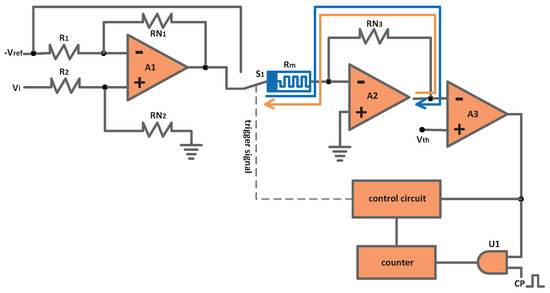
Figure 1.
The schematic diagram of the memristor-based A/D converter.
When the resistance of is one half of ’s resistance, and the resistance of is twice that of ’s resistance, Equation (3) can be simplified as
Either the output of or the reference voltage is linked to the memristor through the selector switch . Because the output of should be larger than the positive threshold voltage to increase the memristance, the input voltage to be converted must be greater than +.
Memristor , resistor , and operational amplifier constitute an inverting amplifying circuit. Due to , the voltage at inverting terminal of is 0 V. When the output of is linked to the memristor, the current flows to the inverting terminal of , making the memristance rise. The corresponding current path is presented as the blue line in Figure 1.
Alternatively, when is connected to the memristor, the current flows from the output terminal of , through and , to . Therefore, the memristance reduces. The orange line in Figure 1 shows the corresponding current path.
The output of connects to the inverting terminal of the comparator . The comparator generates the corresponding digital logic signal to enable or disable the AND gate . If the output of is 1, the AND gate is enabled. Then, the digital clock source serves as the counting clock of the counter. The output of the counter returns to the control circuit to generate the trigger signal, controlling the selector switch .
Compared with the CMOS dual-slope A/D converter, the proposed memristor-based A/D converter in this paper has a more compact control circuit structure, and has the simpler control timing [31,32]. Compared with the memristor-based A/D converter in [17], the proposed A/D converter in this paper adopts the VTEAM model to construct the circuit. The VTEAM model can match a number of voltage-controlled physical memristors, so the proposed A/D converter has the more flexible application potential.
2.2. Inference of Conversion Result
For the proposed memristor-based A/D converter, one conversion contains two stages: input voltage stage (IVS) and reference voltage stage (RVS). In IVS, the count value is reset to zero firstly. The analog input voltage adds to obtain the output of , . Then, the selector switch connects to the memristor to raise the memristance. Because is a positive voltage, the output of is a negative voltage
where denotes the memristance of . The threshold voltage of the comparator is positive, which is larger than . Thus, AND gate is enabled.
According to the digital clock source CP, the counting value increases from zero to the maximum in IVS. The duration of IVS can be represented as
where is the cycle of CP. Once the counting value attains the maximum , IVS finishes. Then, the memristor-based A/D converter enters RVS.
During RVS, the reference voltage is connected to the memristor. The voltage across the memristor is negative. Thus, the memristance decreases. Due to the connection of the negative voltage , the output of hops to a positive voltage at the start of RVS
In the beginning, the threshold voltage of the comparator is still larger than the output voltage of , . Hence, the AND gate remains enabled. Accordingly, the counter begins counting from zero again. The memristance reduces and increases in RVS. When rises to be equal to , the comparator outputs a low level afterwards. Then, the AND gate is disabled. The counting stops, and the conversion comes to the end. The duration of RVS is given by
where is the eventual counting value of RVS. At the end of the conversion, is equal to . In accordance with (7), the memristance at the end of the conversion can be deduced as
In the proposed memristor-based A/D converter, the reference voltage, the threshold voltage of the comparator , and the resistance of are fixed parameters. Accordingly, is a definite constant. At the end of every conversion, the memristance returns to . At the same time, is the initial memristance of the next conversion. Due to the non-volatility of memristor, the eventual memristance remains, even if the power turns off.
In one conversion, the memristance rises from the initial memristance to a value marked as in IVS, and then it reduces from to in RVS. The increment and decrement of the memristance are the same in the two stages.
is linked to the memristor in IVS to increase the memristance with . The increment of the memristance in is the total influence of . If is a varying voltage in IVS, the effect of can be equivalent to that of ’s average voltage. Therefore, the conversion obtains the average voltage of in IVS, .
If the analog input signal has mixed the sine noise, white Gaussian noise, or other zero-mean noises, the influence of the noise signals is weakened greatly by the average function in IVS. As a consequence, the proposed memristor-based A/D converter has good anti-interference performance to zero-mean noises. Nevertheless, the conversion results of the memristor-based A/D converters in [27,28,29,30] are susceptible to noises.
The reference voltage is connected to the memristor in RVS. The , , , , , and are constant parameters in the VTEAM model. Furthermore, and are fixed voltages. Under the influence of and , the VTEAM model is simplified as
Accordingly, (10) can be solved as
where represents the initial state variable. Thus, the memristance change can be represented as
where represents the initial memristance.
In IVS, affected by , the memristance increases from to during
In RVS, under the influence of the reference voltage , the memristance reduces from to during
The relation between and can be inferred by associating (13) and (14)
Combining the presentation in (1), Equation (15) can be rewritten as
Then, can be obtained by solving (16)
is the average voltage of in IVS. The average voltage of in IVS is marked as . Thus, can be represented as
As we can see in (18), the conversion result is the average voltage of the analog input voltage. Hence, the proposed memristor-based A/D converter is suitable to convert the input signal that changes relatively slowly. Then, the conversion result can reflect to the analog input voltage effectively.
As shown in (18), , , , , and are constant parameters. Hence, the conversion result is determined by the counting value . In order to ensure the correctness of the conversion result, must be less than the maximum counting value. In accordance with (16), when is less than the maximum counting value, the parameters of the memristor-based A/D converter must satisfy
Based on the presentation in (19), the analog input voltage range can be calculated when the parameters of memristor and the reference voltage are selected.
According to the previous analysis, the conversion result is decided by the eventual counting value . If the counter is arranged to different bits, the resolution of the proposed memristor-based A/D converter is adjusted accordingly. For instance, the 16-bit counter indicates that the resolution is 16 bits while the 12-bit counter corresponds to 12-bit resolution. Therefore, the proposed memristor-based A/D converter can achieve high-resolution conversion easily.
However, the memristor-based A/D converter in [30] is unchangeable. Additionally, the conversion result in [30] becomes unreliable when the threshold voltage of the memristors changes along with the usage. The memristor-based A/D converters in [27,28,29] are difficult to realize high-resolution conversion, because the tremendous parameter configurations or computations are required to make the memristor-based neural networks converge to correct digital states. The memristor-based A/D converters in [27,28,29,30] are vulnerable to noises.
3. Simulations of the Memristor-Based A/D Converter
The simulations of the proposed memristor-based A/D converter with different parameters are implemented on SIMULINK to demonstrate the conversion performance. The simulations are fulfilled with four different parameters, which are shown in Table 1. Although the parameters of the memrsitor are arranged to different values, the conversion results of the input voltage 1V are the same. These simulations demonstrate that the conversion results of the proposed memristor-based A/D converter are not affected by the different parameter settings of the memristor.

Table 1.
The parameter settings of the memristor.
In the simulations, the initial memristance is 45 k. The counter is 16 bits, which indicates that the resolution of the A/D converter is 16 bits. The frequency of the digital clock source is set as 2 MHz. The input voltage to be converted is 1 V, while the reference voltage is −6 V.
In the fourth simulation, the parameter settings of and are 3 and 2. The threshold voltage of the comparator is 3.5 V. The resistance of is 26 k. Hence, based on the relation presented in (9), the initial memristance is 44.571 k.
The memristance variation and the output voltage change in the fourth simulation are shown in Figure 2. The fourth simulation includes three conversions. X is invalid, while 1 and 2 are effective. Because the arranged initial memristance 45 k is not equal to the effective initial memristance 44.571 k, the memristor-based A/D converter requires the transitional X to enter the effective conversions.
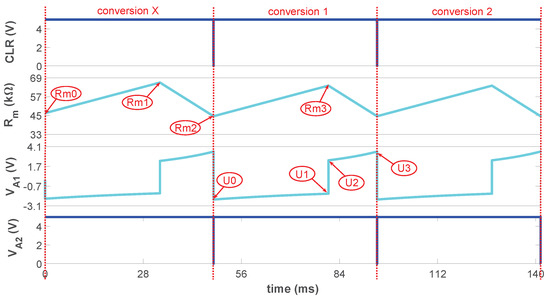
Figure 2.
The memristance variation and the output voltage change in the fourth simulation.
In X, the input voltage is applied to the memristor-based A/D converter in IVS. Accordingly, the memristance begins to increase from the arranged initial memristance 45 k, which is marked as in Figure 2. The counting value rises from 0 to the maximum. Thus, the IVS lasts 32.768 ms, and the memristance increases from to .
In RVS of X, the reference voltage −6 V is connected to the memristor-based A/D converter. The counting value increases from 0 again and the memristance decreases from . When the memristance reduces to the effective initial memristance 44.571 k, which is marked as in Figure 2, the X goes to the end. Relying on the invalid transition X, the proposed memristor-based A/D converter adjusts to the effective transformation. Then, the memristor-based A/D converter begins to convert the analog input signal validly. Because the memristor is nonvolatile, the valid memristance remains, even though the power supply turns off.
At the beginning of 1, the signal resets the counter to zero. In the IVS of 1, the memristance increases from to . At the same time, rises from to . Next, it enters the RVS of 1. The reference voltage is linked into the memristor-based A/D converter immediately. Therefore, hops to . The memristance decreases from to , and increases to in RVS. The memristance variation and the output voltage change in 2 are same as those in 1. The conversion results of 1 and 2 are 0.999 V.
Based on the previous analysis, we can see that the proposed memristor-based A/D converter can adjust to the effective conversion depending on the transitional transformation when the memristance is not manufactured to the accurate 44.571 k. Further, if the memristor is fabricated to the arbitrary memristance in the manufacture, the memristor-based A/D converter also can automatically proceed to the available conversion by the invalid transformations. In the condition that the memristance is manufactured to approach the minimum, the IVS becomes the dominant factor in the ineffective transformations to continuously increase the memristance. After several invalid conversions, the memristance increases to the effective initial memristance 44.571 k. On the other hand, when the memristance is fabricated to near the maximum, the RVS dominantly affects the ineffective conversions, making the memristance reduce to 44.571 k.
However, for the memristor-based Hopfield neural networks in [27,28], only when all the memristors are manufactured to the accurate memristance can the correct conversion be realized. Thus, the manufacture process is complicated.
Further, the analog input voltage is arranged to different values in the input voltage range. Then, a great number of simulations are implemented with the different analog input voltages to prove the conversion performance of the memristor-based A/D converter. Applying the final counting values of the conversions as the x axis, the corresponding conversion results that are computed by (18) are utilized as the y axis to obtain the fitting conversion curve of the simulations, which is presented as red in Figure 3. Moreover, the ideal conversion curve marked as blue is also presented in Figure 3. As we can see, the conversion curve of the simulations almost superposes the ideal conversion curve. Consequently, the conversion results of the simulations demonstrate that the memristor-based A/D converter has good transformation performance.
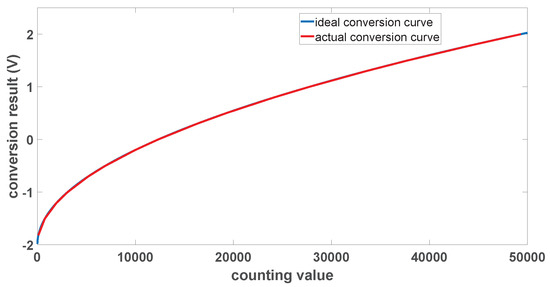
Figure 3.
The conversion curve of the memristor-based A/D converter.
4. Anti-Interference Performance of the Memristor-Based A/D Converter
The conversion result of the memristor-based A/D converter is the average voltage of the input signal. If the zero-mean noise is superposed on the actual analog input signal to be the input signal, the influence of the noise is weakened effectively. Thus, the memristor-based A/D converter has the ability to prevent the interference of the zero-mean noise.
The memristor-based A/D converter is simulated on SIMULINK to prove the anti-interference performance. In the simulation, the sine noise whose amplitude is 1 V is superposed to the 0 V actual analog voltage, acting as the input voltage. The frequency of the sine noise is 300 Hz. The counter is arranged as 16 bits, and the frequency of the counting clock source is 2 MHz. Hence, the IVS lasts 32.768 ms. Ten cycles of the sine noise last 33.33 ms, which approaches the duration of the IVS. Then, the mean of the sine noise in IVS is close to zero, and the influence of the sine noise is notably weakened. The memristance change and the output variation under the input voltage with sine noise are presented in Figure 4.
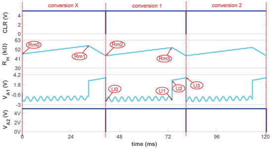
Figure 4.
The memristance variation and the output voltage change under the input voltage with sine noise.
There are three conversions in Figure 4. The memristor-based A/D converter begins to convert the input signal effectively depending on the invalid transformation X. 1 is effective, and the initial memristance of IVS is . The memristance at the end of IVS is . Affected by the input signal with sine noise, the increase in the memristance has little fluctuations. Because the input signal is sine voltage, combining with the variation of the memristance, the output voltage of amplifier A1 presents an analog sine change in IVS. According to (19), the conversion result is calculated as 0.109 V.
Then, the sine noises whose amplitudes change within 0.2–1.2 V are added to the actual 0 V analog voltage to implement the simulations. The interval of the sine noises’ amplitude is 0.2 V. The corresponding conversion results are given in Table 2. As we can see in the table, the corresponding conversion results indicate that the influences of the sine noises are shortened notably.
Table 2.
The conversion results of the 0 V analog voltage with the sine noises.
Further, the actual analog voltage is arranged as 1 V. The different sine noises are superposed to the 1 V analog voltage to implement the more simulations. The frequency of these sine noises is 3000 Hz and the amplitudes of these sine noises also change within 0.2–1.2 V. The corresponding conversion results are shown in Table 3, which demonstrate that the effects of these sine noises are weakened validly.
Table 3.
The conversion results of the 1 V analog voltage with the sine noises.
As shown in the previous simulations, as long as the duration of IVS is arranged to approach the cycles of the sine noises, even though the sine noises have different amplitudes and frequencies, the influences of the sine noises have been shortened notably. This proves that the proposed memristor-based A/D converter has good anti-interference ability to prevent the zero-mean noises. However, the memristor-based A/D converters in [27,28,29,30] are susceptible to noises.
5. Discussion
Compared with the existing memristor-based A/D converters and the CMOS dual-slope A/D converter, the proposed memristor-based A/D converter has the advantages of different aspects. The corresponding comparisons are shown in Table 4.
Table 4.
The comparisons of the A/D converters.
For the CMOS dual-slope A/D converter [31,32], it must discharge the capacitor at the beginning of every conversion. Then, it needs the corresponding control circuit to manage the discharging timing. However, the proposed memristor-based A/D converter does not require this discharging operation. Therefore, the proposed circuit has the simper circuit structure and timing.
The memristor-based A/D converters in [27,28] must manufacture the memristors to accurate values while the memristor in the proposed circuit can be manufactured to a random value. Hence, the manufacture of the memristor in this paper is simple. For the memristor-based A/D converters in [27,28,29], they are difficult to realize high resolution because there will be a large number of parameters to be configured or trained. When the input signal mixes in noises, the noises can make the memristor-based neural networks in [27,28,29] converge to incorrect digital values.
The resolution of memristor-based A/D converters in [30] is unchangeable. Meanwhile, the threshold voltage of the memristors must be manufactured to be strictly equal. Thus, the manufacture of the memristors is complex. If noises are mixed into the input signal, the memristors can be changed to a false state, generating the wrong conversion result. Compared with the memristor-based A/D converters in [27,28,29,30], the proposed circuit in this paper has good anti-interference ability to prevent zero-mean noises. The memristor-based circuit design in [30] utilizes the HP memristor model to fulfill the conversion. However, this paper adopts the VTEAM model, which is a voltage-controlled memristor model. A majority of physical memristors are voltage-controlled memristors. Hence, the proposed memristor-based A/D converter in this paper has the more extensive application potential.
The CMOS successive approximation register (SAR) A/D converter and the CMOS dual-slope A/D converter are two high-resolution A/D converters. Meanwhile, the SAR A/D converter can convert the analog signals relatively fast. However, the SAR A/D converter does not have anti-interference ability. Hence, the SAR A/D converter and the CMOS dual-slope A/D converter are applied to different occasions [31,32]. Accordingly, the memristor-based SAR A/D converter in [16] and the proposed memristor-based A/D converter in this paper also have different application occasions.
6. Conclusions
The A/D converter plays an important role in the modern circuit. This paper proposes a novel memristor-based high-resolution A/D converter in which one conversion contains IVS and RVS. Then, the memristance variation and the output voltage change are analyzed to illustrate the A/D conversion process. At the same time, the relation between the input voltage and the digital counting value is inferred according to the circuit parameter changes. The memristor-based A/D converter is simulated on SIMULINK to prove the performance. Under different parameter settings, a great number of simulations are implemented to obtain the conversion curve of the memristor-based A/D converter. Further, the memristor-based A/D converter is analyzed and simulated to prove its anti-interference ability for zero-mean noise. The comparisons between the proposed memristor-based A/D converter and the existing A/D conversion circuits are also presented to demonstrate the advantages of the proposed circuit. Implementing the proposed memristor-based A/D converter with real memristors will be studied in the future.
Author Contributions
Conceptualization, L.Y.; methodology, L.Y. and Z.D.; software, L.Y.; data curation, L.Y.; writing—original draft preparation, L.Y. and Z.D.; writing—review and editing, L.Y. and Z.D. All authors have read and agreed to the published version of the manuscript.
Funding
This research was funded by the National Key R&D program of China under Grant 2018YFB1305500, the Technology Innovation Project of Hubei Province of China under Grant 2019AEA171, the National Natural Science Foundation of China under Grants 62106181, 62176189 and 62176163, the Science Foundation of Wuhan Institute of Technology K202017, the Hubei Key Laboratory of Intelligent Robot (Wuhan Institute of Technology) under Grant HBIRL202109. The APC was funded by the Science Foundation ofWuhan Institute of Technology K202017.
Institutional Review Board Statement
Not applicable.
Informed Consent Statement
Not applicable.
Data Availability Statement
Not applicable.
Conflicts of Interest
The authors declare no conflict of interest.
References
- Rombouts, P.; De, W.W.; Weyten, L. A 13.5-b 1.2-V micropower extended counting A/D converter. IEEE J. Solid-State Circuits 2001, 36, 176–183. [Google Scholar] [CrossRef]
- Fahmy, G.A.; Pokharel, R.K.; Kanaya, H.; Yoshida, K. Indirect compensation technique based two-stage recycling folded cascode amplifier for reconfigurable multi-mode sigma-delta ADC. In Proceedings of the 2010 IEEE International Conference of Electron Devices and Solid-State Circuits (EDSSC), Hong Kong, China, 15–17 December 2010. [Google Scholar]
- Chua, L.O. Memristor-the missing circuit element. IEEE Trans. Circuit Theory 1971, 18, 507–519. [Google Scholar] [CrossRef]
- Strukov, D.B.; Snider, G.S.; Stewart, D.R.; Williams, R.S. The missing memristor found. Nature 2008, 453, 80–83. [Google Scholar] [CrossRef]
- Xia, Q.; Yang, J. Memristive crossbar arrays for brain-inspired computing. Nat. Mater. 2019, 18, 309–323. [Google Scholar] [CrossRef]
- Wang, K.; Hu, Q.; Gao, B.; Lin, Q.; Zhuge, F.W.; Zhang, D.Y.; Wang, L.; He, Y.H.; Scheicher, R.H.; Tong, H.; et al. Threshold switching memristor-based stochastic neurons for probabilistic computing. Mater. Horiz. 2021, 8, 619–629. [Google Scholar] [CrossRef]
- Yang, L.; Zeng, Z.; Huang, Y. An associative-memory-based reconfigurable memristive neuromorphic system with synchronous weight training. IEEE Trans. Cogn. Dev. Syst. 2020, 12, 529–540. [Google Scholar] [CrossRef]
- Hu, M.; Graves, C.E.; Li, C. Memristor-based analog computation and neural network classification with a dot product engine. Adv. Mater. 2018, 30, 1705914. [Google Scholar] [CrossRef]
- Sun, J.; Han, G.; Zeng, Z.; Wang, Y. Memristor-based neural network circuit of full-function pavlov associative memory with time delay and variable learning rate. IEEE Trans. Cybern. 2020, 50, 2935–2945. [Google Scholar] [CrossRef]
- Zhang, Y.; Wang, X.; Li, Y.; Friedman, E.G. Memristive model for synaptic circuits. IEEE Trans. Circuits Syst. II Exp. Briefs 2017, 64, 767–771. [Google Scholar] [CrossRef]
- Chen, L.; Li, C.; Chen, Y. A forgetting memristive spiking neural network for pavlov experiment. Int. J. Bifurc. Chaos 2018, 28, 1850080. [Google Scholar] [CrossRef]
- Shang, L.; Duan, S.; Wang, L.; Huang, T. SRMC: A multibit memristor crossbar for self-renewing image mask. IEEE Trans. Very Large Scale Integ. (VLSI) Syst. 2018, 26, 2830–2841. [Google Scholar] [CrossRef]
- Karimi, A.; Rezai, A. High-performance digital logic implementation approach using novel Memristor-based multiplexer. Int. J. Circ. Theor. Appl. 2019, 47, 1933–1947. [Google Scholar] [CrossRef]
- Karimi, A.; Rezai, A. Novel design for a memristor-based full adder using a new IMPLY logic approach. J. Comput. Eletron. 2018, 17, 1303–1314. [Google Scholar] [CrossRef]
- Karimi, A.; Rezai, A. Novel design for Memristor-based n to 1 multiplexer using new IMPLY logic approach. IET Circuits Devices Syst. 2019, 13, 647–655. [Google Scholar] [CrossRef]
- Fahmy, G.A.; Zorkany, M. Design of a memristor-based digital to analog converter (DAC). Electronics 2021, 10, 622. [Google Scholar] [CrossRef]
- Yang, L.; Zeng, Z.; Ma, Z.; Shan, W. A memristive dual-slope A/D converter. Int. J. Circuit Theory Appl. 2020, 48, 42–55. [Google Scholar] [CrossRef]
- Yang, Y.; Li, D.; Wang, D. Dynamic analysis of the switched-inductor buck-boost converter based on the memristor. Electronics 2021, 10, 452. [Google Scholar] [CrossRef]
- Wang, M.; Yan, Z.; Wang, T.; Cai, P.; Gao, S.; Zeng, Y.; Wan, C.; Wang, H.; Pan, L.; Yu, J.; et al. Gesture recognition using a bioinspired learning architecture that integrates visual data with somatosensory data from stretchable sensors. Nat. Electron. 2020, 3, 563. [Google Scholar] [CrossRef]
- Ostrovskii, V.; Fedoseev, P.; Bobrova, Y.; Cai, P.; Gao, S.; Zeng, Y.; Wan, C.; Wang, H.; Pan, L.; Yu, J.; et al. Structural and parametric identification of Knowm memristors. Nanomaterials 2021, 12, 63. [Google Scholar] [CrossRef]
- Aguirre, F.L.; Sune, J.; Miranda, E. SPICE implementation of the dynamic memdiode model for bipolar resistive switching devices. Micromachines 2022, 13, 330. [Google Scholar] [CrossRef]
- Kvatinsky, S.; Ramadan, M.; Friedman, E.G.; Kolodny, A. VTEAM: A general model for voltage-controlled memristors. IEEE Trans. Circuits Syst. II Exp. Brief 2015, 62, 786–790. [Google Scholar] [CrossRef]
- Yalon, E.; Gavrilov, A.; Cohen, S.; Mistele, D.; Meyler, B.; Salzman, J.; Ritter, D. Resistive Switching in HfO2 Probed by a Metal-Insulator-Semiconductor Bipolar Transistor. IEEE Electron. Device Lett. 2011, 33, 11–13. [Google Scholar] [CrossRef]
- Chanthbouala, A.; Garcia, V.; Cherifi, R.O.; Bouzehouane, K.; Fusil, S.; Moya, X.; Xavier, S.; Yamada, H.; Deranlot, C.; Mathur, N.D.; et al. A ferroelectric memristor. Nat. Mater. 2012, 11, 860–864. [Google Scholar] [CrossRef]
- Johnson, S.L.; Sundararajan, A.; Hunley, D.P.; Strachan, D.R. Memristive switching of single-component metallic nanowires. Nanotechnology 2010, 21, 125204. [Google Scholar] [CrossRef]
- Tank, D.; Hopfield, J. Simple neural optimization networks: An A/D converter, signal decision circuit, and a linear programming circuit. IEEE Trans. Circuits Syst. 1986, 33, 533–541. [Google Scholar] [CrossRef]
- Gao, L.; Merrikh, B.F.; Alibart, F.; Guo, X.; Hoskins, B.D.; Cheng, K.T.; Strukov, D.B. Digital-to-analog and analog-to-digit conversion with metal oxide memristors for ultra-low power computing. In Proceedings of the 2013 IEEE/ACM International Symposium on Nanoscale Architectures, Brooklyn, NY, USA, 15–17 July 2013; pp. 19–22. [Google Scholar]
- Guo, X.; Farnood, M.B.; Gao, L.; Hoskins, B.D.; Alibart, F.; Linares-Barranco, B.; Theogarajan, L.; Teuscher, C.; Strukov, D.B. Modeling and experimental demonstration of a hopfield network analog-to-digital converter with hybrid CMOS/memristor circuits. Front. Neurosci. 2015, 9, 488. [Google Scholar] [CrossRef]
- Wang, W.; You, Z.; Liu, P.; Kuang, J. An adaptive neural network A/D converter based on CMOS/memristor hybrid design. IEICE Electron. Expr. 2014, 11, 1–6. [Google Scholar] [CrossRef][Green Version]
- Pershin, Y.V.; Sazonov, E.M.; Di, V. Analogue-to-digital and digital-to-analogue conversion with memristive devices. Electron. Lett. 2012, 48, 73–74. [Google Scholar] [CrossRef]
- Kang, H. Fundamentals of Electronic Technology; Higher Educ Press: Beijing, China, 2006. [Google Scholar]
- Neamen, D.A. Microelectronics: Circuit Analysis and Design; McGraw-Hill: Boston, MA, USA, 2007. [Google Scholar]
Publisher’s Note: MDPI stays neutral with regard to jurisdictional claims in published maps and institutional affiliations. |
© 2022 by the authors. Licensee MDPI, Basel, Switzerland. This article is an open access article distributed under the terms and conditions of the Creative Commons Attribution (CC BY) license (https://creativecommons.org/licenses/by/4.0/).