Article

A Wide-Angle Pattern Diversity Antenna System for mmWave 5G Mobile Terminals

by
Karthikeya Gulur Sadananda
1,
Issa Elfergani
2,3,*,
Chemseddine Zebiri
4,
Jonathan Rodriguez
2,
Shiban Kishen Koul
5 and
Raed A. Abd-Alhameed
3,6
1
Centre for Antennas and Radio Frequency Systems, Department of Electronics and Telecommunication Engineering, Ramaiah Institute of Technology, Bengaluru 560054, India
2
Instituto de Telecomunicações, Campus Universitário de Santiago, 3810-193 Aveiro, Portugal
3
School of Engineering and Informatics, University of Bradford, Bradford BD7 1DP, UK
4
Laboratoired’Electronique de Puissance et Commande Industrielle (LEPCI), Department of Electronics, University of Ferhat Abbas, Sétif -1-, Sétif 19000, Algeria
5
Centre for Applied Research in Electronics, IIT Delhi, New Delhi 110016, India
6
Information and Communication Engineering Department, Basrah University College of Science and Technology, Basrah 24001, Iraq
*
Author to whom correspondence should be addressed.
Electronics 2022, 11(4), 571; https://doi.org/10.3390/electronics11040571
Submission received: 22 January 2022 / Revised: 9 February 2022 / Accepted: 10 February 2022 / Published: 14 February 2022
(This article belongs to the Special Issue Antenna Designs for 5G/IoT and Space Applications)

Abstract

:
A shared ground shared radiator with wide angular coverage for mmWave 5G smartphones is proposed in this paper. A four-element corporate-fed array with conventional impedance matched power divider is designed. Stepped impedance transformers are integrated with the corner most elements to achieve pattern diversity with wide angular coverage without significant compromise in gain. The proposed three-port shared radiator conformal commercial antenna could be easily integrated with commercial mmWave 5G smartphones. All the three ports’ excitations operate in the 28 GHz band. Radiation pattern bandwidth of the multi-port system is high. The gain variation is from 6 to 11 dBi amongst the ports and across the operating spectrum. The highest mutual coupling is 10 dB, in spite of the electrically connected structure. The proposed shared radiator element has a wide angular coverage of 100°, maintaining high front-to-back ratio when the respective port is excited. Simulation and measurement results for the proposed structure are illustrated in detail.

1. Introduction

Due to the tremendous growth in the smartphone data traffic, it is expected that millimeter waves would be useful for decongesting the current communication channels in the microwave domain [1,2,3]. Experimental characterizations have proved that higher frequency carriers could be well suited for cellular communication links [4,5]. Thus, exploration of hardware design centered at 28 GHz would be an important design topic. As per the Friis transmission formula [6], millimeter wave frequencies would experience additional losses due to the nature of the transmission link. It must also be noted that the real-world 28 GHz signal would suffer from additional losses due to the building materials and multipath effects [4]. Hence, high-gain antennas on the mobile phone are the only sensible choice to realize a mmWave link, given the constraints of the receiver sensitivity in the Ka-band.
Numerous articles and conference proceeding papers have been reported in the past decade. A high-gain corporate fed array is reported in [7], the electrical footprint is high and hence might not be suitable for direct integration with commercial 5G devices. Phased array presented in [8,9] is complex to fabricate and has low-gain yield for the electrical size occupied. Printed dipole of [10] would occupy a large footprint within the smartphone limits, proving to be unsuitable for the application at hand. The design reported in [11] lacks gain switch ability and is incompatible with the modern commercial smartphones.
Gain switch ability is required in mmWave 5G systems to cater to broadcast and data link modes. In the broadcast mode, a low-gain or wide-beam antenna is required and in the data link mode, a high gain or narrow beam is required. The same could be realized using phased arrays by selectively firing up the designated ports [10,11]. The CPW (coplanar waveguide)-fed antenna design of [12] works in the microwave band, the authors have demonstrated an orthogonal polarization system, but the same concept might not be applicable in the mmWave regime. Similarly, the design concept of [13] would lead to bidirectional radiation patterns, when the antenna is scaled up to millimeter wave frequencies. The corporate-fed array illustrated in [14] would occupy a larger physical footprint, when designed for the 28 GHz band. The MIMO concept illustrated in [15] might not be scaled down to Ka band. However, the design and deployment of phased arrays would be expensive. Therefore, an electrically compact three-port-wide angular coverage shared ground antenna system is proposed in this paper. The novel features of the proposed antenna design are listed below:
  • Shared radiator design with minimal physical footprint.
  • Shared ground design which is compatible with the system ground plane of the typical commercial device.
  • Conformal shared radiator design which could be panel mountable with commercially available smartphones.
  • Wide angular coverage with three ports without the use of phase shifters.
  • Achievement of high gain for the respective port for a minimal occupied physical footprint.

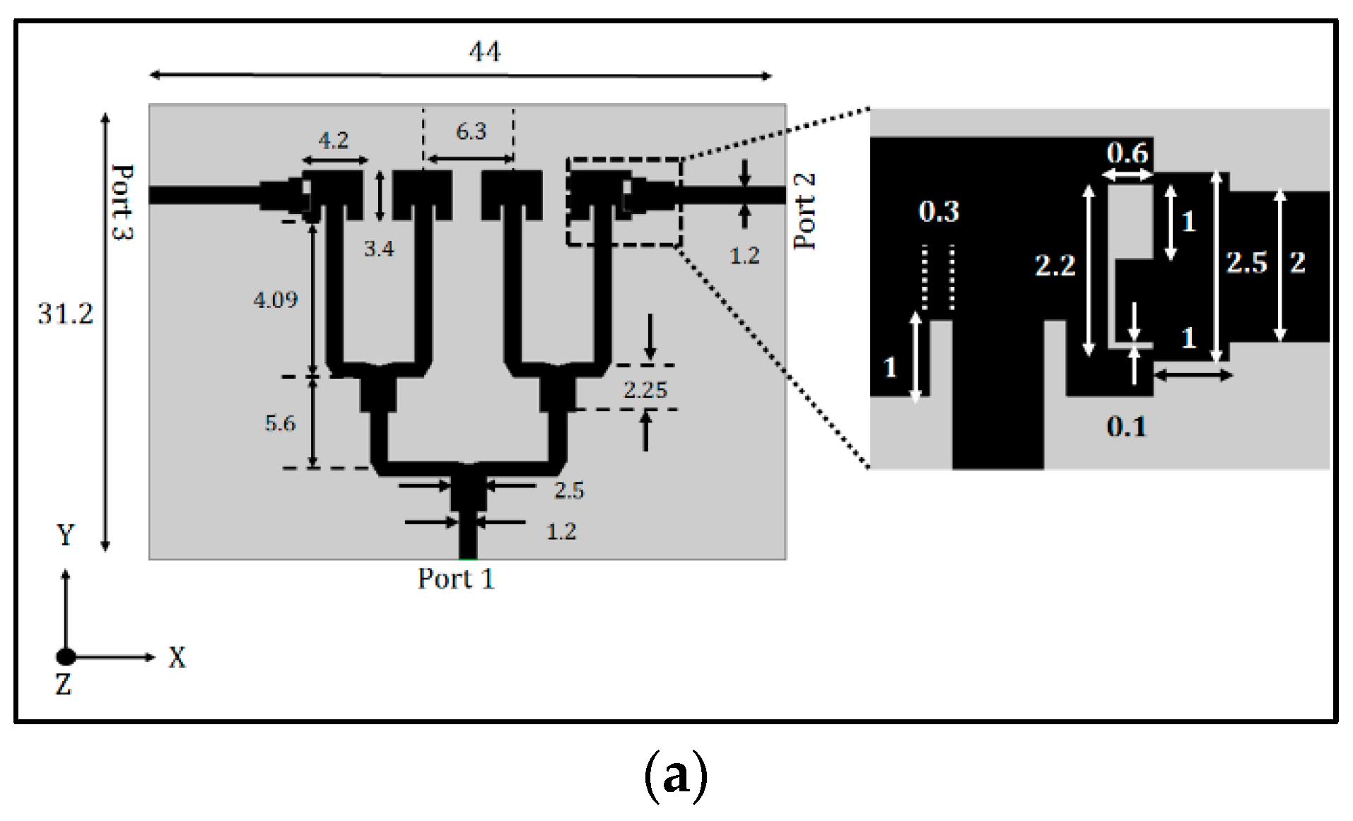
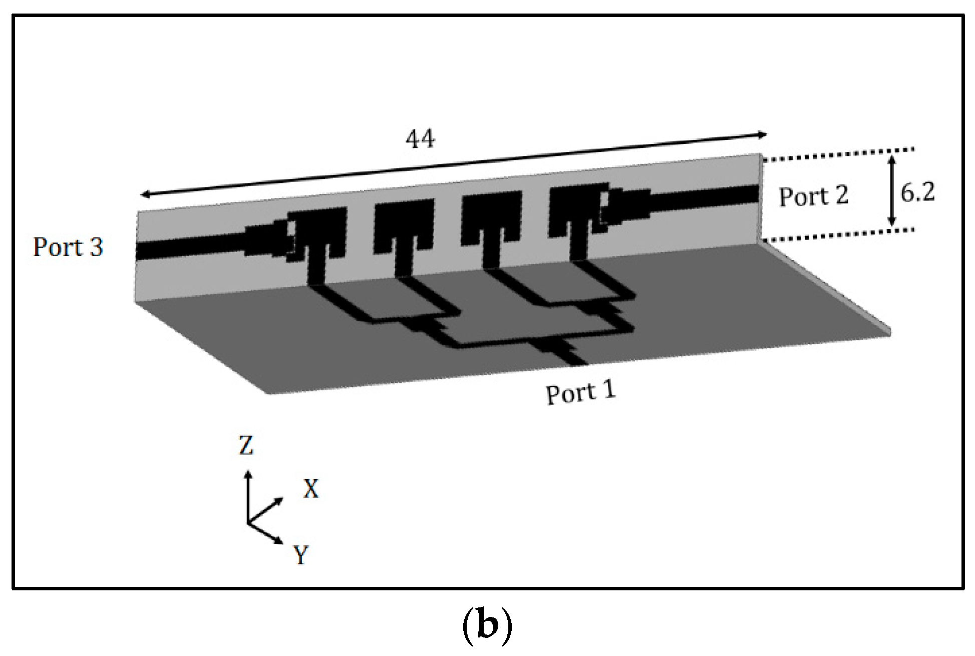
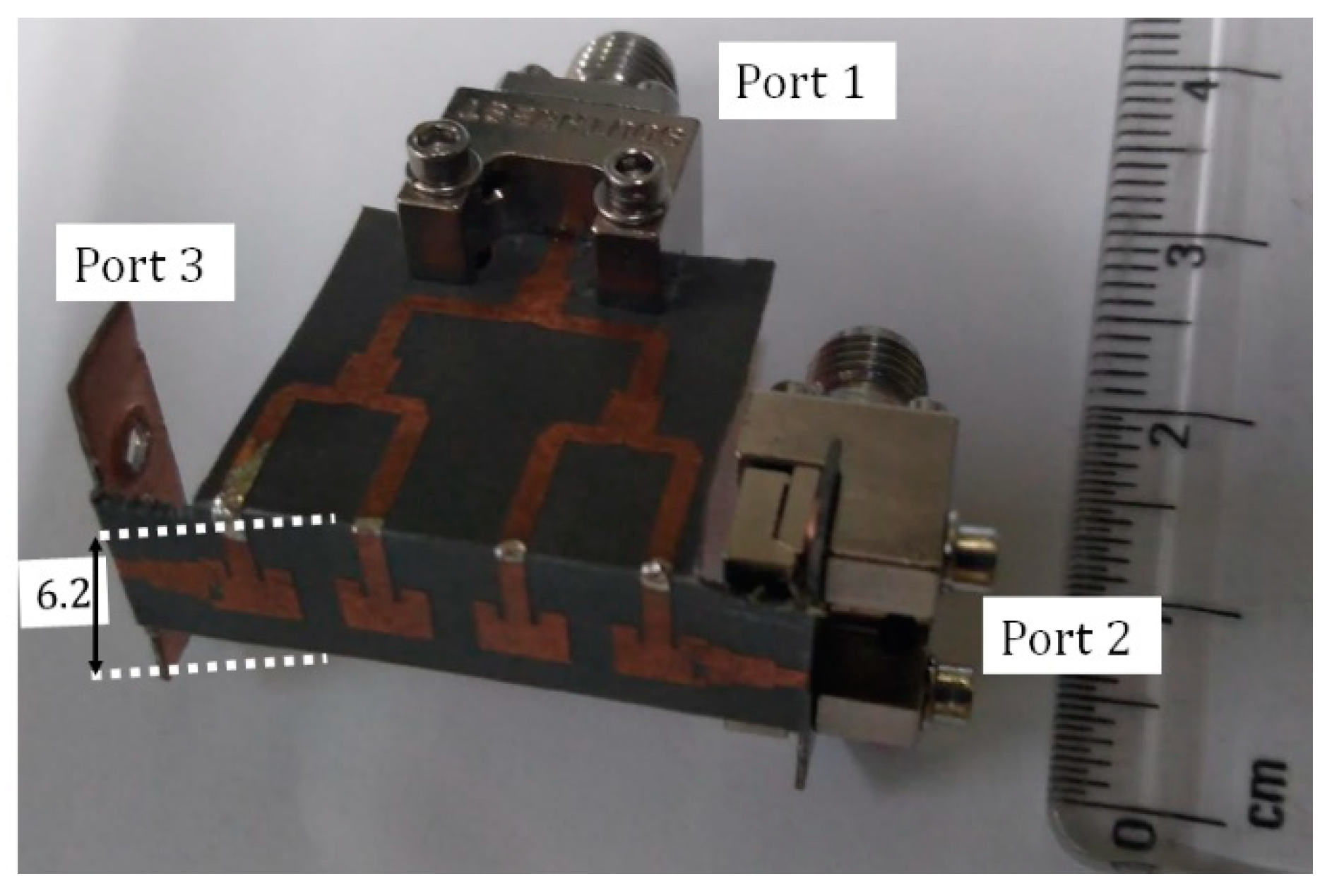
2. Proposed Pattern Diversity Antenna

The multiport electrically connected antenna system is displayed in Figure 1a. It is a corporate-fed, inset-fed patch antenna array [16,17,18,19] with multiple ports. The dielectric used to realize this microstrip-fed design is Rogers 5880, which has a dielectric constant of 2.2 ± 0.02 with a corresponding loss tangent of 0.0009. Lower dielectric constant is necessary to facilitate radiation, especially in the higher frequency of operation. It must also be noted that the forward gain loss due to higher dielectric loss tangent could be avoided by this substrate. Rogers substrate is not very flexible as the dielectric composition is rigid, but with a thickness of 20 mil, flexibility could be expected. However, this substrate cannot be bent and planarized multiple times as this would fracture the substrate and hamper the dielectric and metal integrity of the design.
The proposed design is an electrically connected multiport radiator with an electrically large ground with a conventional microstrip feeding technique. A 1.2 mm feed line has been incorporated to closely match the characteristic impedance SMA (sub-miniature A) connector. The entire structure is based on the corporate-fed array concept. Here, a four-element array is designed to achieve wide angular coverage as well as reasonably high gain for the available physical aperture. The feed line connects to a two-way non-Wilkinson-based power divider. A Wilkinson-based power divider would have enhanced the isolation between the terminated loads of the corresponding lines, the inset-fed patch antennas in this case. However, implementing a Wilkinson-based power divider at higher frequencies would be difficult due to the size of the miniature resistors and the requirement of a thin-tip solder. The notch at the T-junction of the power divider facilitates in impedance matching of the patch radiators and the feeding network. The primary radiators are spaced at an approximately half-wavelength distance on the substrate.
The outermost elements of the corporate-fed array are also connected to the ports, as observed in Figure 1a. These ports are connected to the edge along the Y axis of the corner most elements. The 50 Ω lines originating from ports 2 and 3 are impedance matched to the shorter edge of the radiator through two low impedance-stepped transformers. The 2.2 mm × 0.6 mm slot, displayed in the inset of Figure 1a, does not contribute to radiation due to the electrically small size of the slot. When port 2 is excited, the right corner element contributes to radiation and hence a low gain and wide beam is observed. The same phenomenon is observed when the connected structure is excited with port 3. As the corner elements are electrically away from the phase center of the corporate-fed array, beam tilt is expected for the corresponding port excitation.
The current design of Figure 1a would not be suitable for direct integration with the mobile terminal, as this would be a broadside radiator and the signal strength would drastically reduce when it is blocked by a human torso. Hence, the topology of placement of the proposed shared radiator must be such a way as to reorient radiation away from the user, when the antenna module is mounted on the mobile device. Hence, corner bent topology is investigated as illustrated in Figure 1b. Here, the height of the corner bent radiator is 6.2 mm, which is compliant with the industry standard height of 7 mm. It must also be noted that the proposed design has an electrically massive system ground plane; hence, it would be favorable for integration with commercial smartphones. The feeding network of the proposed topology is in the orthogonal plane as that of the radiating aperture. Hence, the geometry itself acts as an isolating network between the feed and the active radiating aperture. The design could be further miniaturized by bending the portion of the feeding structure of ports 2 and 3. A photograph of the fabricated prototype is illustrated in Figure 2.
The input impedance bandwidth corresponding to port 1 is 11.4%, centered at 28.1 GHz, as seen in Figure 3. The wideband characteristics are realized due to the topology of the feeding network and the impedance transformers at ports 2 and 3.
|S11| for ports 2 and 3 is graphed in Figure 4 and both are operational in the 28 GHz band. All the S-parameters measurements were performed using Agilent E8364C. It must be observed that the S-parameters’ measurements are difficult in the present context, as the connectors used are electrically large and are in close proximity with the antenna structure. The clearance for the connector cables is also very minimal; hence, the deviation between simulated and measured results are pretty evident. Additionally, the fabrication errors due to bending has resulted in the deviation between simulated and measured results.
The composite radiation patterns when the respective ports are activated are demonstrated in Figure 5. When port 1 is activated, the high-gain, low-beamwidth mode is activated. All four elements have in-phase E-fields which aid in beamforming leading to narrow beams. However, ports 2 and 3 have a wider beam, as the radiators on either edge are the primary contributors to the wide beam. The higher back lobe specifically for excitation of port 3 is due to the following reasons: Dual bending of the substrate which creates cracks within the copper trace of the feeding network, hence leading to radiation leakages from the discontinuities. Faulty assembly of the electrically large connector with the feeding line corresponding to port 3, leading to poor transition from the trace pin of the connector to the feed line. The overall angular coverage is 100° indicating a pretty wide angular coverage. The front-to-back ratio is greater than 10 dB and is maintained throughout the operating spectrum indicating minimal radiation towards the user.
The measured mutual coupling is less than 15 dB, as observed in Figure 6, in spite of the electrically connected geometry. The low mutual coupling is primarily due to the design of impedance transformers at ports 2 and 3. The forward gains of the designed antenna system is illustrated in Figure 7a, the radiation efficiency is shown in Figure 7b. The wider beams for ports 2 and 3 result in lower gain compared to its counterpart of port 1. An example placement of the proposed design with a commercial smartphone is demonstrated in Figure 8.
Table 1 illustrates various figures of merit of the proposed dual conformal antenna system in comparison to previously published designs. It is clear that the proposed system has wide angular coverage with a panel height less than 7 mm.

3. Conclusions

A three-port conformal antenna system operating in the 28 GHz is proposed, wherein a standard 50 Ω line is fed to the two-way power divider, which in turn is connected to the four-way power divider. The four-way power divider is loaded with four inset-fed patch antennas operating in the 28 GHz band. The corner elements of the corporate-fed array are in turn connected to the two ports through impedance transformers. Port 1 excitation would lead to a high-gain–narrow-beam mode preferable for a data link and ports 2 or 3 excitation would lead to a low-gain–wide-beam mode preferable for broadcast application. A wide angular coverage of 100° is achieved for various excitations of the ports within the shared radiator antenna system. Mutual coupling is less than 10 dB across the spectrum and across the ports, in spite of the electrically connected structure. The proposed antenna could be a potential candidate for future 5G applications.

Author Contributions

Conceptualization, K.G.S., S.K.K. and I.E.; methodology, K.G.S., I.E. and C.Z.; software, K.G.S. and C.Z.; validation, J.R., K.G.S. and I.E.; investigation, J.R. and K.G.S.; writing—original draft preparation, K.G.S. and S.K.K.; writing—review and editing, R.A.A.-A., I.E. and C.Z.; supervision R.A.A.-A. and I.E.; project administration, I.E. and J.R.; funding acquisition, J.R. All authors have read and agreed to the published version of the manuscript.

Funding

This work is supported by the Moore4Medical project, funded within ECSEL JU in collaboration with the EU H2020 Framework Programme (H2020/2014-2020) under grant agreement H2020-ECSEL-2019-IA-876190, and Fundação para a Ciência e Tecnologia (ECSEL/0006/2019).

Data Availability Statement

All data are included within manuscript.

Acknowledgments

This work is funded by the FCT/MEC through national funds and when applicable co-financed by the ERDF, under the PT2020 Partnership Agreement under the UID/EEA/50008/2020 project. This work is also partially funded by ECSEL JU in collaboration with the EU H2020 Framework Programme H2020-MSCA-RISE-2019-2023–872878.

Conflicts of Interest

The authors declare no conflict of interest.

References

  1. Pi, Z.; Khan, F. An introduction to millimeter-wave mobile broadband systems. IEEE Commun. Mag. 2011, 49, 101–107. [Google Scholar] [CrossRef]
  2. Wang, H.; Zhang, P.; Li, J.; You, X. Radio propagation and wireless coverage of LSAA-based 5G millimeter-wave mobile communication systems. China Commun. 2019, 16, 1–18. [Google Scholar] [CrossRef]
  3. Sagazio, P.; Callender, S.; Shin, W.; Orhan, O.; Pellerano, S.; Hull, C. Architecture and Circuit Choices for 5G Millimeter-Wave Beamforming Transceivers. IEEE Commun. Mag. 2018, 56, 186–192. [Google Scholar] [CrossRef]
  4. Rappaport, T.S.; Sun, S.; Mayzus, R.; Zhao, H.; Azar, Y.; Wang, K.; Wong, G.; Schulz, J.K.; Samimi, M.; Gutierrez, F. Millimeter Wave Mobile Communications for 5G Cellular: It Will Work! IEEE Access 2013, 1, 335–349. [Google Scholar] [CrossRef]
  5. Roh, W.; Seol, J.Y.; Park, J.; Lee, B.; Lee, J.; Kim, Y.; Cho, J.; Cheun, K.; Aryanfar, F. Millimeter-wave beamforming as an enabling technology for 5G cellular communications: Theoretical feasi-bility and prototype results. IEEE Commun. Mag. 2014, 52, 106–113. [Google Scholar] [CrossRef]
  6. Friis, H.T. A Note on a Simple Transmission Formula. Proc. IRE 1946, 34, 254–256. [Google Scholar] [CrossRef]
  7. Haraz, O.M.; Elboushi, A.; Alshebeili, S.A.; Sebak, A.-R. Dense Dielectric Patch Array Antenna with Improved Radiation Characteristics Using EBG Ground Structure and Dielectric Superstrate for Future 5G Cellular Networks. IEEE Access 2014, 2, 909–913. [Google Scholar] [CrossRef]
  8. Bondarik, A.; Sjöberg, D. Gridded parasitic patch stacked microstrip array antenna for 60 GHz band. IET Microw. Antennas Propag. 2020, 14, 712–717. [Google Scholar] [CrossRef]
  9. Zhang, S.; Chen, X.; Syrytsin, I.; Pedersen, G.F. Pedersen A planar switchable 3-D-coverage phased array antenna and its user effects for 28-GHz mobile terminal applications. IEEE Trans. Antennas Propag. 2017, 65, 6413–6421. [Google Scholar] [CrossRef] [Green Version]
  10. Ta, S.X.; Choo, H.; Park, I. Broadband Printed-Dipole Antenna and Its Arrays for 5G Applications. IEEE Antennas Wirel. Propag. Lett. 2017, 16, 2183–2186. [Google Scholar] [CrossRef]
  11. Moreno, R.M.; Kurvinen, J.; Ala-Laurinaho, J.; Khripkov, A.; Ilvonen, J.; van Wonterghem, J.; Viikari, V. Dual-Polarized mm-Wave End-Fire Chain-Slot Antenna for Mobile Devices. IEEE Trans. Antennas Propag. 2020, 69, 25–34. [Google Scholar] [CrossRef]
  12. Agarwal, S.; Rafique, U.; Ullah, R.; Ullah, S.; Khan, S.; Donelli, M. Double Overt-Leaf Shaped CPW-Fed Four Port UWB MIMO Antenna. Electronics 2021, 10, 3140. [Google Scholar] [CrossRef]
  13. Al-Gburi, A.J.A.; Ibrahim, I.B.M.; Zakaria, Z.; Ahmad, B.H.; Bin Shairi, N.A.; Zeain, M.Y. High Gain of UWB Planar Antenna Utilising FSS Reflector for UWB Applications. Comput. Mater. Contin. 2022, 70, 1419–1436. [Google Scholar] [CrossRef]
  14. Khan, J.; Ullah, S.; Tahir, F.A.; Tubbal, F.; Raad, R. A Sub-6 GHz MIMO Antenna Array for 5G Wireless Terminals. Electronics 2021, 10, 3062. [Google Scholar] [CrossRef]
  15. Arumugam, S.; Manoharan, S.; Palaniswamy, S.K.; Kumar, S. Design and Performance Analysis of a Compact Quad-Element UWB MIMO Antenna for Automotive Communications. Electronics 2021, 10, 2184. [Google Scholar] [CrossRef]
  16. Stutzman, W.L.; Thiele, G.A. Antenna Theory and Design; John Wiley & Sons: Hoboken, NJ, USA, 2012. [Google Scholar]
  17. Yang, B.; Yu, Z.; Dong, Y.; Zhou, J.; Hong, W. Compact Tapered Slot Antenna Array for 5G Millimeter-Wave Massive MIMO Systems. IEEE Trans. Antennas Propag. 2017, 65, 6721–6727. [Google Scholar] [CrossRef]
  18. Koul, S.K.; Poddar, A.K.; Sadananda, K.G.; Rohde, U.L. Conformal Antenna Module With 3D-Printed Radome. U.S. Patent Application 17/221,965, 9 December 2021. [Google Scholar]
  19. Koul, S.K. Antenna Architectures for Future Wireless Devices; Springer: Singapore, 2021. [Google Scholar] [CrossRef]
  20. Wani, Z.; Abegaonkar, M.P.; Koul, S.K. Millimeter-wave antenna with wide-scan angle radiation characteristics for MIMO ap-plications. Int. J. RF Microw. Comput.-Aided Eng. 2018, 29, e21564. [Google Scholar] [CrossRef]
  21. Shim, J.-Y.; Go, J.-G.; Chung, J.-Y. A 1-D Tightly Coupled Dipole Array for Broadband mmWave Communication. IEEE Access 2019, 7, 8258–8265. [Google Scholar] [CrossRef]
  22. Ikram, M.; Al Abbas, E.; Nguyen-Trong, N.; Sayidmarie, K.H.; Abbosh, A. Integrated Frequency-Reconfigurable Slot An-tenna and Connected Slot Antenna Array for 4G and 5G Mobile Handsets. IEEE Trans. Antennas Propag. 2019, 67, 7225–7233. [Google Scholar] [CrossRef]
  23. Hwang, I.-J.; Ahn, B.; Chae, S.-C.; Yu, J.-W.; Lee, W.-W. Quasi-Yagi Antenna Array with Modified Folded Dipole Driver for mmWave 5G Cellular Devices. IEEE Antennas Wirel. Propag. Lett. 2019, 18, 971–975. [Google Scholar] [CrossRef]
  24. Hasan, M.N.; Bashir, S.; Chu, S. Dual band omnidirectional millimeter wave antenna for 5G communi-cations. J. Electromagn. Waves Appl. 2019, 33, 1581–1590. [Google Scholar] [CrossRef]
  25. Pan, Y.M.; Qin, X.; Sun, Y.X.; Zheng, S.Y. A Simple Decoupling Method for 5G Millimeter-Wave MIMO Dielectric Resonator Antennas. IEEE Trans. Antennas Propag. 2019, 67, 2224–2234. [Google Scholar] [CrossRef]
Figure 1. (a) Proposed three-port electrically connected antenna, (b) Corner bent antenna (All dimensions are in mm).
Electronics 11 00571 g001aElectronics 11 00571 g001b
Figure 2. Photograph of the electrically connected antenna.
Electronics 11 00571 g002
Figure 3. Input reflection coefficient of Port 1.
Electronics 11 00571 g003
Figure 4. Input reflection coefficients of port 2 and 3.
Electronics 11 00571 g004
Figure 5. Radiation patterns of the proposed shared radiator.
Electronics 11 00571 g005
Figure 6. Mutual coupling between the ports.
Electronics 11 00571 g006
Figure 7. (a) Gains of various ports of the shared radiator. (b) Radiation efficiency.
Electronics 11 00571 g007
Figure 8. Example placement of the proposed design with a commercial smartphone.
Electronics 11 00571 g008
Table 1. Comparison of the proposed antenna with previously reported articles.
RefFrqASMCAEACERVGSMIConSG
[17]2815 × 12NANA700.138YesNoNoYes
[10]2845 × 15<10NA900.207YesNoNoYes
[20]2820 × 20<15NA800.05NoNoNoYes
[21]2842 × 12<1097900.006NoNoNoYes
[22]2860 × 70<790NA0.027NoYesNoYes
[23]285 × 5NA68900.005YesNoNoYes
[24]2814 × 12NA78NA0.026NoNoNo-NA-
[25]2622 × 11<15NANA0.192NoNoNoYes
PRW2824 × 6.2<10971000.07YesYesYesYes
Ref = Reference, Frq = Frequency (GHz), AS = Antenna size (in mm × mm), MC = Mutual coupling (dB), ERV = Effective Radiating Volume (λ03), AE = Antenna Efficiency (%), AC = Angular coverage (°), G = Gain (dBi), GS = Gain Switchability, MI = Mobile Integration, Con = Conformal, SG = Shared Ground, PRW = Proposed Work.
Publisher’s Note: MDPI stays neutral with regard to jurisdictional claims in published maps and institutional affiliations.

