Abstract
The azimuth multi-channel synthetic aperture radar (MC-SAR) systems can simultaneously realize high-resolution and wide-swath (HRWS) earth observations. However, channel phase bias inevitably exists in the practical work of the azimuth MC-SAR system, which is the main factor for the “virtual target” in SAR images. To accurately estimate the phase bias, a channel phase bias estimation approach based on modified kurtosis maximization (MMK) is proposed in this paper. By analyzing the echo characteristics of multi-channel SAR, the proposed approach constructs the objective optimization function of MMK of the reconstructed Doppler spectrum (RDS), and the channel phase bias can be accurately estimated. Simulation experiments and real raw data processing verify the effectiveness and robustness of the proposed approach, which is not limited by the scene and has a good estimation performance at a low signal-to-noise ratio (SNR).
1. Introduction
The traditional spaceborne synthetic aperture radar (SAR) system with a high resolution and wide swath (HRWS) is an irreconcilable contradiction [1,2,3,4]. To obtain a high resolution in azimuth, it is necessary to increase the pulse repetition frequency (PRF) to meet the Nyquist sampling rate. However, in order to realize a wide swath and avoid range ambiguity, the SAR system needs to transmit low PRF pulse signals. In order to reconcile the contradiction between a high resolution and wide swath, azimuth multi-channel technology becomes an effective scheme [5,6]. In the azimuth multi-channel synthetic aperture radar (MC-SAR) system, the reference channel transmits a pulse signal with a low PRF to achieve a wide swath. All channels receive signals, which equivalently increases the azimuth sampling rate, thereby reconciling the contradiction between a high resolution and wide swath.
In spaceborne MC-SAR systems, due to error factors such as the temperature, antenna pattern, and receiver, there are the amplitude bias and phase bias between channels [7,8]. In general, the amplitude equalization method [9] can be used to correct the channel amplitude bias. However, compared with the amplitude bias influence, the phase bias is the main factor causing virtual targets or azimuth ambiguity on the image, which seriously reduces the quality of the MC-SAR image. Therefore, phase bias should be calibrated before imaging [10,11].
At present, researchers have proposed a variety of methods to correct the channel phase bias [12,13,14,15,16,17,18]. This method can be mainly classified into three categories: time-domain channel phase bias correction methods [12,13], Doppler-domain channel phase bias correction methods [14,15,16], and image-domain channel phase bias correction methods [17,18]. In [12], Feng et al. proposed a time-domain channel phase bias correction method based on the azimuth cross-correlation theory, which achieved the channel phase bias estimation by performing correlation operations with respect to different spatial channels. However, if the MC-SAR system has an offset Doppler center, the azimuth cross-correlation method will be severely affected, and the echo data received by each channel is undersampled, which will lead to an error in the estimation of the Doppler center. To address this issue, Liu et al. [13] proposed the spatial correlation number (SCCC) method to obtain an accurate Doppler center for phase bias calibration. Unfortunately, this method cannot be accurately estimated in a low signal-to-noise ratio (SNR) environment. Zhang et al. [14] divided the channel bias correction method into two steps: range correction and azimuth correction. By using the orthogonality between the signal subspace and noise subspace, the amplitude and phase bias caused by the baseline error and channel imbalance can be estimated. Yang et al. [15] proposed a signal subspace comparison method, which is based on the fact that the space spanned by the signal eigenvector is equal to the space spanned by the actual steering vector. These subspace-based methods may risk noise-component leakage in low SNR observation scenarios and degrade performance as the Doppler ambiguity number approaches the channel number. Zhao et al. [16] found that the reconstructed Doppler spectrum (RDS) of the MC-SAR signal with phase bias would leap, and the optimized reconstructed Doppler spectrum could be used to estimate the phase bias; however, this method is only applicable to dual-channel systems. Based on the change in SNR of focused SAR images, the researchers developed an image domain algorithm to solve the channel phase bias. Sun et al. [17] defined a joint quality function in the image domain to quantify the ambiguous degree of SAR images and obtained phase error estimation results through an iterative search, while the defined joint quality function was only applicable to dual-channel SAR. Feng et al. [18] proposed a minimum -norm method in the image domain to estimate the phase bias between channels. The algorithm uses the principle following which the total amplitude of all targets represented by the -norm is minimized if there is no phase bias between channels. Wang et al. [19] proposed a new range alignment method for ISAR based on maximum modified kurtosis (MMK); the kurtosis definition applied to discrete signal sequences is modified to measure the alignment between echo envelopes. Inspired by this, this paper proposes a phase bias estimation approach based on MMK. By analyzing the phase on the MMK of RDS, the problem of phase bias estimation can be transformed into the problem of optimizing the MMK of RDS. This approach is robust and can effectively estimate channel phase bias under low SNR and channel non-uniformity. Simulation and real data processing can verify the effectiveness and performance of the proposed approach.
The rest of the paper is divided into four sections, and the organizational structure of each section is as follows. Section 2 introduces the signal model of the MC-SAR system and modified kurtosis. Section 3 details the specific derivation and implementation process of the proposed approach. Section 4 shows the simulation and real data processing results. Finally, conclusions are drawn in Section 5.
2. Signal Model of the Multichannel SAR and Modified Kurtosis
2.1. Signal Model of the Multichannel SAR
Figure 1 shows the geometry of a typical azimuth three-channel SAR system, where the origin of the coordinate frame is located at the phase center of the reference channel at azimuth time the -axis denotes the flight direction of the radar platform, the -axis points up and away from the center of Earth, and the -axis is perpendicular to the -axis. represents the swath width, and is the velocity at which the platform moves along the -axis.
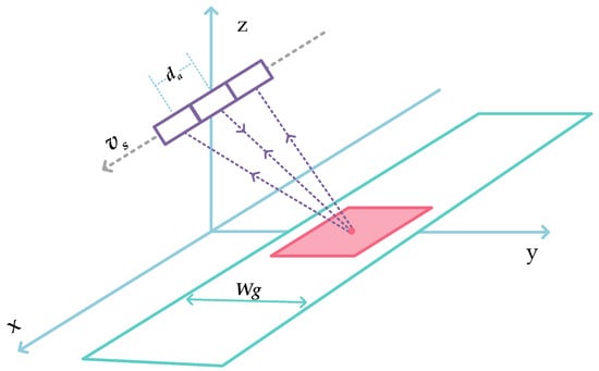
Figure 1.
The geometry of an azimuth MC-SAR system.
For each channel, the bistatic geometry can be converted into a monostatic one by compensating the radar echo with a constant phase term [20]. Hereafter, each channel is assumed to be located at its effective phase center (EPC). The coordinate of the th channel at azimuth time is , , and is the along-track distance between adjacent subapertures.
For MC-SAR systems, the low pulse repetition frequency is employed to avoid range ambiguities and is usually much lower than the instantaneous Doppler frequency, which results in the ambiguous Doppler spectrum. Suppose that there exist spectrum components coming from different directions, which implies that the Doppler ambiguity number is . Considering the pulsed operation of the spaceborne SAR, the Doppler spectrum of the echo can be expressed as:
where represents the channel phase bias between the th channel and the reference channel, denotes the range fast time, and represents the Doppler frequency.
For convenience, the signal of all receiving channels can be written in the form of the matrix, i.e.,:
where is the signal of all receiving channels in the range-Doppler domain, denotes the matrix of the channel phase bias, indicates the steering matrix of ambiguous components, and represents the signal matrix of the unambiguous single-channel signal in each frequency band.
where the subscript indicates that the signal channel phase bias exists, and represent the transpose and the diagonal matrix, respectively.
2.2. Modified Kurtosis
Kurtosis is a statistic related to the fourth-order central moment of a random variable, which describes the gradient of the distribution of all values of the variable. The expression is as follows:
where represents the mean value of a variable, and represents the variance of ; they can be expressed as:
The kurtosis emphasizes the degree of dispersion of the sequence value distribution relative to the sequence mean value. If the kurtosis is larger, the distribution of variable is sharper, and vice versa, as shown in Figure 2.
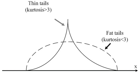
Figure 2.
Comparison chart of different kurtosis values.
The range alignment algorithm based on maximum kurtosis involves adding two echoes with the same envelope to form a new envelope. If the two echoes are aligned, the added envelope is sharper, and if the two echoes are misaligned, the added envelope is relatively flat, as shown in Figure 3. After practical tests, although the algorithm can align the echo data within a certain phase deviation, overall, sudden jumps occur from time to time. Therefore, the alignment results of this algorithm are not robust.
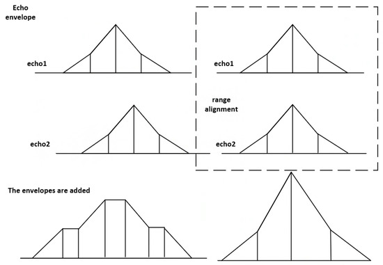
Figure 3.
Schematic diagram of the front and rear envelopes of target echo alignment.
The kurtosis has been modified to improve the sudden jumping situation. The modified kurtosis can be expressed as:
The difference between kurtosis and modified kurtosis is defined by variance. The variance is corrected according to the characteristics of echo data. It can reflect the degree of dispersion of the sequence numerical distribution with respect to the sequence mean and the main lobe of the beam. Modified kurtosis describes the echo alignment trend more accurately than kurtosis does, reflecting the actual alignment of the two echoes. Therefore, using MMK as a standard for range alignment is robust and accurate.
3. Channel Phase Bias Estimation Based on MMK
The azimuth spectrum of the echo data for each channel of the MC-SAR system is the same. The channel bias can cause the azimuth to shift into the spectrum. The azimuth spectrum of the th channel is added to the azimuth spectrum of the reference channel to obtain RDS. If the th channel has a channel bias, the spectral envelope will be offset, and the MK of the RDS will also change. Therefore, the estimation of the phase bias in the azimuth MC-SAR system is transformed into the MMK problem of optimizing the RDS. The flow chart of the proposed approach for the MC-SAR system is shown in Figure 4. The specific steps of the proposed approach are as follows.
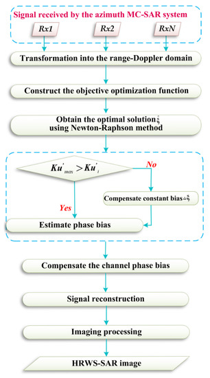
Figure 4.
The flow chart of the proposed approach.
3.1. Construction of the Objective Optimization Function
The echo received by each channel is subjected to an azimuth Fourier transform, and the azimuth spectrum of each channel and the azimuth spectrum of the reference channel are added to obtain the corresponding RDS. By analyzing the influence of the phase bias on MMK of RDS, the variation of the dispersion degree of the RDS envelope on MMK is described. The objective optimization function of the proposed approach can be expressed as:
where:
where represents the MMK, and can be written according to (2) as:
denotes the variance of the MMK. can be expressed as:
As can be seen from (17), the variance used in MMK is defined according to the dispersion degree of the sequence waveform. If the echo contains phase bias, the dispersion degree of the envelope is definitely higher than that of the corrected echo. If there is no phase bias in the echo, the MMK reaches its maximum value. The MMK describes the echo correction trend more accurately than MK does. Therefore, the MMK can better estimate the phase deviation between channels.
3.2. Estimation of Phase Bias
The objective optimization function is solved to obtain the phase bias estimation corresponding to the optimal MMK. The Newton–Raphson method is used to calculate the objective optimization function in (14). The estimated value of the th iteration can be expressed as:
where:
The iteration ends if , and the phase bias estimation of each channel relative to the reference channel can be obtained. The termination condition of the Newton–Raphson method is related to the estimation accuracy of the phase bias. This experiment sets the accuracy to three decimal places and stops iterating if the phase bias reaches this. Finally, the calculated phase bias estimate is used to compensate the phase of the received echo in the range-Doppler domain. Finally, an HRWS SAR image can be obtained after signal reconstruction and imaging processing. Since the proposed method operates in the range-Doppler domain, using the Chirp Scaling imaging algorithm is relatively simple.
4. Simulations and Real Data Processing
4.1. Simulated Results
In order to verify the accuracy of the phase bias estimation by the proposed method, a simulation experiment of three-point targets was carried out in this section. The simulation parameters are shown in Table 1. The number of channels is set to 3, and the channels from left to right in the azimuth direction are marked 1, 2, and 3, respectively, with channel 2 being set as the reference channel. The phase biases set in channel 1 and channel 3 are −25° and 25°, respectively. Figure 5a shows the azimuth profile of three targets after compression, where the green ellipse represents the real targets and the red ellipse represents the virtual targets. It can be obviously seen that there are virtual targets, caused by phase bias between channels. As shown in Figure 5b, the approach proposed in this paper can effectively suppress virtual targets, and the ambiguity component can be suppressed under −60 dB. As can be seen from Table 2, the estimated values of the phase errors of channel 1 and channel 3 are −24.869° and 25.153°, respectively, after processing by the proposed method. As shown by the green, purple, and pink lines in Figure 6, when there is a phase bias of −25° between channels, the maximum kurtosis, contrast, and entropy methods cannot accurately obtain the accurate channel phase bias estimation results. As shown by the red line, the proposed approach can accurately estimate the phase bias.

Table 1.
Simulation parameters.
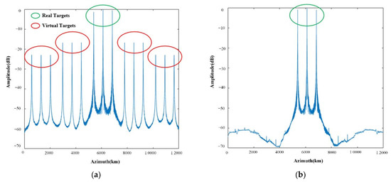
Figure 5.
(a) Azimuth profile with phase bias. (b) Azimuth profile after calibration.
Table 2.
Channel phase bias estimation results.
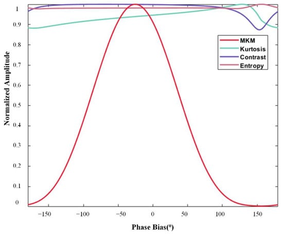
Figure 6.
Curves of MMK, kurtosis, contrast, and entropy with phase.
To verify the robustness of the proposed approach, the averaged root-mean-square error (ARMSE) of channel phase biases is used to evaluate the influence of the proposed approach under different SNRs by using the Monte Carlo method. Figure 7a shows the ARMSE of the cross-correlation method (CCM), signal subspace comparison method (SSCM) [13], and proposed method with different SNRs. The phase bias estimation performance of the three methods is equivalent to a high SNR. However, compared with CCM and SSCM, the proposed approach shows a better estimation performance than the CCM and SSCM methods in a low SNR. Figure 7b shows the ARMSE curves of the three methods under different channel uniformity values. It can be seen that the more uniform the channel is, the higher the estimation performance of the proposed approach.
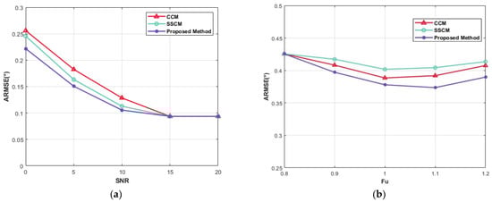
Figure 7.
(a) ARMSEs of phase bias estimates versus SNR: CCM (red), SSCM (green), the proposed approach (purple). (b) ARMSEs of phase bias estimates versus channel uniformity: CCM (red), SSCM (green), the proposed approach (purple).
4.2. Real Data Processing
In this part, the real azimuth MC-SAR data is used to verify the effectiveness of the proposed approach. Table 3 shows the parameters of an actual C-band airborne azimuth stripmap MC-SAR system. Figure 8 shows the imaging results of the MC-SAR data, where the green ellipse represents the real targets and the red ellipse represents the virtual target caused by the channel phase bias. For the real targets, the ratio of the maximum power points in the virtual target area to that of the real target area is recorded and denoted as . The maximum virtual target power (MVTP) is defined as . Figure 8a is a SAR image processed without phase bias calibration, and it is obvious that the SAR image quality is severely degraded. Table 4 shows the MVTP. Figure 8b is a SAR image processed with calibration using the CCM. Compared with Figure 8a, the MVTP in Figure 8b can be suppressed beneath −32.12 dB. The imaging quality has improved to a certain extent, but virtual targets with strong scattering points within the red ellipse were not suppressed. Figure 8c is a SAR image processed with calibration using the proposed approach. The MVTP can be suppressed beneath −43.56 dB. Compared with CCM, the virtual targets with strong scattering points within the red ellipse are suppressed, and the SAR imaging quality is further improved. Thus, the effectiveness of the proposed method is verified.
Table 3.
Main parameters of real airborne data.
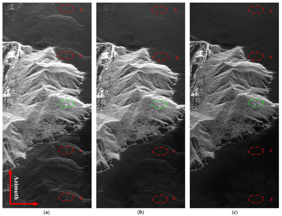
Figure 8.
Focused SAR image. (a) SAR image processed without phase bias calibration. (b) SAR image processed with calibration using the CCM. (c) SAR image processed with calibration using the proposed approach.
Table 4.
Maximum virtual target power.
5. Conclusions
The existence of channel phase bias seriously affects the imaging quality of SAR signals. However, most existing methods have an unstable performance in the case of low SNR and channel non-uniformity. To solve this problem, this paper analyzes the influence of channel phase bias on each channel and proposes a robust channel phase bias correction method based on a modified kurtosis theory.
In the proposed method, the phase bias estimation problem is transformed into an MMK estimation problem for optimizing RDS and establishes the objective optimization function. This function is solved using the Newton−Raphson method. In order to verify the robustness of the proposed method, simulation experiments were carried out under different SNRs and different channel non-uniformities. The ARMSE of the channel error shows that the proposed method can estimate the channel phase bias more accurately than CCM and SSCM, which demonstrates the robustness of the proposed method. In order to verify the effectiveness of the proposed method, real data experiments were carried out. The MVTP results show that the proposed method suppresses the false target energy by at least 10 dB compared with CCM, which verifies its effectiveness. However, the proposed method has an iterative process resulting in a high time complexity, and the time complexity optimization of the proposed method will be the focus of our next work.
Author Contributions
Analysis, X.P. and H.Z.; methodology, X.P., H.Z. and G.S.; validation, X.P., H.Z. and G.S.; resources, X.P., H.Z. and G.S.; writing—original draft preparation, X.P. and H.Z.; writing—review and editing, G.S. and H.Z. All authors have read and agreed to the published version of the manuscript.
Funding
This work was supported in part by the National Natural Science Foundation of Henan under Grant number 222300420115, and in part by the Foundation of Key Laboratory of Radar Imaging and Microwave Photonics, Ministry of Education under Grant RIMP2020003.
Acknowledgments
Thanks to all anonymous reviewers and editors for their comments and suggestions, making this article’s content more rigorous and meaningful.
Conflicts of Interest
The authors declare no conflict of interest.
References
- Freeman, A.; Johnson, W.T.K.; Huneycutt, B.; Jordan, R.; Hensley, S.; Siqueira, P. The “Myth” of the minimum SAR antenna area constraint. IEEE Trans. Geosci. Remote Sens. 2000, 38, 320–324. [Google Scholar] [CrossRef]
- Krieger, G.; Moreira, A.; Fiedler, H.; Hajnsek, I.; Werner, M.; Younis, M.; Zink, M. TanDEM-X: A Satellite Formation for High-Resolution SAR Interferometry. IEEE Trans. Geosci. Remote Sens. 2007, 45, 3317–3341. [Google Scholar] [CrossRef]
- Li, N.; Shen, Q.; Wang, L.; Wang, Q.; Guo, Z.; Zhao, J. Optimal Time Selection for ISAR Imaging of Ship Targets Based on Time-Frequency Analysis of Multiple Scatterers. IEEE Geosci. Remote Sens. Lett. 2022, 19, 1–5. [Google Scholar] [CrossRef]
- Wang, R.; Loffeld, O.; Neo, Y.; Nies, H.; Walterscheid, I.; Espeter, T.; Klare, J.; Ender, J. Focusing Bistatic SAR Data in Airborne/Stationary Configuration. IEEE Trans. Geosci. Remote Sens. 2010, 48, 452–465. [Google Scholar] [CrossRef]
- Krieger, G.; Gebert, N.; Moreira, A. Unambiguous SAR signal reconstruction from nonuniform displaced phase center sampling. IEEE Geosci. Remote Sens. Lett. 2004, 1, 260–264. [Google Scholar] [CrossRef]
- Li, Z.; Wang, H.; Su, T.; Bao, Z. Generation of wide-swath and high-resolution SAR images from multichannel small spaceborne SAR systems. IEEE Geosci. Remote Sens. Lett. 2005, 2, 82–86. [Google Scholar] [CrossRef]
- Gebert, N.; Krieger, G.; Moreira, A. Digital Beamforming on Receive: Techniques and Optimization Strategies for High-Resolution Wide-Swath SAR Imaging. IEEE Trans. Aerosp. Electron. Syst. 2009, 45, 564–592. [Google Scholar] [CrossRef]
- Zhang, S.; Xing, M.; Xia, X.; Liu, Y.; Guo, R.; Bao, Z. A Robust Channel-Calibration Algorithm for Multi-Channel in Azimuth HRWS SAR Imaging Based on Local Maximum-Likelihood Weighted Minimum Entropy. IEEE Trans. Image Process. 2013, 22, 5294–5305. [Google Scholar] [CrossRef] [PubMed]
- Kim, J.; Younis, M.; Prats-Iraola, P.; Gabele, M.; Krieger, G. First Spaceborne Demonstration of Digital Beamforming for Azimuth Ambiguity Suppression. IEEE Trans. Geosci. Remote Sens. 2013, 51, 579–590. [Google Scholar] [CrossRef]
- Zhang, S.; Xing, M.; Xia, X.; Zhang, L.; Guo, R.; Lian, Y.; Bao, Z. Multichannel HRWS SAR Imaging Based on Range-Variant Channel Calibration and Multi-Doppler-Direction Restriction Ambiguity Suppression. IEEE Trans. Geosci. Remote Sens. 2014, 52, 4306–4327. [Google Scholar] [CrossRef]
- Zhang, S.; Xing, M. A Novel Doppler Chirp Rate and Baseline Estimation Approach in the Time Domain Based on Weighted Local Maximum-Likelihood for an MC-HRWS SAR System. IEEE Geosci. Remote Sens. Lett. 2017, 14, 299–303. [Google Scholar] [CrossRef]
- Feng, J.; Gao, C.; Zhang, Y.; Wang, R. Phase Mismatch Calibration of the Multichannel SAR Based on Azimuth Cross Correlation. IEEE Geosci. Remote Sens. Lett. 2013, 10, 903–907. [Google Scholar] [CrossRef]
- Liu, Y.; Li, Z.; Wang, Z.; Bao, Z. On the Baseband Doppler Centroid Estimation for Multichannel HRWS SAR Imaging. IEEE Geosci. Remote Sens. Lett. 2014, 12, 2050–2054. [Google Scholar]
- Zhang, L.; Xing, M.; Qiu, C.; Bao, Z. Adaptive two-step calibration for high-resolution and wide-swath SAR imaging. IET Radar Sonar Navig. 2010, 4, 548–559. [Google Scholar] [CrossRef]
- Yang, T.; Li, Z.; Liu, Y.; Bao, Z. Channel Error Estimation Methods for Multichannel SAR Systems in Azimuth. IEEE Geosci. Remote Sens. Lett. 2013, 10, 548–552. [Google Scholar] [CrossRef]
- Zhao, J.; Wang, K.; Wang, L.; Guo, Z.; Li, N. A novel phase bias estimation method for multichannel HRWS SAR system in azimuth based on RDS analysis. Remote Sens. Lett. 2020, 12, 42–50. [Google Scholar] [CrossRef]
- Sun, G.; Xiang, J.; Xing, M.; Yang, J.; Guo, L. A channel phase error correction method based on joint quality function of GF-3 SAR dual-channel images. Sensors 2018, 18, 3131. [Google Scholar] [CrossRef]
- Cai, Y.; Deng, Y.; Zhang, H.; Wang, R.; Wu, Y.; Cheng, S. An Image-Domain Least L 1-Norm Method for Channel Error Effect Analysis and Calibration of Azimuth Multi-Channel SAR. IEEE Trans. Geosci. Remote Sens. 2022, 60, 1–14. [Google Scholar] [CrossRef]
- Wang, L.; Zhu, Z. New Range Alignment Algorithm for ISAR Based on Maximum Modified Kurtosis. J. Nanjing Univ. Aeronaut. Astronaut. 2006, 38, 722–726. [Google Scholar]
- Given, J.A.; Schmidt, W.R. Generalized ISAR—part I: An optimal method for imaging large naval vessels. IEEE Trans. Image Process. 2005, 14, 1783–1791. [Google Scholar] [CrossRef] [PubMed]


Publisher’s Note: MDPI stays neutral with regard to jurisdictional claims in published maps and institutional affiliations. |
© 2022 by the authors. Licensee MDPI, Basel, Switzerland. This article is an open access article distributed under the terms and conditions of the Creative Commons Attribution (CC BY) license (https://creativecommons.org/licenses/by/4.0/).