Article

A Scalable Montgomery Modular Multiplication Architecture with Low Area-Time Product Based on Redundant Binary Representation

School of Micro-Nano Electronics, Zhejiang University, Hangzhou 310058, China
*
Author to whom correspondence should be addressed.
Electronics 2022, 11(22), 3712; https://doi.org/10.3390/electronics11223712
Submission received: 19 October 2022 / Revised: 3 November 2022 / Accepted: 7 November 2022 / Published: 13 November 2022
(This article belongs to the Section Electronic Materials)

Abstract

:
The Montgomery modular multiplication is an integral operation unit in the public key cryptographic algorithm system. Previous work achieved good performance at low input widths by combining Redundant Binary Representation (RBR) with Montgomery modular multiplication, but it is difficult to strike a good balance between area and time as input bit widths increase. To solve this problem, based on the redundant Montgomery modular multiplication, in this paper, we propose a flexible and pipeline hardware implementation of the Montgomery modular multiplication. Our proposed structure guarantees a single-cycle delay between two-stage pipeline units and reduces the length of the critical path by redistributing the data paths between the pipelines and preprocessing the input in the loop. By analyzing the structure and comparing the related work in this paper, our structure ensures a lower area-time product while achieving a controllable and small area consumption. The comprehensive results under different Taiwan Semiconductor Manufacturing Company (TSMC) processes demonstrate the advantages of our structure in terms of flexibility and area-time product.

1. Introduction

Many public key cryptosystems such as Rivest–Shamir–Adleman (RSA), elliptic curve cryptography (ECC), and sm9 require a lot of modular multiplication. Conventional modular multiplication is an expensive operation, as it requires division; this would take a lot of time and space to implement in hardware. What’s more, for RSA, some operands can even reach 8192 bits, which means there is no suitable solution for traditional modulo multiplication methods. To solve this problem, Montgomery Modular Multiplication (MMM) [1] has been raised, which is an efficient method for calculating large integer modular multiplication by replacing the modular operation with a simple shift operation for hardware systems.
Several efforts have been made to optimize MMM’s hardware implementation. Some papers mainly focus on using different multiplication algorithms such as the Karatsuba multiplier [2] or the Toom–Cook multiplier [3], which will lead to a high-performance word-based MMM design. Fast Fourier Transform (FFT) [4], Residue Number System (RNS) [5], and Non-least Positive Form [2] are also introduced for accelerating. Meanwhile, others tend to trade off between performance and area as when giving a large input width, it will cause an extremely high cost in hardware. Digital-serial implementations are proposed using high radix MMM, such as a radix-4 architecture using lookup tables [6] or booth encoding [7]. Radix-8 architecture uses booth encoding [8] and typically improves schemes based on carry-save adder (CSA) for the radix-2 system [9,10]. Some optimization has also been made on the CSA architecture [11,12,13]. However, many implementations for a low area cost have problems with their long carry chains, which will highly impact the performance of MMM. Although several high-performance adders such as the Kogge–Stone adder [14], carry-skip adder [15], carry-select adder [16], and Reverse Carry Propagate adder [17] are trying to solve this problem, they either have a higher demand for area or cannot meet all radix requirements. Some optimization [18,19] are made in achieving one-cycle latency pipeline word-based MMM by rearranging the basic pipeline algorithm in [20], but they do not change the basic algorithm’s iteration and pay much effort on scheduling. In that case, Ref. [21] has proposed a Redundant Binary Representation MMM (RBR-MMM) algorithm to solve the carry-chain problem by bringing the operations of MMM into the redundant system, which successfully eliminates the long carry chain and improves the performance of MMM.
Although the RBR-MMM method reaches a balance of performance and cost when the input width is 256 bits or 1024 bits, there will be an enormous area cost when the input width becomes large as a reason for RBR-MMM’s parallel design, which costs a large number of multipliers. RBR-MMM’s critical path delay is mainly dependent on the k parameter, typically when k is small; this design can reach a high frequency, but for advanced technology to reach a low latency, we always choose to have a larger optimized multiplier, so the RBR-MMM’s ‘ATP’ (Area-Time Product) ( k G a t e s μ s ) will be unacceptable. Moreover, its high memory bandwidth requirement problem along with high bit width input is critical.
To solve the RBR-MMM’s problem, in this paper, we first propose a hardware suitable pipeline RBR-MMM (PRBR-MMM) to lessen the high area cost when the input width is large. Then, we optimized the RBR-MMM to reach a one-cycle delay between two pipeline stages. Finally, we take the critical path in each stage in two paths and precalculate the first path by using our pipeline buffer, and this leads to an almost 2/3 critical path compared with basic RBR-MMM, which will make up for a large part of the delay caused by the pipeline. As a result, our pipeline previous calculated RBR-MMM design (PPCRBR-MMM) has the following features:
  • Low and customizable area cost: our area cost is mainly affected by the pipeline-stage-num. When using a memory outside our module, area cost will be lower by storing the temporary result outside.
  • Small critical path: our critical path is smaller by cutting calculating into precalculate quotient logic and multiplication-shift logic.
  • Low memory bandwidth requirement: compared with RBR-MMM, which needs whole operators simultaneously, our design only needs two words every cycle and only writes one word out. The word size is determined by the multiplier used in our design.
  • Low and customizable latency: we adapt the algorithm to the pipeline to prevent the 2-cycle delay between each stage. Latency will be determined by the stage num and input width.

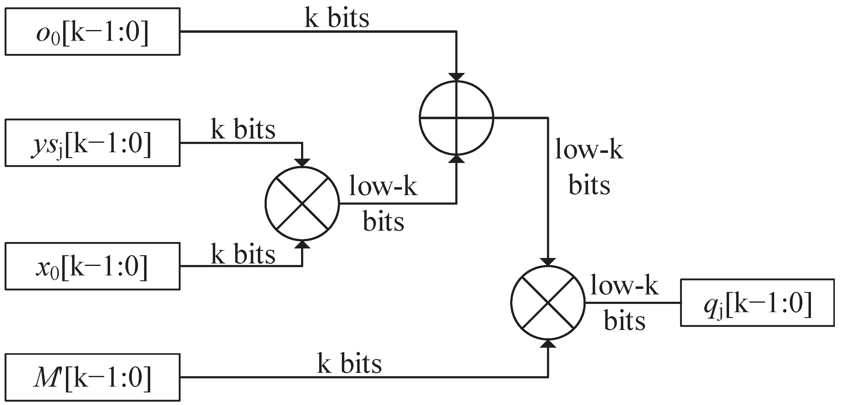
2. Algorithm Fundamentals

A redundant binary representation is a numeral system that uses more bits than needed to represent a single binary digit. In that case, an RBR allows addition without using a typical carry, which will prevent the long carry-chain in MMM system [16]. What is more, different from another redundant system-RNS [5], RBR is easy to covert from normal representation, making MMM’s operand’s translation simple. A typical 2 2 k RBR number X with its component x i can be expressed as (1).
X = i = 0 n 1 x i · 2 2 k i , x i { 0 , 1 , , 2 2 k + 1 1 } ;
When changing a simple operand into the above-mentioned system, we only need to divide data into 2 k bits and let the Most Significant Bit (MSB) be zero. The RBR-MMM takes the above-mentioned expression into the MMM system and prevents the transformation between redundant numbers and nonredundant numbers during the iteration. As many public-key systems call MMM several times, only one additional cycle for transformation is needed to get the final result. The RBR-MMM algorithm is described in Algorithm 1. By representing the operands in the calculation process with redundant bases, RBR-MMM makes the carry in the algorithm iteration process directly stored in the intermediate result without additional conversion. At the same time, because o itself is also a redundant binary representation, no extra carry is generated in the process of calculating o for each iteration. The carry propagation problem in modular multiplication is solved by converting the carry into a redundant number. The proof of Algorithm 1 has been provided by [21]; we only discuss its critical path and area consumption in this paper.
Algorithm 1 Basic Radix- 2 k RBR-MMM ( k 2 ).
INPUT: X , Y , M , M ; 0 X , Y 2 M ;
  M is prime; X,Y,M are in RBR:
   X = i = 0 n 1 x i · 2 2 k i , x i { 0 , 1 , , 2 2 k + 1 1 } ;
   Y = i = 0 n 1 y i · 2 2 k i , y i { 0 , 1 , , 2 2 k + 1 1 } ;
   M = i = 0 n 1 m i · 2 2 k i , m i { 0 , 1 , , 2 2 k 1 } ;
   M [ k 1 : 0 ] = M 1 m o d 2 k ;
OUTPUT: O = X Y 2 2 k n m o d M ; 0 O 2 M ;
 1:  O = 0 , O = 0 ;
    O = i = 0 n 1 o i · 2 2 k i , o i { 0 , 1 , , 2 2 k + 1 1 } ;
    O = i = 0 n 1 o i · 2 2 k i , o i { 0 , 1 , , 2 3 k + 2 1 } ;
 2:  y s 1 = y 0 [ 2 k 1 : k ] , y s 0 = y 0 [ k 1 : 0 ] , y c 0 = y _ s 0 [ 2 k ] ;
    o 1 = 0 , o n = 0 ;
 3: for j = 0 to 2 n 1 do
 4:     o = o 0 m o d 2 k ;
 5:     x = x 0 m o d 2 k ;
      //computing quotient logic
 6:     q j = ( ( ( o + y s j · x ) m o d 2 k ) · M ) m o d 2 k ;
      //parallel computing o’
 7:    for i = 0 to n 1 do
 8:      o i = ( o i + y s j · x i + q j · m i ) ;
 9:    end for
      //parallel computing shift right logic to cal new_o
 10:    for i = 0 to n 1 do
 11:       o i = o i 1 [ 3 k + 1 : 3 k ] + o i [ 3 k 1 : k ] + o i + 1 [ k 1 : 0 ] k ;
 12:    end for
      //convert y to binary representation
 13:    if j % 2 = = 1 do
 14:      { y c j + 1 2 , y s j + 2 , y s j + 1 } = y j + 1 2 + y c j 1 2 ;
 15:   end if
 16: end for
 17: return O
In Algorithm 1, M is precalculated for the reason that MMM will be called several times using the same M, so there is no need for us to calculate M in our algorithm; n should be an integer that is determined by M. Usually, we take n as n = [ m + 2 2 k ] + 1 , where m bits is the bit width of M. Thus, we can get that the cycles for hardware to do a single RBR-MMM with the precalculated M can be expressed as (2), which is determined by the k value.
l o o p = 2 · [ m + 2 2 k ] + 2 ;
Meanwhile, we can get RBR-MMM’s critical path by reviewing the main operands in Algorithm 1, take computing quotient logic as an example. From Figure 1, we can see that the max delay is created by two k bits multipliers and a half adder; thus, its path is rough ( 3 k + 2 [ k 3 ] ) · T F A , where T F A is the delay of a full adder, we can quickly get a full critical path in (3). Finally, let us look at the RBR-MMM’s area consumption: for computing quotient logic, there will be about two k bits multipliers and one k bits adder used as computing quotient is needed one time for j-loop. However, for parallel computing s and shift right part, nk bits × 2 k bits multipliers, k bits × 2 k + 1 bits multipliers, 3 k + 1 bits full adder, and 2 k bits adder are demanded.
T t o t a l = ( ( 3 k + 2 [ k 3 ] ) + ( 2 k ) + ( 3 k + 2 + [ 2 k + 1 3 ] ) ) · T F A ( 10 k + 3 ) · T F A ;
It can be seen from the above analysis that the critical path length of RBR-MMM is only related to the k value. This means that in the case of low input bit width, the parallelized RBR-MMM algorithm can achieve better frequency and lower area through lower k. In the case of high input bit width, the algorithm can also meet higher frequency requirements through a lower k value. When input bits are high, which generally occurs for RSA in high-speed encrypt system, area cost of RBR-MMM will not be decreased due to its parallel implementation. If high speed is needed, there may not be several 2 k bits multipliers for this unit to use. Another problem is that there will be more additional cycles for RBR-MMM to read its input and write its output back to memory, so an area scalable structure to prevent high cost and keep a good ATP is recommended, which leads us to mix the typical pipeline design with RBR-MMM. Our PPCRBR-MMM system will be discussed in the next section.

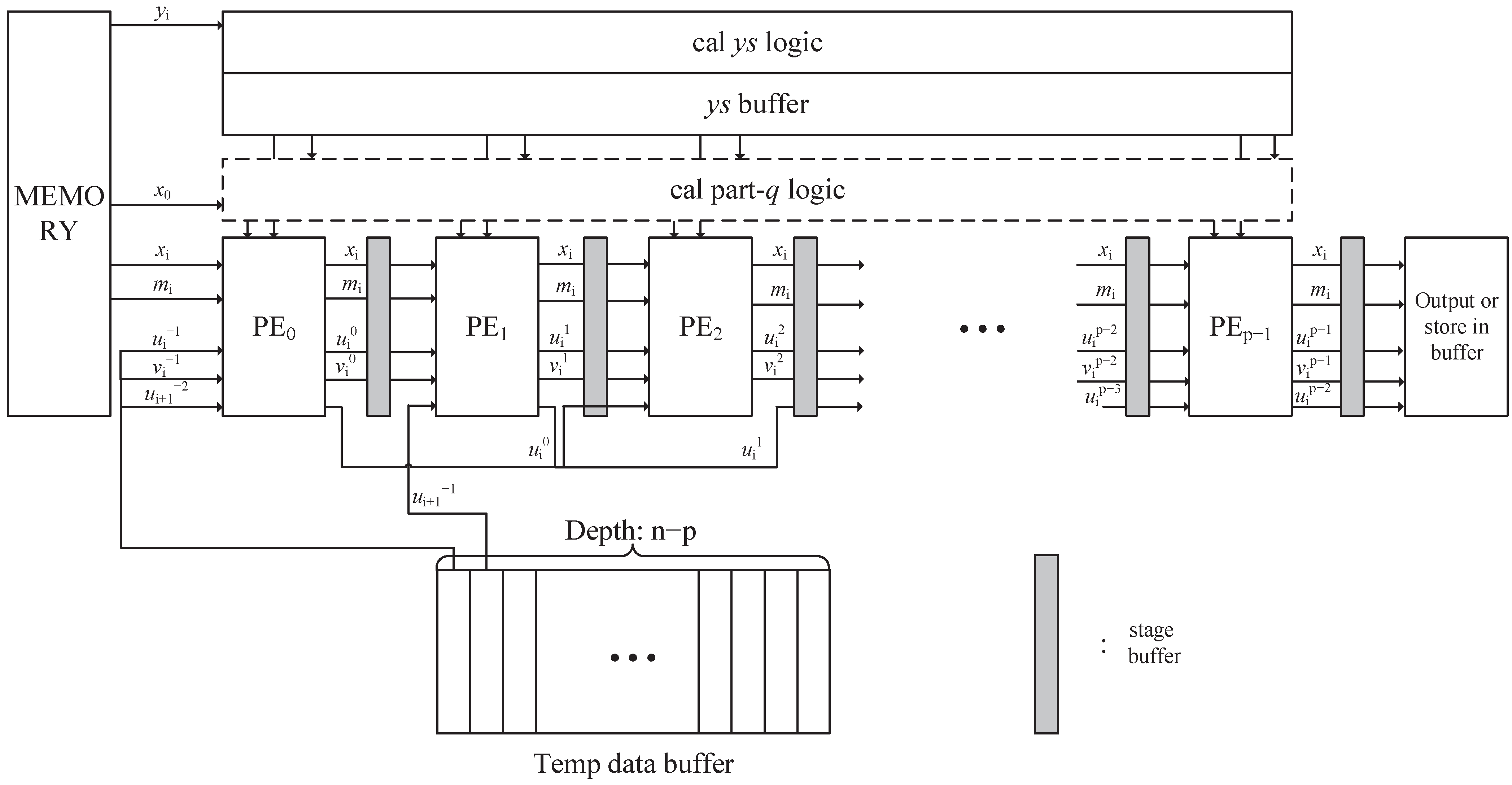
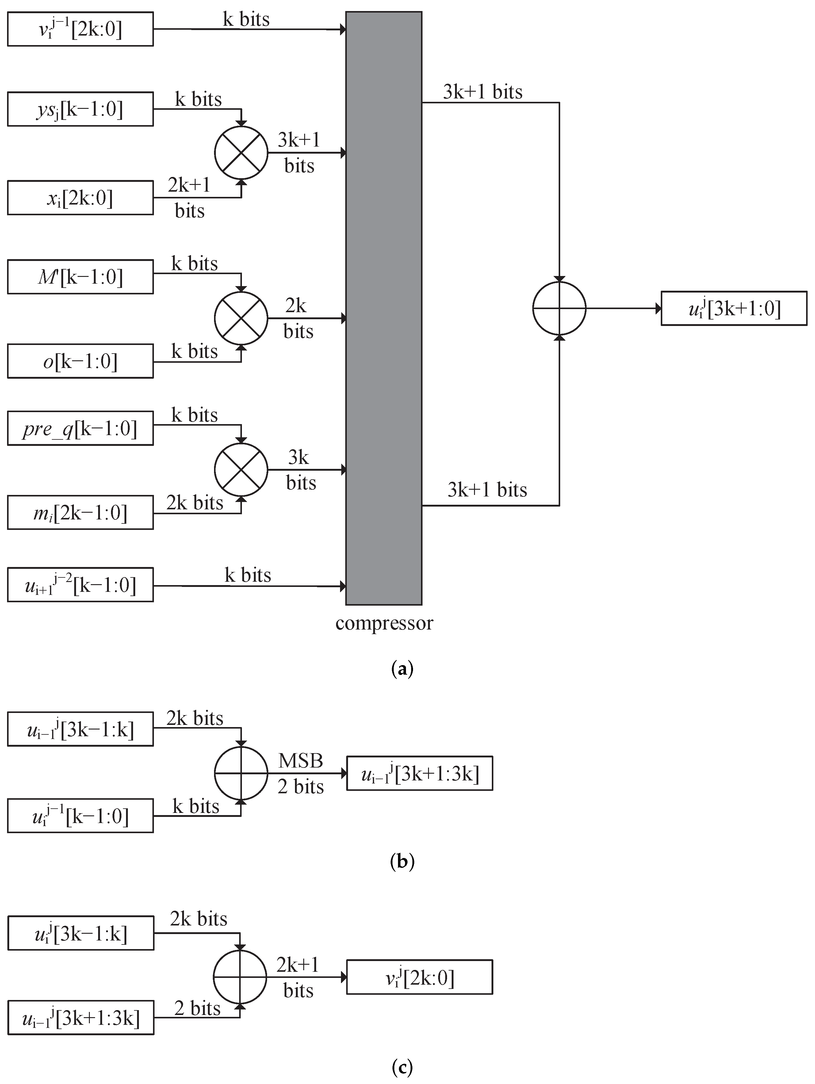
3. Pipeline Precalculate Redundant Binary Representation Montgomery Modular Multiplication

According to the analysis mentioned in the previous section, a typical pipeline MMM [20] is needed to get a better performance in ATP. However, when we go through the parallel computing in RBR-MMM, we can find that its hard for us to implement a fully pipeline RBR-MMM as a reason of the high dependency between the j = n and j = n + 1 loop, which is explained as: for a new o i , both o i + 1 and o i is needed, which will cost two cycles for a typical pipeline design. So, we rearrange the algorithm to adapt to a pipeline design with one cycle delay between two stages. Then for computing quotient logic, we split it with parallel computing, as q will not be changed for the same j loop, and consuming one more cycle will lead to a shorter critical path. This splitting has another advantage: when a buffer is needed to temporary storage the last stage’s result, we can call pre-q logic to do computing quotient logic without an additional cycle; this will be discussed later. Our PPCRBR-MMM can be described as Algorithm 2.
Algorithm 2 Basic Radix- 2 k PPCRBR-MMM ( k 2 ).
INPUT: X , Y , M , M ; 0 X , Y 2 M ;
  M is prime; X,Y,M are in RBR:
   X = i = 0 n 1 x i · 2 2 k i , x i { 0 , 1 , , 2 2 k + 1 1 } ;
   Y = i = 0 n 1 y i · 2 2 k i , y i { 0 , 1 , , 2 2 k + 1 1 } ;
   M = i = 0 n 1 m i · 2 2 k i , m i { 0 , 1 , , 2 2 k 1 } ;
   M [ k 1 : 0 ] = M 1 m o d 2 k ;
OUTPUT: O = X Y 2 2 k n m o d M ; 0 O 2 M ;
 1:  O j = 0 , V j = 0 , U j = 0 ;
    O j = i = 0 n 1 o i j · 2 2 k i , o i j { 0 , 1 , , 2 2 k + 1 1 } ;
    U j = i = 0 n 1 u i j · 2 2 k i , u i j { 0 , 1 , , 2 3 k + 2 1 } ;
    V j = i = 0 n 1 v i j · 2 2 k i , v i j { 0 , 1 , , 2 2 k + 1 1 } ;
 2:  y s 1 = y 0 [ 2 k 1 : k ] , y s 0 = y 0 [ k 1 : 0 ] , y c 0 = y _ s 0 [ 2 k ] ;
    u 1 j = 0 , u n j = 0 , u i 1 = 0 , u i 2 = 0 , v i 1 = 0 ;
   // totally 2n iteration, each j means one pipeline stage
 3: for j = 0 to 2 n 1 do
 4:   o = ( v 0 j 1 + u 1 j 2 [ k 1 : 0 ] ) m o d 2 k ;
 5:   x = x 0 m o d 2 k ;
    //computing quotient logic
 6:   p r e _ q j = ( ( ( y s j · x ) m o d 2 k ) · M ) m o d 2 k ;
    //inner-loop: for each pipeline, n cycles are needed
 7:  for i = 0 to n 1 do
 8:      u i j = ( v i j 1 + u i + 1 j 2 [ k 1 : 0 ] + y s j · x i + p r e _ q j · m i + o · M m o d 2 k ) ;
 9:      u i 1 j [ 3 k + 1 : 3 k ] = M S B ( u i j 1 [ k 1 : 0 ] + u i 1 j [ 3 k 1 : k ] ) ;
 10:     v i j = u i 1 j [ 3 k + 1 : 3 k ] + u i j [ 3 k 1 : k ] ;
 11:  end for
    //convert y to binary representation
 12:  if j % 2 = = 1 do
 13:    { y c j + 1 2 , y s j + 2 , y s j + 1 } = y j + 1 2 + y c j 1 2 ;
 14:  end if
 15: end for
 16: //two more cycles are needed for output
 17: for i = 0 to n 1 do
 18:   o i 2 n 1 = v i 2 n 1 + u i + 1 2 n 2 [ k 1 : 0 ] + u i + 1 2 n 1 [ k 1 : 0 ] k
 19: end for
 20: return O
Typical pipeline design often goes with a problem in carrying. In RBR-MMM, it occurs between two adjacent j-loop. Let the j-th pipeline-stage out and temp out be o i j and o i j ,we can get (4).
o i j = o i j 1 + y s j · x i + q j · m i ; o i j = o i 1 j [ 3 k + 1 : 3 k ] + o i j [ 3 k 1 : k ] + o i + 1 j [ k 1 : 0 ] k ;
In this equation, every o i j needs o i j 1 ’s result, which needs both o i j 1 and o i + 1 j 1 to solve out, so there will be a two cycles delay between the pipeline stage, thus we consider rearranging our algorithm by changing the o i + 1 j 1 to the next cycle. We first ignore the o i + 1 j 1   k to calculate o i j 1 , let our output be new(output), we can get (5)
n e w ( o i j ) = o i j o i + 1 j [ k 1 : 0 ] k ; n e w ( o i j ) = o i j o i + 1 j 1 [ k 1 : 0 ] k ;
Ingeniously, our q calculating will be the same due to this lack of addition will only affect the high k + 1 bits of o i j 1 , then we only need to consider the o i j ’s lack of o i + 1 j 1 . From (4) and (5), the temp result can be calculated as (6) and (7).
n e w ( o i j + 1 ) = o i j + y s j + 1 · x i + q j + 1 · m i o i + 1 j [ k 1 : 0 ] k ; = n e w ( o i j ) + y s j + 1 · x i + q j + 1 · m i ;
n e w ( o i j + 1 ) = { n e w ( o i 1 j + 1 ) + o i j [ k 1 : 0 ] k } [ 3 k + 1 : 3 k ] + n e w ( o i j + 1 [ 3 k 1 : k ] ) + o i + 1 j [ k 1 : 0 ] + o i + 1 j + 1 [ k 1 : 0 ] k o i + 1 j + 1 [ k 1 : 0 ] k ; = { n e w ( o i 1 j + 1 ) + n e w ( o i j ) [ k 1 : 0 ] k } [ 3 k + 1 : 3 k ] + n e w ( o i j + 1 [ 3 k 1 : k ] ) + n e w ( o i + 1 j ) [ k 1 : 0 ] ;
In order to avoid dependencies on the upper-level unit, we transfer the addition of n e w ( o i + 1 j ) [ k 1 : 0 ] to the calculation of the next-level unit. Let u i j = n e w ( o i j ) and v i j = n e w ( o i j ) n e w ( o i + 1 j 1 ) [ k 1 : 0 ] . Finally, we can get that the output of the next stage should be computed as (8)
u i j + 1 = v i j + y s j + 1 · x i + q j + 1 · m i + u i + 1 j 1 [ k 1 : 0 ] ; u i 1 j + 1 [ 3 k + 1 : 3 k ] = M S B ( u i j [ k 1 : 0 ] + u i 1 j + 1 [ 3 k 1 : k ] ) ; v i j + 1 = u i 1 j + 1 [ 3 k + 1 : 3 k ] + u i j + 1 [ 3 k 1 : k ] ;
From (8), only one cycle’s previous stage’s result is needed to get a new output with an additional add operation of the output of the first two stages; thus, we can build up a single cycle delay pipeline RBR-MMM design. Meanwhile, to prevent a long critical path when k is large, we precalculate the quotient or part of the quotient in the first cycle of each stage, which only costs one more cycle for a pipeline design. Then, we get our Algorithm 2: PPCRBR-MMM.
According to Algorithm 2, an RBR-MMM-based pipeline architecture is proposed in this brief, which will get a better ATP than RBR-MMM. Our algorithm’s hardware implementation consists of several processing elements (PEs), pre-calculate quotient units, data registers, and fewer control logics. To clarify our structure, a dependency graph is delivered as Figure 2, and each Q job calculates pre_q value in Algorithm 2, the inner loop is done by I job. By rearranging the RBR-MMM algorithm’s data chain, our PE can work out its result just with the output of the last cycle, total three inputs from left PE and left of left PE and PE self are needed. For each PE’s first cycle, the quotient will be calculated, costing only one more cycle delay than before.
Figure 3 shows a block diagram of our pipeline RBR-MMM. The kernel part consists of pk-param PEs. Each PE contains (8)’s logic and some registers to hold input value and temp result. For common and low-area usage, p will often be lower than n, which means some PE-unit will do more than one loop calculation. Thus, the PE p will compute out before PE 1 has finished n-cycle computation, and the output must be queued in a buffer before PE1 becomes available again. The buffer depth is determined by n p and its width is defined as 2 k + 1 (the v i j ’s width) + k (the u i j [ k 1 : 0 ] ’s width) + k (the u i + 1 j 1 [ k 1 : 0 ] ’s width) + 2 k (the m i ’s width) + 2 k + 1 (the x i ’s width), this buffer will be an inevitable but acceptable cost compared with basic RBR-MMM design, and this register cost can be transferred to memory outside if needed. Furthermore, quotient value can also be pre-calculated in our buffer. In that case, o · M m o d 2 k part is not needed in (8) (as that optimization will have no effect on our frequency and to keep our equation easy, we still do this part in our design), and no more cycle is needed. Other parts of our block are some control logic, select logic of buffer, final output, and y s storage.

4. Analysis of PPCRBR-MMM

In this section, a critical path, area, and cycle analysis of PPCRBR-MMM is proposed for comparison with basic RBR-MMM implementation.

4.1. Timing Analysis

Typically, we take p smaller than n to prevent a high-cost design, and then from Figure 4, each PE unit takes n + 1 cycles to compute its first loop result. Total 2 n loops are needed to solve out final O from Algorithm 2, thus we can get that [ 2 n / p ] inner-loops are needed for PE0-PE(2n%p), and for the final loop, 2 n % p + n + 2 1 cycles are required. Finally, we get Equation (9).
l o o p = [ 2 n / p ] · n + 2 + 2 n % p + n ;
In comparison with (2),we can get a cycle_ratio in (10). Previously, we have mentioned that the whole operand cannot be read or written only in one cycle, which will also inevitably impact basic RBR-MMM. Thus the loop_ratio will be smaller than (10) in hardware design.
l o o p _ r a t i o = ( [ 2 n / p ] · n + 2 + 2 n % p + n ) / 2 n = [ 2 n / p ] + 1 2 + 2 n % p + 2 2 n ;

4.2. Critical Path Analysis

To better understand our path delay and area cost, a detailed circuit schematic is illustrated in Figure 5, the partial computing output O i circuit consists of k × 2 k , k × ( 2 k + 1 ) , k × k multipliers which are independent, thus they can fuse to addition using CSA (i.e., 4:2 compressor), to simplify our delay calculate, we let this part of critical path be a k × 2 k + 1 bits multiplier’s half adders’ path with 7:2 compressors and 3 k + 1 Carry Propagate Adder (CPA), o · M and calculate o part can be broken into 4:2 compressor. The MSB of u i 1 j will be calculated simultaneously and will have no impact on our critical path. At last, we take a 2 k bits carry propagation adder to solve the v i j out. Thus we can get our critical path will be (11)
T t o t a l = ( 2 k ) + ( 3 k + 1 + 2 + 2 k + 1 3 ) · T F A ( 6 k + 3 ) · T F A ;
Obviously, pre-calculate quotient logic lets our critical path decreases; this ratio can be expressed as (12)
p a t h _ r a t i o = ( 6 k + 3 ) · T F A / ( 10 k + 3 ) · T F A 3 5 ;

4.3. Area Analysis

For area analysis, we mainly focus on the area cost for single PE compared with the parallel computation module in the RBR-MMM system. From Figure 5, we can summarize a rough area cost for single PE: one 2 k bits carry propagation adder for v i j , one 3 k + 2 carry propagation adder, 5 k 2 + k ‘AND’ Gates and some compressors for u i j and one calculate carry bit logic for the MSB. The last one can be implemented by k ‘AND’ Gates and a k bits adder. We can see that our additional logic will not consume much more area for single PE.
Obviously, considering area cost, our PE’s number will not be large; in that case, high area cost will be eliminated for a large input case. For intuitive explanation, if we take p = n / 2 , we can get a roughly ATP ratio shown in (13); Clearly, our PPCRBR-MMM design will lead to a better ATP as area_ratio will be nearly 1/2 in that case.
/ / f o r p = n 2 A T P _ r a t i o = l o o p _ r a t i o · p a t h _ r a t i o · a r e a _ r a t i o 5 2 · 3 5 · a r e a _ r a t i o 3 2 · a r e a _ r a t i o ;

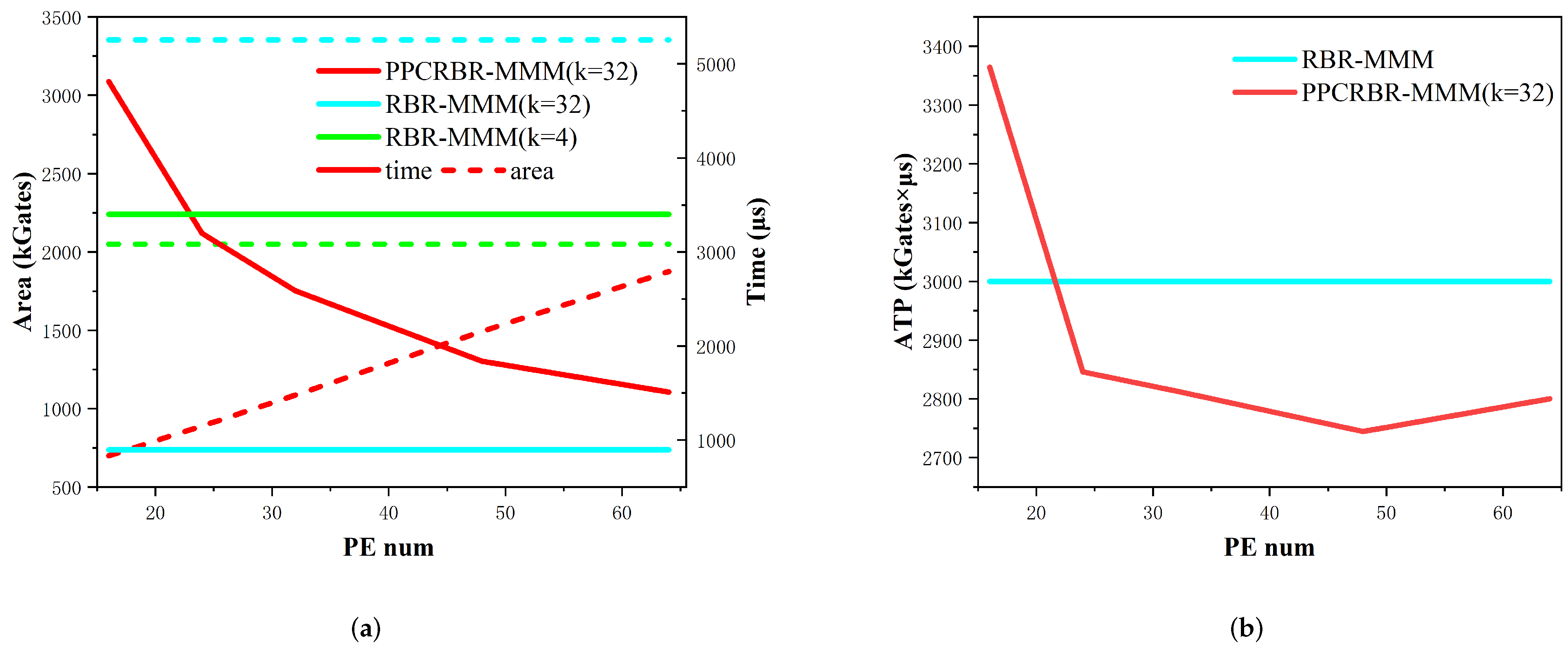
5. Experimental Results and Comparisons

5.1. Experiments of PPCRBR-MMM and RBR-MMM Algorithms

In order to better demonstrate the advantages of PPCRBR-MMM over the RBR-MMM algorithm, we use Verilog to implement the two algorithms and use the TSMC process library to synthesize to obtain area and delay information under different parameters. According to the analysis of critical path and area in the previous article, when the input bit width is high, the proportion of control logic in the total area due to pipelining will be reduced, which can better reflect the superiority of PPCRBR-MMM algorithm in ATP and customizability, at the same time, to make the comparison of experimental results general, we selected two designs with different parameters under the input of 1024 bits, 2048 bits, and 8192 bits for implementation. For better performance, we apply the parameter condition of k = 16 to the two algorithms with 1024 bits width and the parameter condition of k = 32 to the case of 2048 bits input. For the 8192 bits input, although a higher k value can bring higher performance and algorithm improvement, choosing a higher k will bring too high an area requirement, so we still choose the parameter condition of k = 32 . To reflect the advantages of customization, we analyzed the PPCRBR-MMM algorithm when the number of PEs under the input of 8192 bits is 16, 24, 32, 48, 64.

5.2. Results and Comparisons

Table 1 shows the area and time consuming comparison of RBR-MMM and PPCRBR-MMM under different input parameters. When the input is 1024 bits or 2048 bits, it can be seen that to obtain better performance, the RBR-MMM algorithm must have higher area consumption. And the pipeline algorithm can achieve better delay and area through lower pipeline stages, thereby increasing ATP by about 20%. When the input is 8192 bits, our algorithm still has a 10% advantage in ATP. Compared with the lower input bit width, the area consumption of the buffer for storing the intermediate results becomes larger, so the magnitude of improvement becomes smaller. The loss of this area can be reduced by the memory module external to the algorithm module, as mentioned above. Figure 6 exhibits the comparison of the area and time consumption of RBR-MMM and PPCRBR-MMM with different parameters under 8192 bits input. When the PE number is low, our algorithm will provide a lower area and higher latency. When the PE number becomes high, since the area of the PE is still the main part of the algorithm, the total area loss increases almost linearly. At the same time, because the critical path caused by high fan-out becomes longer, the frequency of the algorithm will decrease significantly when the number of PEs is large, so the delay cannot be reduced linearly. The final ATP results are shown in Figure 6b. When the PE number is increased to 48, the ATP improvement of the algorithm reaches the best.
Similarly, to further reflect the advantages of our algorithm on ATP, we compared the design under different parameters with some modules. The results are delivered in Table 2. Ref. [22] introduces the half-carry-save form to reduce the bit width of the operand in the CPA, thereby reducing the delay of the critical path. However, it still has the problem of a long carry chain compared with the redundant number system, so it cannot achieve a good performance in a lower area. Ref. [23] uses the full-carry-save method to parallelize the results of modular multiplication, but there are many splitting processes for the intermediate results, resulting in a less outstanding performance in multiple loops. Refs. [10,24] achieve a higher frequency by applying a customized CSA design, but their design require more cycles to complete more iterations, and finally cannot achieve higher performance and ATP value. Ref. [25] reorganizes the operands on the basis of [19] to achieve low memory bandwidth and high frequency while keeping the number of iterations unchanged, but its delay chain under high input bit width contains two-stage multiplication and addition modules, so the balance between frequency and total number of cycles cannot be achieved. Although [11] also uses the full-carry-save method, it uses CPA to complete the data conversion in the iterative process, thus reducing the overall running frequency. Ref. [5] uses the RNS-based modular multiplication system to achieve better frequency and ATP, but it avoids the pipeline design like [21]. In this paper, RBR is introduced to lessen the critical path in calculating units. While by modifying the algorithm, a full pipeline is achieved during iteration. Then we decompose the critical path of calculating q logic using the convenience of the pipeline, thus increasing the overall frequency. Finally, lower latency and better ATP results were achieved.

6. Conclusions

This paper presents a pipeline pre-calculated redundant binary representation Montgomery Modular Multiplication for a low ATP and customizable solution in big integer modular multiplication. The main purpose is to perform pipeline processing for the RBR-MMM algorithm and reduce the delay between different stages to 1 cycle by reconstructing the algorithm process. And with the advantage of streamlining, the critical path is decomposed, so as to effectively increase the operating frequency of the system. Both this algorithm’s correctness and advantage in ATP were provided by analysis between PPCRBR-MMM and RBR-MMM. Based on those algorithms, various hardware designs of different parameters, including input bit width, radix, and PE num, have been implemented to clarify our algorithm’s flexibility and superiority. The experimental data show that our PPCRBR-MMM algorithm has 10% to 20% improvement in ATP compared to RBR-MMM depending on the input bit width.

Author Contributions

Conceptualization, Z.Z. and P.Z.; methodology, Z.Z.; software, Z.Z.; validation, Z.Z.; formal analysis, Z.Z.; investigation, Z.Z.; resources, Z.Z.; data curation, Z.Z.; writing—original draft preparation, Z.Z.; writing—review and editing, Z.Z. and P.Z.; visualization, Z.Z.; supervision, Z.Z.; project administration, Z.Z. All authors have read and agreed to the published version of the manuscript.

Funding

This work is supported by the National Key R&D Program of China (2021YFB2206200).

Institutional Review Board Statement

Not applicable.

Informed Consent Statement

Not applicable.

Data Availability Statement

The data presented in this study are available on request from the corresponding author after publication. The data are not publicly available due to privacy or ethical restrictions.

Acknowledgments

Thanks to HJ-micro for providing high-performance server to support our research.

Conflicts of Interest

The authors declare no conflict of interest.

Abbreviations

The following abbreviations are used in this manuscript:
MMMMontgomery Modular Multiplication
RBRRedundant Binary Representation

References

  1. Montgomery, P.L. Modular multiplication without trial division. Math. Comput. 1985, 44, 519–521. [Google Scholar] [CrossRef]
  2. Ding, J.; Li, S. A low-latency and low-cost Montgomery modular multiplier based on NLP multiplication. IEEE Trans. Circuits Syst. II Express Briefs 2019, 67, 1319–1323. [Google Scholar] [CrossRef]
  3. Gu, Z.; Li, S. A division-free Toom–Cook multiplication-based Montgomery modular multiplication. IEEE Trans. Circuits Syst. II Express Briefs 2018, 66, 1401–1405. [Google Scholar] [CrossRef]
  4. Dai, W.; Chen, D.D.; Cheung, R.C.; Koc, C.K. Area-time efficient architecture of FFT-based montgomery multiplication. IEEE Trans. Comput. 2016, 66, 375–388. [Google Scholar] [CrossRef]
  5. Mo, Y.; Li, S. Design of an 8192-bit RNS montgomery multiplier. In Proceedings of the 2017 International Conference on Electron Devices and Solid-State Circuits (EDSSC), Hsinchu, Taiwan, 18–20 October 2017; pp. 1–2. [Google Scholar]
  6. Kolagatla, V.R.; Desalphine, V.; Selvakumar, D. Area-Time Scalable High Radix Montgomery Modular Multiplier for Large Modulus. In Proceedings of the 2021 25th International Symposium on VLSI Design and Test (VDAT), Surat, India, 16–18 September 2021; pp. 1–4. [Google Scholar] [CrossRef]
  7. Wang, S.H.; Lin, W.C.; Ye, J.H.; Shieh, M.D. Fast scalable radix-4 Montgomery modular multiplier. In Proceedings of the 2012 IEEE International Symposium on Circuits and Systems (ISCAS), Seoul, Korea, 20–23 May 2012; pp. 3049–3052. [Google Scholar] [CrossRef]
  8. Rentería-Mejía, C.P.; Trujillo-Olaya, V.; Velasco-Medina, J. 8912-bit Montgomery multipliers using radix-8 booth encoding and coded-digit. In Proceedings of the 2013 IEEE 4th Latin American Symposium on Circuits and Systems (LASCAS), Cusco, Peru, 27 February–1 March 2013; pp. 1–4. [Google Scholar] [CrossRef]
  9. Erdem, S.S.; Yanık, T.; Çelebi, A. A General Digit-Serial Architecture for Montgomery Modular Multiplication. IEEE Trans. Very Large Scale Integr. VLSI Syst. 2017, 25, 1658–1668. [Google Scholar] [CrossRef]
  10. Nti, R.B.; Ryoo, K. Area-efficient design of modular exponentiation using montgomery multiplier for RSA cryptosystem. In Advanced Multimedia and Ubiquitous Engineering; Springer: Berlin/Heidelberg, Germany, 2018; pp. 431–437. [Google Scholar]
  11. Kuang, S.R.; Wu, K.Y.; Lu, R.Y. Low-cost high-performance VLSI architecture for Montgomery modular multiplication. IEEE Trans. Very Large Scale Integr. VLSI Syst. 2015, 24, 434–443. [Google Scholar] [CrossRef]
  12. Sassaw, G.; Jiménez, C.J.; Valencia, M. High radix implementation of Montgomery multipliers with CSA. In Proceedings of the 2010 International Conference on Microelectronics, Cairo, Egypt, 19–22 December 2010; pp. 315–318. [Google Scholar] [CrossRef]
  13. Mahapatra, P.P.; Agrawal, S. RSA Cryptosystem with Modified Montgomery Modular Multiplier. In Proceedings of the 2017 IEEE International Conference on Computational Intelligence and Computing Research (ICCIC), Coimbatore, India, 14–16 December 2017; pp. 1–6. [Google Scholar] [CrossRef]
  14. Zode, P.P.; Deshmukh, R.B. Fast modular multiplication using parallel prefix adder. In Proceedings of the 2014 2nd International Conference on Emerging Technology Trends in Electronics, Communication and Networking, Surat, India, 26–27 December 2014; pp. 1–4. [Google Scholar]
  15. Sutter, G.D.; Deschamps, J.P.; Imaña, J.L. Modular multiplication and exponentiation architectures for fast RSA cryptosystem based on digit serial computation. IEEE Trans. Ind. Electron. 2010, 58, 3101–3109. [Google Scholar] [CrossRef]
  16. Fatemi, S.; Zare, M.; Khavari, A.F.; Maymandi-Nejad, M. Efficient implementation of digit-serial Montgomery modular multiplier architecture. IET Circuits Devices Syst. 2019, 13, 942–949. [Google Scholar] [CrossRef]
  17. Srinitha, S.; Niveda, S.; Rangeetha, S.; Kiruthika, V. A High Speed Montgomery Multiplier used in Security Applications. In Proceedings of the 2021 3rd International Conference on Signal Processing and Communication (ICPSC), Coimbatore, India, 13–14 May 2021; pp. 299–303. [Google Scholar] [CrossRef]
  18. Ibrahim, A.; Gebali, F.; Elsimary, H. New and improved word-based unified and scalable architecture for radix 2 Montgomery modular multiplication algorithm. In Proceedings of the 2013 IEEE Pacific Rim Conference on Communications, Computers and Signal Processing (PACRIM), Victoria, BC, Canada, 27–29 August 2013; pp. 153–158. [Google Scholar] [CrossRef]
  19. Shieh, M.D.; Lin, W.C. Word-Based Montgomery Modular Multiplication Algorithm for Low-Latency Scalable Architectures. IEEE Trans. Comput. 2010, 59, 1145–1151. [Google Scholar] [CrossRef]
  20. Tenca, A.; Koc, C. A scalable architecture for modular multiplication based on Montgomery’s algorithm. IEEE Trans. Comput. 2003, 52, 1215–1221. [Google Scholar] [CrossRef]
  21. Li, B.; Wang, J.; Ding, G.; Fu, H.; Lei, B.; Yang, H.; Bi, J.; Lei, S. A high-performance and low-cost montgomery modular multiplication based on redundant binary representation. IEEE Trans. Circuits Syst. II Express Briefs 2021, 68, 2660–2664. [Google Scholar] [CrossRef]
  22. Ding, Y.; Hu, J.; Wang, D.; Tan, H. A High-Performance RSA Coprocessor Based on Half-Carry-Save and Dual-Core MAC Architecture. Chin. J. Electron. 2018, 27, 70–75. [Google Scholar] [CrossRef]
  23. Miyamoto, A.; Homma, N.; Aoki, T.; Satoh, A. Systematic design of RSA processors based on high-radix Montgomery multipliers. IEEE Trans. Very Large Scale Integr. VLSI Syst. 2010, 19, 1136–1146. [Google Scholar] [CrossRef]
  24. Wu, T. Reducing memory requirements in CSA-based scalable Montgomery modular multipliers. In Proceedings of the 2014 12th IEEE International Conference on Solid-State and Integrated Circuit Technology (ICSICT), Guilin, China, 28–31 October 2014; pp. 1–3. [Google Scholar]
  25. Lin, W.C.; Ye, J.H.; Shieh, M.D. Scalable Montgomery Modular Multiplication Architecture with Low-Latency and Low-Memory Bandwidth Requirement. IEEE Trans. Comput. 2014, 63, 475–483. [Google Scholar] [CrossRef]
Figure 1. Computing quotient logic in RBR-MMM.
Electronics 11 03712 g001
Figure 2. Data dependence graph for Algorithm PPCRBR-MMM.
Electronics 11 03712 g002
Figure 3. Block diagram of PPCRBR-MMM.
Electronics 11 03712 g003
Figure 4. Schedule of typical PPCRBR-MMM.
Electronics 11 03712 g004
Figure 5. Brief schematic of PE unit in PPCRBR-MMM. (a) Computing temp result logic. (b) Computing MSB bits. (c) Computing output of PE.
Electronics 11 03712 g005
Figure 6. ATP result of PPCRBR-MMM for 8192 bits design. (a) Area and time cost for two algorithms. (b) ATP comparison of two algorithms with different PE num.
Electronics 11 03712 g006
Table 1. Comparison of RBR-MMM and PPCRBR-MMM.
AlgParamTechFreq
(MHz)
Area
(KGates)
CyclesTime
(ns)
ATP
1024-bit MMM
RBR-MMMk = 465 nm685121.825837745.92
90 nm435108.725859364.47
k = 1665 nm385304.46616650.53
PPCRBR-MMMp = 16
k = 16
65 nm617185.416426649.28
p = 24
k = 16
65 nm617222.411418541.09
90 nm392198.511429157.69
2048-bit MMM
RBR-MMMk = 465 nm654224.8514786176.69
k = 3265 nm302900.066218196.63
PPCRBR-MMMp = 16
k = 32
65 nm485506.3164338171.19
p = 24
k = 32
65 nm485707.1114235166.22
90 nm308631.1114370233.37
8192-bit MMM
RBR-MMMk = 465 nm603878.1205034002985.25
130 nm200945.52050102509691.38
k = 3265 nm2883353.92588963006.70
PPCRBR-MMMp = 16
k = 32
65 nm452699.2217848163367.41
p = 24
k = 32
65 nm446889.9142832032850.12
p = 32
k = 32
65 nm4461087.0115625932818.12
p = 48
k = 32
65 nm4281493.878818422751.53
130 nm142160878855548932.61
p = 64
k = 32
65 nm4251875.264415162841.92
Table 2. Comparison of different MMM implementation.
RefTechFreq (MHz)Area (KGates)CyclesTime (ns)ATP
1024-bit MMM
[22]90 nm36947.211533124147.45
[23]90 nm47211.42207468053.35
[10]90 nm88584.01026115997.36
[24]90 nm90997.059565563.54
[25]90 nm595103.014852496257.07
Ours90 nm392198.511429157.69
2048-bit MMM
[11]90 nm227336.0172476462569.06
Ours90 nm308631.1114370233.37
8192-bit MMM
[5]130 nm2631240.0211880569989.44
Ours130 nm142160878855548932.61
Publisher’s Note: MDPI stays neutral with regard to jurisdictional claims in published maps and institutional affiliations.

