Abstract
Virtual synchronous generators (VSGs) with inertia characteristics are generally adopted for the control of distributed generators (DGs) in order to mimic a synchronous generator. However, since the amount of virtual inertia in VSG control is usually constant and given by trial and error, the real power and frequency oscillations of a battery energy storage system (BESS) occurring under load variation result in the degradation of the control performance of the DG. Thus, in this study, a novel virtual inertia estimation methodology is proposed to estimate suitable values of virtual inertia for VSGs and to suppress the real power output and frequency oscillations of the DG under load variation. In addition, to improve the function of the proposed virtual inertia estimator and the transient responses of the real power output and frequency of the DG, an online-trained Petri probabilistic wavelet fuzzy neural network (PPWFNN) controller is proposed to replace the proportional integral (PI) controller. The network structure and the online learning algorithm using backpropagation (BP) of the proposed PPWFNN are represented in detail. Finally, on the basis of the experimental results, it can be concluded that superior performance in terms of real power output and frequency response under load variation can be achieved by using the proposed virtual inertia estimator and the intelligent PPWFNN controller.
1. Introduction
In recent years, the percentage of distributed generators (DGs) based on renewable energy sources has been significantly increasing [1,2] due to the increased awareness of environmental pollution. However, a serious issue arises with respect to the stability of the power system. In general, conventional synchronous generators (SGs) are adopted to stabilize the frequency of the power grid [3,4]. By means of absorbing or delivering the kinetic energy stored in the rotor of SG, the frequency response of the power grid can be smoothed owing to the inertial response [3,4]. Moreover, a large amount of kinetic energy can also be delivered to the utility grid in cases of a sudden disturbance or fault [5,6]. However, since inverter-based DGs lack inertia and are without grid-forming capability, the stability of the power grid is threatened [7,8]. Thus, in order to overcome the drawbacks of inverter-based DGs, various algorithms for virtual synchronous generators (VSGs) have recently been proposed [9,10]. The main principle of the VSG’s control is the adoption of the well-known swing equation for SG based on droop control [11,12]. Hence, the VSG control imitates the basic characteristics of the SG, including the inertia and the droop mechanism, so that rotating inertia can be emulated in inverter-based DGs. The VSG possesses the ability to provide grid support and to improve the stability of frequency and power flow. Furthermore, the VSG control can also perform in an islanded operation mode, naturally guaranteeing load sharing [13], which is similar to traditional SGs [7,8]. Hence, there have been many studies focusing on VSG control, as reviewed in [14,15]. In [13], a new algorithm based on a finite-control-set model-predictive-control scheme and a corrective VSG control was proposed to suppress the distorted current waveform. In addition, an improved synchronization stability method that adopts the frequency difference between the power grid and VSG for reactive power control was researched in [14]. A fuzzy-secondary-controller-based VSG for grid-connected inverters of DGs was proposed in [15] to regulate the voltage and frequency of microgrid systems.
The frequency and power output oscillations under sudden disturbances, which are inherent characteristics of real SGs as well as VSGs, can be introduced by the swing equation [16,17]. In general, since conventional SGs possess considerable overload capability, this is not a serious issue for SGs. However, the inverter-based DGs adopt VSG control without overload capability in order to ride though large fluctuations [16]. Deterioration, as well as serious frequency and power flow oscillations, will result in damage to the equipment during sudden disturbances. Although the oscillations during disturbances can be mitigated by adjusting the parameters of the swing equation, such as the damping factor and the virtual inertia, the low moment of the inertia results in a deterioration in frequency stability and can cause large frequency oscillations during disturbances [15]. Moreover, since the swing equation of the VSG control is nonlinear and it is difficult to obtain the proper parameters, the parameters of the swing equation are generally constants and are given by trial and error [18]. In other words, the characeristics of the VSG can be changed by means of adjusting the damping factor and the virtual inertia of the swing equation [17].
In the past decade, in many studies, wavelet fuzzy neural networks (WFNNs) have been proposed to solve the system identification, signal processing, time-series prediction, regression and control issues [19,20]. Since WFNNs integrate a fuzzy neural network (FNN) with wavelet transform theory, they possess the ability of FNN to deal with complex nonlinear systems and parallel computation, and the capabilities of wavelet transform theory for quick convergence, fault tolerance, high accuracy and approximation [21,22]. In [22], a robust WFNN identifier was investigated to improve the function of the micro permanent magnet synchronous motor drive. In [23], a self-learning WFNN controller was adopted to regulate the dc-link voltage of the induction generator system for wind power applications. Moreover, the probabilistic neural network (PNN) was first proposed as a data classifier by Specht in 1990 [24,25]. The main principle of the PNN is the adoption of a Bayes classification rule along with probability density function estimation as a pattern layer for each training sample [26,27]. The PNN possesses classification capability and is good at processing high-dimensional data [28]. Furthermore, the PNN has been widely adopted in the area of nonlinear mapping, pattern recognition, approximation and fault diagnosis [27,29]. In addition, Petri net (PN) is a powerful mathematical and graphical tool for solving deadlocks in flexible manufacturing systems and discrete event systems owing to the ability to cope with conflicts and concurrences [30,31]. Thus, in accordance with the above merits of WFNN, PNN and PN, a new online-trained Petri probabilistic wavelet fuzzy neural network (PPWFNN) controller is proposed for the first time in this study.
To suppress the real power output and frequency oscillations of a battery energy storage system (BESS) using VSG control under load variation, a novel virtual inertia estimator is proposed for the first time to estimate suitable values of virtual inertia for the VSG control, and verified in islanded operation. Moreover, to improve the performance of the proposed virtual inertia estimator and the transient responses of the real power output and frequency of the BESS, an online-trained PPWFNN controller using real power error as input is proposed to take the place of the proportional integral (PI) controller. The operating principles of the proposed virtual inertia estimator for VSG control are introduced in Section 2. The network structure and online learning based on the backpropagation (BP) algorithm of the proposed PPWFNN controller are described in Section 3. Moreover, the feasibility and effectiveness of the proposed virtual inertia estimator and PPWFNN controller for the BESS using VSG under various load variation conditions are manifested in Section 4. Finally, some conclusions are expressed in Section 5.
The novelty and major contributions of this study can be described as follows:
- The successful development of a virtual inertia estimator for VSG control.
- The successful development of the proposed online-trained PPWFNN controller.
- The successful implementation of a BESS using the proposed virtual inertia estimator and PPWFNN controller for the inertia estimator of the VSG control under load variation.
2. Operating Theory of Proposed Virtual Inertia Estimator for VSG Control
In this study, a BESS operated in islanded mode is investigated by using the proposed virtual inertia estimator and PPWFNN intelligent controller. A block diagram of the BESS is represented in Figure 1. The BESS is equipped with a varying load, regarded as sudden disturbances, in order to certify the performance of the proposed algorithms. The detailed operating theories of the BESS using the proposed virtual inertia estimation methodology are described in the following.
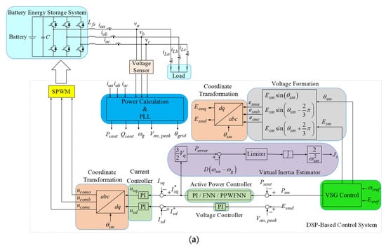
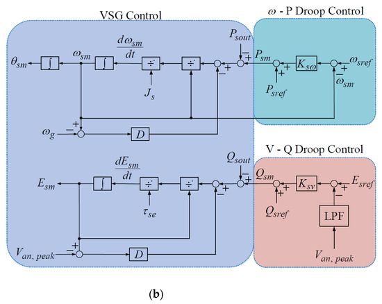
Figure 1.
Block diagram of BESS. (a) Control block of BESS using proposed virtual inertia estimator and PPWFNN intelligent controller; (b) control block of VSG based on droop control.
2.1. Control Algorithm of VSG
The control block of the BESS using the proposed virtual inertia estimator and PPWFNN intelligent controller is shown in Figure 1a. The BESS is performed in islanded mode and VSG control is adopted to imitate the basic characteristics of the SG, including the inertia and the droop mechanism, so that the rotating inertia can be emulated in the BESS. The control block of the VSG based on droop control is provided in Figure 1b. In general, VSG control adopts the well-known swing equations of the SG based on angular frequency–real power and voltage–reactive power droop control. In this study, the designed characteristics of and droop control are illustrated in Figure 2a,b, and given as follows [15,16]:
where is the virtual shaft real power of the VSG; is the set value of real power; is the droop coefficient; is the reference angular frequency; is the virtual rotor angular frequency of the VSG; is the virtual shaft reactive power of the VSG; is the set value of reactive power; is the droop coefficient; is the reference voltage; is the voltage output of the VSG. Moreover, the swing equation for the VSG control shown in Figure 1b is described as [15,16]:
where is the actual real power output; is the virtual inertia; is the virtual damping factor; is the output angular frequency. According to Equation (3), if the virtual damping factor and the virtual inertia are set to zero, the swing Equation (3) is equal to the droop control shown in Equation (1). In other words, the droop control is the special case of the VSG control and without the inertial characteristic [6,16]. Furthermore, Equation (3) can be rewritten as follows, and is shown in Figure 1b:
where is the virtual rotor angle. In addition, a similar control concept can be applied to the droop control as follows [9]:
where is the actual reactive power output; is a time constant; is the amplitude of virtual internal electromotive force of the VSG. Equation (5) can be rewritten as follows, and is also shown inFigure 1b:
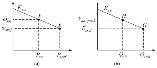
Figure 2.
Droop control. (a) droop; (b) droop.
The virtual rotor angle and the amplitude of virtual internal electromotive force of the VSG are sent to the voltage formation shown in Figure 1a to obtain the three-phase induced electromotive force . Furthermore, the dq-axis induced electromotive forces and are obtained using coordinate transformation.
2.2. Proposed Virtual Inertia Estimator for VSG
In Figure 1a, the three-phase output voltages and output currents of the BESS are detected and sent to the power calculation and phase-lock-loop (PLL) unit to compute the actual real power output , the reactive power output , the output angular frequency , and the voltage output . Then, the tracking error between the virtual shaft real power and the actual real power output is sent to the real power controller, namely the traditional PI or FNN or the proposed PPWFNN intelligent controller, to obtain the q-axis current command . In this study, the main principle of the proposed virtual inertia estimation methodology is obtained and derived as follows, according to Equation (3):
Hence, the product of the value 3/2, the q-axis current command and the q-axis voltage obtained by the three-phase output voltages with the coordinate transformation is equal to the real power error [1,2]. Since the real power error is also equivalent to the value , the estimated virtual inertia in Equation (7) can be rewritten based on the real power error as follows:
Therefore, by means of the q-axis current command regulated by the PI or FNN or the proposed PPWFNN controller, the suitable virtual inertia of the VSG control can be estimated to suppress the real power output and frequency oscillations of the BESS using VSG control under the load variation according to Equation (8). Moreover, the d-axis induced electromotive force is compared to the voltage output and regulated by the PI controller to obtain the d-axis current command . The dq-axis current commands and are compared to the dq-axis current and obtained by the output currents of the BESS with the coordinate transformation. Finally, the control signals for the sinusoidal pulse width modulation (SPWM) switching signals are obtained by means of coordinate transformation.
3. Online-Trained PPWFNN Controller
To increase the performance of the proposed virtual inertia estimator, an online-trained PPWFNN controller is proposed to take the place of the PI controller to regulate the q-axis current command of the BESS using VSG control under load variation. The proposed PPWFNN controller is made up of an input layer, a membership layer, a Petri layer, a probabilistic layer, a wavelet layer, a rule layer, and an output layer. The network structure of the proposed PPWFNN is provided in Figure 3. The network structure, online learning algorithm and convergence analysis of the proposed PPWFNN controller are introduced in detail in the following.
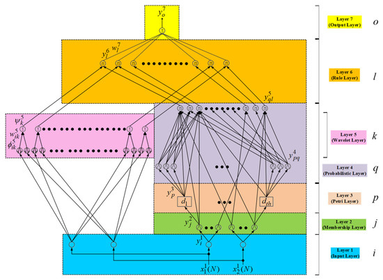
Figure 3.
Network structure of proposed PPWFNN controller.
3.1. Network Structure
Layer 1 (Input Layer): The input and output of the node are depicted as follows:
where N expresses the Nth iteration; ; . The input variables of the proposed PPWFNN controller are the tracking error between the virtual shaft real power and the actual real power output , namely , and its derivative for the proposed virtual inertia estimator of the BESS using VSG control under load variation.
Layer 2 (Membership Layer): To implement the membership function, the Gaussian function is adopted in each node to carry out the fuzzification operation. For the jth node,
where and are the standard deviation and the mean of the Gaussian function, respectively, in the jth term input linguistic variable to the node of membership layer.
Layer 3 (Petri Layer): The main purpose of the Petri layer is to take advantage of the competition law to choose the proper fired nodes [2] for the generation of tokens. When the tokens are generated in input position, the transitions are in enable state. Thereupon, the transition is unfired or fired in accordance with Equations (13) and (14).
where is the transition; and are positive constants and are set as 1.3 and 0.06; is the dynamic threshold value and is modulated by the function as follows [2,23]:
When the transition is fired, the token is moved from its input position to the output position. Moreover, when the transition is unfired, the token remains in the input position. Consequently, the output and input of the Petri layer can be described as follows:
Layer 4 (Probabilistic Layer): A general Gaussian function is used for the receptive field function, expressed as:
where and represent the normal deviation and the mean, respectively; is the output of this layer.
Layer 5 (Wavelet Layer): The wavelet function is carried out and introduced as follows:
where is ith in the kth term wavelet output to the node of wavelet sum layer; is the wavelet weight of the units in the wavelet function layer; is the kth term wavelet function output to the node of the wavelet layer.
Layer 6 (Rule Layer): The signal propagation of the rule layer performs the operation, which multiplies the input signals and the outputs the resulting product. The relationship of the input and output of the rule layer is expressed in the following:
where , and are the jth, pth and kth inputs to the node of the ruler layer; is the output of the probabilistic layer.
Layer 7 (Output Layer): The operation, which calculates the overall outputs as the summation of all input signals, is implemented, and can be depicted as follows:
where is the connective weight between the rule layer and the output layer; is the output of the proposed PPWFNN controller, which is equal to the q-axis current command shown in Figure 1a for the regulation of the real power output and the virtual inertia estimator of the BESS.
3.2. Online Learning
In this study, by means of the supervised gradient descent method, the proposed PPWFNN controller possesses online learning capability. The online-trained PPWFNN controller derives an error function with regard to the variables of the network by using the chain rule algorithm. The error function is depicted as:
The process of the learning algorithm of the proposed PPWFNN controller is expressed in detail as follows:
Output Layer: The propagated error term can be depicted as:
Through the chain rule, the connected weight can be updated and computed as follows:
where is the learning rate. Then, the connected weight is updated as:
Rule Layer: In the rule layer, the error terms to be propagated are introduced as:
Wavelet Layer: Two error terms of the wavelet layer to be propagated are computed as follows:
The updates of the connected weight are calculated using the chain rule:
where is learning rate. Hence, the connective weight can be updated in accordance with the following equation:
Membership Layer: The error term to be propagated and computed is given as:
Moreover, the updated amounts of the standard deviation and the mean of the membership function, respectively, are obtained according to the chain rule as follows:
where and are the learning rates of the mean and standard deviation, respectively. Then, the updated standard deviation and mean of the membership function are obtained as follows:
Owing to uncertainties such as external disturbance and parameter variation in the dynamic of the BESS, the correct computation of the Jacobian of the BESS, , cannot be achieved. Consequently, to solve this issue and to increase the online learning rate of the network parameter, the delta adaptation law is used in the following [1,2].
The main objective of the proposed PPWFNN controller is to online train the parameters shown in Equations (31), (36), (40) and (41) for the q-axis current command of the BESS to achieve the minimum real power error and obtain the optimum virtual inertia of the VSG control under load variation. Hence, a suitable virtual inertia of the VSG control can be obtained to suppress the real power output and frequency oscillations of DG under load variation.
3.3. Convergence Analysis
In this study, to effectively train the proposed PPWFNN intelligent controller, the varied learning rates [32,33] are derived. The objective of the convergence analysis is to derive the specific learning rate coefficient for the network parameter that guarantees the convergence of the q-axis current command of the BESS using VSG control by the analysis of the discrete-type Lyapunov function.
Regarding the error function in Equation (28) as a discrete-type Lyapunov function, the variation of the Lyapunov function is depicted as:
Subsequently, the linearized model [33] of the error equation is expressed, via Equations (30), (35), (38) and (39), by
where , , and depict the change of connective weights in the output layer and wavelet layer, and the change in the mean and the standard deviation of the Gaussian function in the membership layer, respectively. If the learning rate parameters of the proposed PPWFNN are designed as:
where is a positive constant, Equation (44) can be redescribed as:
In accordance with Equations (28) and (49), the convergence of the proposed PPWFNN control can be guaranteed. Thereupon, the intelligent control of the q-axis current of the BESS using VSG for real power control will gradually converge to the real power command.
4. Experimental Results
To verify the effectiveness of the proposed virtual inertia estimator and the online-trained PPWFNN controller for the suitable virtual inertia of the VSG control under load variation, a BESS using VSG control was designed and implemented using the digital signal processor (DSP) control platform. The designed BESS using VSG control was operated in islanding mode. Moreover, the block diagram and photo of the BESS are presented in Figure 4a,b, respectively. In Figure 4a, the three-phase output voltages and output currents of the BESS are detected and sent to the peripheral circuit for the control algorithms, including the power calculation, PLL, VSG, the proposed virtual inertia estimator, and the PPWFNN controller. The control algorithms of the BESS are implemented by the DSP TMS320F28335 with a sampling time of 1 ms. A switching frequency of 16 kHz was adopted in the control platform. In addition, the droop coefficients and were set to be 500 W/(rad/s) and 20 Var/V, respectively. The virtual damping factor was set to be 0.01. The parameters of the PI controller for the q-axis current command were obtained by trial and error to achieve superior control performance. The resulting parameters were .
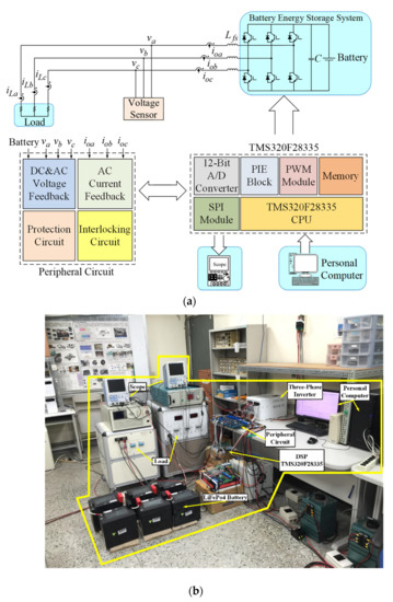
Figure 4.
BESS using VSG control. (a) Block diagram of DSP-based BESS; (b) photo of experimental setup.
Owing to the unsuitable virtual inertia of the VSG control, the real power output and frequency oscillations of the BESS occurring under load variation resulted in deterioration of the control performance of the BESS. Consequently, to prove the effectiveness of the BESS using the proposed virtual inertia estimator and PPWFNN controller, two test cases were designed for the experiment, as follows: (1) Case 1: BESS using VSG control with different values of moment of virtual inertia under load variation; and (2) Case 2: BESS using the proposed virtual inertia estimator under load variation. Moreover, in order to compare the control performance of the proposed PPWFNN controller, the experimental results obtained using PI and FNN controllers for the control of the q-axis current command with the proposed virtual inertia estimator in case 2 are demonstrated in this study.
In case 1, the characteristics and performance of the BESS using VSG control with different values of moment of virtual inertia under load variation were demonstrated. In this scenario, different values of virtual inertia of = 0 , 0.002713 , 0.00407 and 0.0407 were adopted. The load was changed from 1 kW to 2 kW at 0.5 s. The experimental results of the BESS using VSG control with = 0 are illustrated in Figure 5a–c. The responses of the real power output and the reactive power output of the BESS are shown in Figure 5a. The responses of the line-to-line voltage and the output current of the BESS are shown in Figure 5b. The response of the virtual rotor frequency of VSG control is provided in Figure 5c. According to the experimental results, shown in Figure 5a–c, since the virtual inertia = 0 was adopted in the VSG control of the BESS, the characteristics of the BESS using VSG control were similar to the BESS using droop control under load variation [6]. Hence, the real power output , output current , and virtual rotor frequency respond rapidly. Moreover, the experimental results of the BESS using VSG control with = 0.002713 are provided in Figure 6a–c. The responses of the real power output and the reactive power output of the BESS are shown in Figure 6a. The responses of the line-to-line voltage and the output current of the BESS are shown in Figure 6b. The responses of the virtual rotor frequency of the VSG control and the virtual inertia are provided in Figure 6c. From the experimental results as shown in Figure 6, although a virtual inertia of = 0.002713 was adopted in the VSG control, the oscillation phenomena of the real power output , output current , and virtual rotor frequency seriously deteriorate the control performance of the BESS under load variation owing to the low moment of virtual inertia [15]. Furthermore, the experimental results of the BESS using VSG control with = 0.00407 and = 0.0407 are represented in Figure 7 and Figure 8, respectively. In accordance with the experimental results shown in Figure 7 and Figure 8, the larger the moment of virtual inertia , the more sluggish the response of the oscillations of real power output , output current , and virtual rotor frequency . Therefore, from the experimental results shown in Figure 5, Figure 6, Figure 7 and Figure 8, when the amount of virtual inertia in the VSG is unsuitable, oscillations in the real power output and frequency of the BESS will occur under load variation.
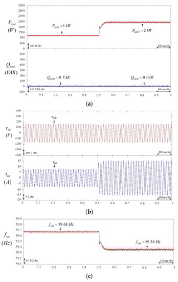
Figure 5.
BESS using VSG control with constant virtual inertia = 0 . (a) Responses of real power output and reactive power output of BESS; (b) responses of line-to-line voltage and output current of BESS; (c) response of virtual rotor frequency of VSG control.
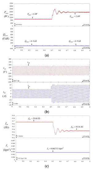
Figure 6.
BESS using VSG control with constant virtual inertia = 0.002713 . (a) Responses of real power output and reactive power output of BESS. (b) Responses of line-to-line voltage and output current of BESS. (c) Responses of virtual rotor frequency of VSG control and virtual inertia .
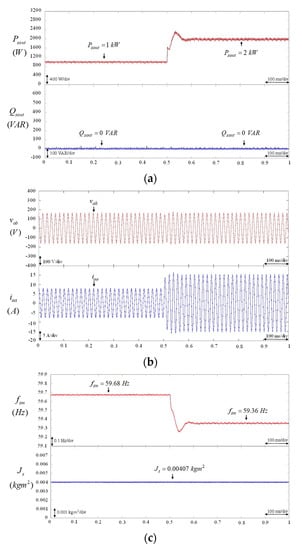
Figure 7.
BESS using VSG control with constant virtual inertia = 0.00407 . (a) Responses of real power output and reactive power output of BESS; (b) Responses of line-to-line voltage and output current of BESS; (c) Responses of virtual rotor frequency of VSG control and virtual inertia .
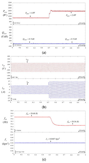
Figure 8.
BESS using VSG control with constant virtual inertia = 0.0407 . (a) Responses of real power output and reactive power output of BESS; (b) Responses of line-to-line voltage and output current of BESS; (c) Responses of virtual rotor frequency of VSG control and virtual inertia .
To overcome the above drawback and to suppress the real power output and frequency oscillations of the BESS using VSG control under load variation, the experimental results of the BESS using the proposed virtual inertia estimator with the PI, FNN, and the proposed PPWFNN controllers, respectively, for the control of the q-axis current command were tested in case 2. In this case, the load was changed from 0.25 kW to 2 kW and then changed to 1 kW. First, the experimental results of the PI-controlled BESS using the proposed virtual inertia estimator are provided in Figure 9. The responses of the real power output and the reactive power output of the BESS are shown in Figure 9a. The responses of the line-to-line voltage and the output current of the BESS are presented in Figure 9b. The responses of the virtual rotor frequency of the VSG control and the estimated virtual inertia are provided in Figure 9c. From the experimental results, when the load changes at 1.5 s and 3.5 s, the proposed virtual inertia estimator can effectively estimate the virtual inertia , as shown in Figure 9c. Although the oscillation phenomena of the real power output , output current , and virtual rotor frequency of the BESS using VSG control can be reduced, as shown in Figure 9a–c, the deteriorated transient responses of the power output and frequency are still obvious at 1.5 s and 3.5 s owing to the poor robustness of the control property of the PI controller. Then, the experimental results of the FNN-controlled BESS using the proposed virtual inertia estimator are provided in Figure 10. The responses of the real power output and the reactive power output of the BESS are illustrated in Figure 10a. The responses of the line-to-line voltage and the output current of the BESS are presented in Figure 10b. The responses of the virtual rotor frequency of VSG control and the estimated virtual inertia are shown in Figure 10c. According to the experimental results of the FNN-controlled BESS, the proposed virtual inertia estimator can effectively estimate the suitable virtual inertia , as shown in Figure 10c under load variation. Moreover, as a result of estimating a suitable value of virtual inertia , the transient responses of the real power output , the output current , and the frequency of the BESS using VSG control can be improved at 1.5 s and 3.5 s, as shown in Figure 10b,c. In addition, the experimental results of the proposed PPWFNN-controlled BESS using the proposed virtual inertia estimator are given in Figure 11. The responses of the real power output and the reactive power output of the BESS are presented in Figure 11a. The responses of the line-to-line voltage and the output current of the BESS are provided in Figure 11b. The responses of the virtual rotor frequency of VSG control and the estimated virtual inertia are shown in Figure 11c. Since the proposed PPWFNN controller incorporates the merits of WFNN, PNN and PN, compared to the experimental results using PI- and FNN-controlled BESSs, the proposed PPWFNN-controlled BESS with the virtual inertia estimator can provide more effective estimation of the virtual inertia under load variation. Furthermore, the oscillation phenomena of the real power output , output current , and virtual rotor frequency of the proposed PPWFNN-controlled BESS using VSG control were much reduced at 1.5 s and 3.5 s, as shown in Figure 11a–c. In addition, the maximum real power and frequency error of PI-, FNN-, and the proposed PPWFNN-controlled BESSs using the proposed virtual inertia estimator under different load variation conditions are provided in Table 1. According to the experimental results and Table 1, the transient responses of the power output and the virtual rotor frequency of the proposed PPWFNN-controlled BESS are superior to the PI- and FNN-controlled BESSs owing to the powerful control ability of the proposed PPWFNN controller. Therefore, the feasibility and the effectiveness of the proposed virtual inertia estimator with the PPWFNN controller for VSG control are confirmed.
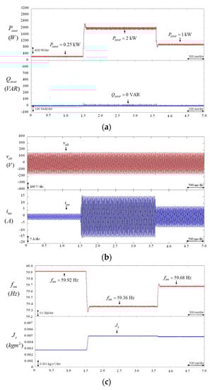
Figure 9.
PI-controlled BESS using proposed virtual inertia estimator. (a) Responses of real power output and reactive power output of BESS; (b) Responses of line-to-line voltage and output current of BESS; (c) Responses of virtual rotor frequency of VSG control and estimated virtual inertia .
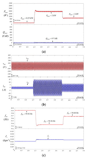
Figure 10.
FNN-controlled BESS using proposed virtual inertia estimator. (a) Responses of real power output and reactive power output of BESS; (b) responses of line-to-line voltage and output current of BESS; (c) responses of virtual rotor frequency of VSG control and estimated virtual inertia .
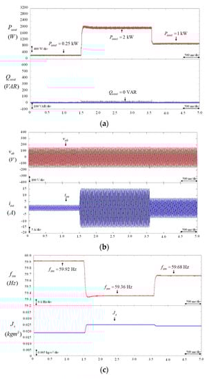
Figure 11.
PPWFNN-controlled BESS using proposed virtual inertia estimator. (a) Responses of real power output and reactive power output of BESS; (b) responses of line-to-line voltage and output current of BESS; (c) responses of virtual rotor frequency of VSG control and estimated virtual inertia .

Table 1.
Maximum real power error and frequency error of PI-, FNN- and proposed PPWFNN-controlled BESSs using proposed virtual inertia estimator under load variation.
In this study, the compute or training time of the “C” program in the TMS320F28335 32-bit floating-point DSP with 150 MHz can be obtained by the clock tool of Texas Instruments (TI) Code Composer Studio (CCS) v6 program editing interface. The total operation cycles and total execution time of the PI-, FNN- and the proposed PPWFNN-controlled BESSs are compared in Table 2. The total operation cycles and total execution time for the proposed PPWFNN are 8700 cycles and 58 us, respectively. In consequence, the total execution time of BESS using the proposed PPWFNN controller is still less than 1 ms, which is the sampling interval of the control loop.
Table 2.
Compute time of PI-, FNN- and proposed PPWFNN-controlled BESSs.
5. Conclusions
Since the amount of virtual inertia of the VSG control is usually constant and given by trial and error, the real power output and frequency oscillations of BESS using VSG control usually occur under abrupt disturbances owing to unsuitable virtual inertia. In this study, to overcome this problem, a virtual inertia estimation methodology was successfully developed and implemented to estimate a suitable virtual inertia for VSG control and to suppress the real power output and frequency oscillations of the BESS under load variation. Moreover, in order to improve the performance of the proposed virtual inertia estimator and the transient response of the real power output and frequency of the BESS, an online-trained PPWFNN controller was proposed to replace the conventional PI controller for the regulation of the q-axis current command . Furthermore, the feasibility and the effectiveness of the BESS using the proposed virtual inertia estimator and PPWFNN controller were verified by experimental results. According to the experimental results, the proposed PPWFNN-controlled BESS with the virtual inertia estimator was able to effectively estimate suitable virtual inertia under various load variation conditions. Thus, the transient responses of the power output and frequency of the proposed PPWFNN-controlled BESS were better than the PI- and FNN-controlled BESSs owing to the powerful control capability of the proposed PPWFNN.
The major contributions of this study are: (i) the successful development of a virtual inertia estimator for VSG control; (ii) the successful development of the proposed online-trained PPWFNN controller; (iii) the successful implementation of a BESS using the proposed virtual inertia estimator and PPWFNN controller for the inertia estimator of the VSG control under load variation.
Author Contributions
Conceptualization, K.-H.T. and F.-J.L.; methodology, K.-H.T. and F.-J.L.; software, T.-Y.T.; validation, T.-Y.T., M.-Y.L. and Y.-D.L.; formal analysis, M.-Y.L.; investigation, K.-H.T. and F.-J.L.; resources, T.-Y.T. and M.-Y.L.; data curation, Y.-D.L.; writing—original draft preparation, K.-H.T. and F.-J.L.; writing—review and editing, K.-H.T. and F.-J.L. All authors have read and agreed to the published version of the manuscript.
Funding
This work was supported in part by the Ministry of Science and Technology of Taiwan, R.O.C., under grant MOST 110-3116-F-008-001 and in part by the Institute of Nuclear Energy Research, R.O.C., under grant 110A010.
Conflicts of Interest
The authors declare no conflict of interest.
References
- Tan, K.H.; Lin, F.J.; Shih, C.M.; Kuo, C.N. Intelligent control of microgrid with virtual inertia using recurrent probabilistic wavelet Fuzzy neural network. IEEE Trans. Power Electron. 2020, 35, 7451–7464. [Google Scholar] [CrossRef]
- Tan, K.H.; Tseng, T.Y. Seamless switching and grid reconnection of microgrid using petri recurrent wavelet fuzzy neural network. IEEE Trans. Power Electron. 2021, 36, 11847–11861. [Google Scholar] [CrossRef]
- Saadatmand, S.; Shamsi, P.; Ferdowsi, M. Power and frequency regulation of synchronverters using a model free neural network-based predictive controller. IEEE Trans. Ind. Electron. 2021, 68, 3662–3671. [Google Scholar] [CrossRef]
- Fang, J.; Tang, Y.; Li, H.; Li, X. A battery/ultracapacitor hybrid energy storage system for implementing the power management of virtual synchronous generators. IEEE Trans. Power Electron. 2018, 33, 2820–2824. [Google Scholar] [CrossRef]
- Alipoor, J.; Miura, Y.; Ise, T. Power system stabilization using virtual synchronous generator with alternating moment of inertia. IEEE J. Emerg. Sel. Top. Power Electron. 2015, 3, 451–458. [Google Scholar] [CrossRef]
- Liu, J.; Miura, Y.; Ise, T. Comparison of dynamic characteristics between virtual synchronous generator and droop control in inverter-based distributed generators. IEEE Trans. Power Electron. 2016, 31, 3600–3611. [Google Scholar] [CrossRef]
- Wu, H.; Ruan, X.; Yang, D.; Chen, X.; Zhao, W.; Lv, Z.; Zhong, Q.C. Small-signal modeling and parameters design for virtual synchronous generators. IEEE Trans. Ind. Electron. 2016, 63, 4292–4303. [Google Scholar] [CrossRef]
- Xu, Q.; Dragicevic, T.; Xie, L.; Blaabjerg, F. Artificial intelligence-based control design for reliable virtual synchronous generators. IEEE Trans. Power Electron. 2021, 36, 9453–9464. [Google Scholar] [CrossRef]
- Pan, D.; Wang, X.; Liu, F.; Shi, R. Transient stability of voltage-source converters with grid-forming control: A design-oriented study. IEEE J. Emerg. Sel. Top. Power Electron. 2020, 8, 1019–1033. [Google Scholar] [CrossRef]
- Wang, W.; Jiang, L.; Cao, Y.; Li, Y. A parameter alternating VSG controller of VSC-MTDC systems for low frequency oscillation damping. IEEE Trans. Power Syst. 2020, 35, 4609–4620. [Google Scholar] [CrossRef]
- Xiong, X.; Wu, C.; Hu, B.; Pan, D.; Blaabjerg, F. Transient damping method for improving the synchronization stability of virtual synchronous generators. IEEE Trans. Power Electron. 2021, 36, 7820–7831. [Google Scholar] [CrossRef]
- Zhong, Q.C.; Weiss, G. Synchronverters: Inverters that mimic synchronous generators. IEEE Trans. Ind. Electron. 2011, 58, 1259–1267. [Google Scholar] [CrossRef]
- Jongudomkarn, J.; Liu, J.; Yanagisawa, Y.; Bevrani, H.; Ise, T. Model predictive control for indirect boost matrix converter based on virtual synchronous generator. IEEE Access 2020, 8, 60364–60381. [Google Scholar] [CrossRef]
- Xiong, X.; Wu, C.; Blaabjerg, F. An improved synchronization stability method of virtual synchronous generators based on frequency feedforward on reactive power control loop. IEEE Trans. Power Electron. 2021, 36, 9136–9148. [Google Scholar] [CrossRef]
- Andalib-Bin-Karim, C.; Liang, X.; Zhang, H. Fuzzy-secondary-controller-based virtual synchronous generator control scheme for interfacing inverters of renewable distributed generation in microgrids. IEEE Trans. Ind. Appl. 2018, 54, 31047–31061. [Google Scholar] [CrossRef]
- Liu, J.; Miura, Y.; Bevrani, H.; Ise, T. Enhanced virtual synchronous generator control for parallel inverters in microgrids. IEEE Trans. Smart Grid 2017, 8, 2268–2277. [Google Scholar] [CrossRef]
- Wang, F.; Zhang, L.; Feng, X.; Guo, H. An adaptive control strategy for virtual synchronous generator. IEEE Trans. Ind. Appl. 2018, 54, 124–5133. [Google Scholar] [CrossRef]
- Shintai, T.; Miura, Y.; Ise, T. Oscillation damping of a distributed generator using a virtual synchronous generator. IEEE Trans. Power Deliv. 2014, 29, 668–676. [Google Scholar] [CrossRef]
- Abiyev, R.H.; Kaynak, O. Fuzzy wavelet neural networks for identification and control of dynamic plants—a novel structure and a comparative study. IEEE Trans. Ind. Electron. 2008, 55, 3133–3140. [Google Scholar] [CrossRef]
- Yilmaz, S.; Oysal, Y. Fuzzy wavelet neural network models for prediction and identification of dynamical systems. IEEE Trans. Neural Netw. 2010, 21, 1599–1609. [Google Scholar] [CrossRef]
- Huang, W.; Oh, S.K.; Pedrycz, W. Fuzzy wavelet polynomial neural networks: Analysis and design. IEEE Trans. Fuzzy Syst. 2017, 25, 1329–1341. [Google Scholar] [CrossRef]
- El-Sousy, F.F.M.; Amin, M.M.; Mohammed, O.A. Robust optimal control of high-speed permanent-magnet synchronous motor drives via self-constructing fuzzy wavelet neural network. IEEE Trans. Ind. Appl. 2021, 57, 999–1013. [Google Scholar] [CrossRef]
- Tan, K.H. Squirrel-cage induction generator system using wavelet petri fuzzy neural network control for wind power applications. IEEE Trans. Power Electron. 2016, 31, 5242–5254. [Google Scholar] [CrossRef]
- Specht, D.F. Probabilistic neural network. Neural Netw. 1990, 3, 109–118. [Google Scholar] [CrossRef]
- Rutkowski, L. Adaptive probabilistic neural networks for pattern classification in time-varying environment. IEEE Trans. Neural Netw. 2004, 15, 11–827. [Google Scholar] [CrossRef] [Green Version]
- Kusy, M.; Zajdel, R. Application of reinforcement learning algorithms for the adaptive computation of the smoothing parameter for probabilistic neural network. IEEE Trans. Neural Netw. Learn. Syst. 2015, 26, 2163–2175. [Google Scholar] [CrossRef]
- Tripathy, M.; Maheshwari, R.P.; Verma, H.K. Power transformer differential protection based on optimal probabilistic neural network. IEEE Trans. Power. Deliv. 2010, 25, 102–112. [Google Scholar] [CrossRef]
- Li, Y.; Guo, S.; Zhu, L.; Mukai, T.; Gan, Z. Enhanced probabilistic inference algorithm using probabilistic neural networks for learning control. IEEE Access 2019, 7, 184457–184467. [Google Scholar] [CrossRef]
- Beritelli, F.; Capizzi, G.; Sciuto, G.L.; Napoli, C.; Scaglione, F. Rainfall estimation based on the intensity of the received signal in a LTE/4G mobile terminal by using a probabilistic neural network. IEEE Access 2018, 6, 30865–30873. [Google Scholar] [CrossRef]
- Wang, P.; Ma, L.; Goverde, R.M.P.; Wang, Q. Rescheduling trains using petri nets and heuristic search. IEEE Trans. Intell. Transp. Syst. 2016, 17, 726–735. [Google Scholar] [CrossRef]
- Siljak, H.; Psara, K.; Philippou, A. Distributed antenna selection for massive MIMO using reversing petri nets. IEEE Wirel. Commun. Lett. 2019, 8, 1427–1430. [Google Scholar] [CrossRef]
- Yoo, S.J.; Choi, Y.H.; Park, J.B. Generalized predictive control based on self-recurrent wavelet neural network for stable path tracking of mobile robots: Adaptive learning rates approach. IEEE Trans. Circuits Syst. I-Regul. Pap. 2006, 53, 1381–1395. [Google Scholar]
- Wai, R.J.; Li, C.M. Design of dynamic petri recurrent fuzzy neural network and its application to path-tracking control of nonholonomic mobile robot. IEEE Trans. Ind. Electron. 2009, 56, 2667–2683. [Google Scholar]
Publisher’s Note: MDPI stays neutral with regard to jurisdictional claims in published maps and institutional affiliations. |
© 2021 by the authors. Licensee MDPI, Basel, Switzerland. This article is an open access article distributed under the terms and conditions of the Creative Commons Attribution (CC BY) license (https://creativecommons.org/licenses/by/4.0/).