
Proposal for a Localization System for an IoT Ecosystem


Abstract
:1. Introduction
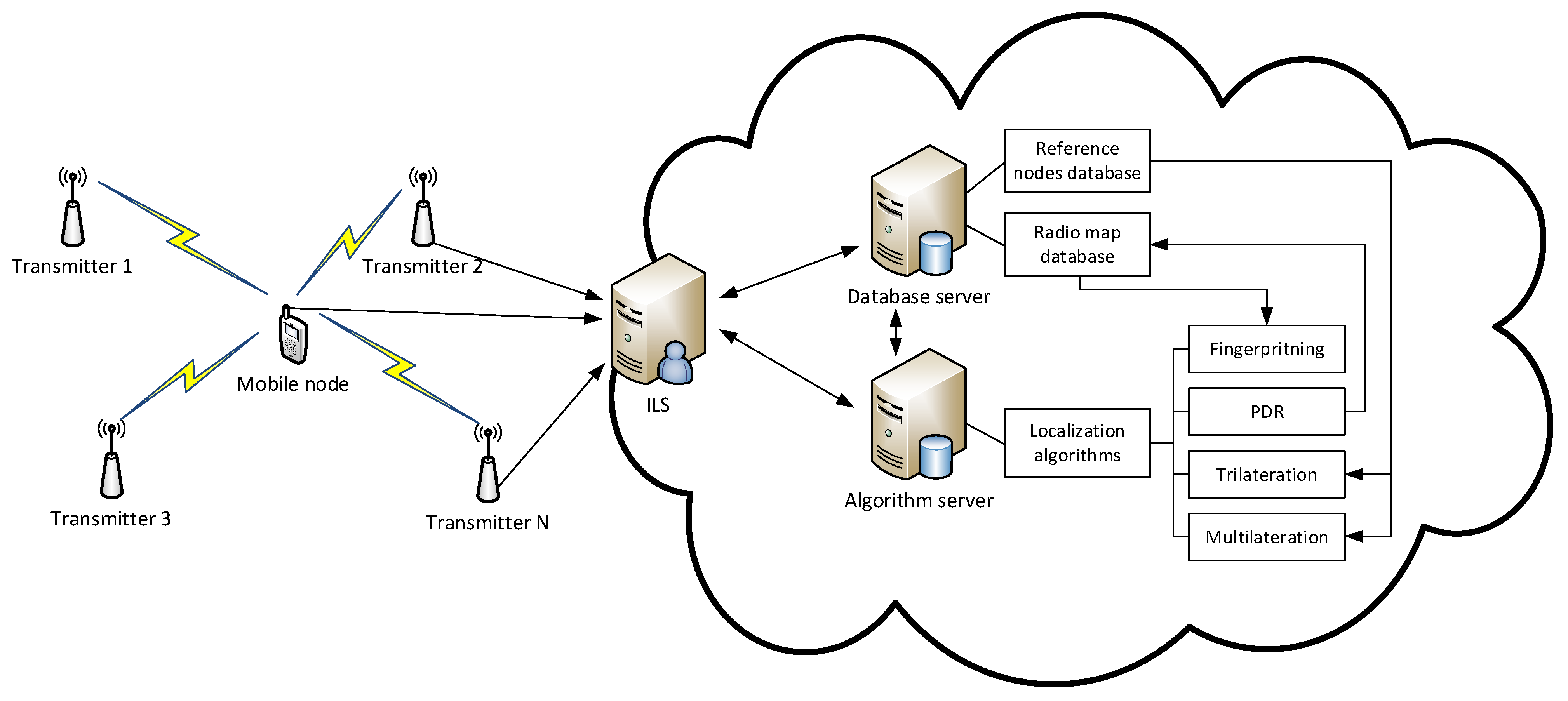
- Proposal of an integrated localization system that is capable of handling positioning requests from IoT nodes in both indoor and outdoor environments.
- Proposal of a system that supports a multi-RAT approach and automatically selects the most suitable positioning module for the given IoT device based on parameters of localization data that are delivered to the positioning system.
2. Related Work
2.1. IoT Localization Systems
2.2. Implemented Algorithms
2.2.1. Distance-Based—Lateration Algorithms
2.2.2. Distance-Free—Fingerprinting Algorithms
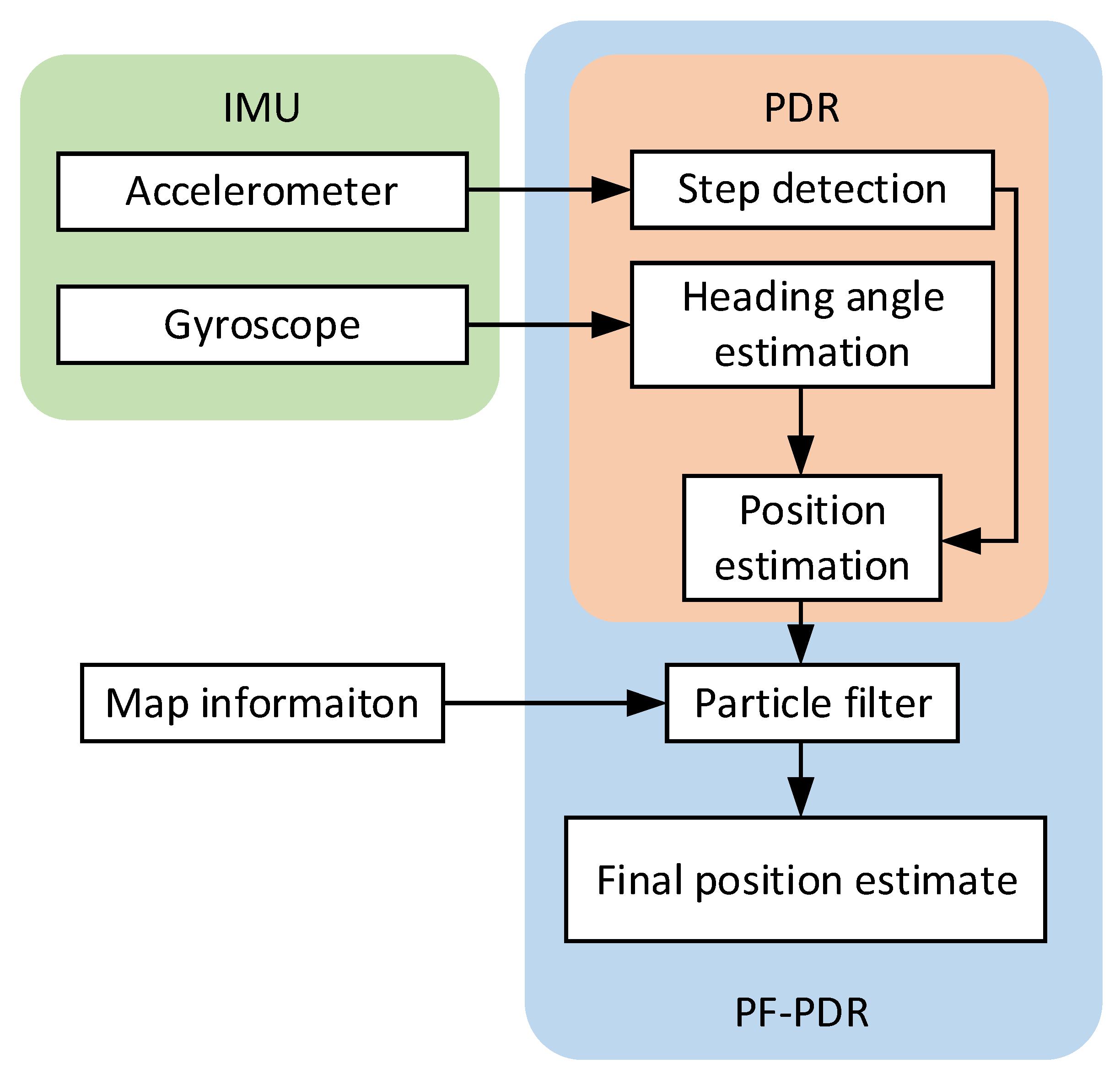
2.2.3. Inertial Positioning—Dead Reckoning Algorithms
3. Proposal of Integrated Localization System
| Algorithm 1 Integrated decision algorithm |
| INPUT: data received by the IoT server, radio map and reference nodes database |
| OUTPUT: position estimate |
| 1: begin |
| 2: extract data form IoT server for localization |
| 3: if data from both IMU and wireless technology were received then |
| 4: run PF-PDR algorithm to estimate position of mobile node |
| 5: run map fusion algorithm to update radio map database |
| 6: else if data only from wireless technology are received then |
| 7: if data from UWB is received then |
| 8: use lateration algorithm to estimate position |
| 9: else |
| 10: load data from radio map database |
| 11: compare data about transmitters from IoT server and radio map |
| 12: if transmitters are in radio map database then |
| 13: check radio map density and parameters |
| 14: select suitable algorithm and |
| 15: estimate position using fingerprinting algorithm |
| 16: end if |
| 17: load data from reference nodes database |
| 18: compare transmitters from IoT server and reference nodes database |
| 19: if overlap of transmitters > 3 then |
| 20: find number of transmitters with RSS above RSS_threshold |
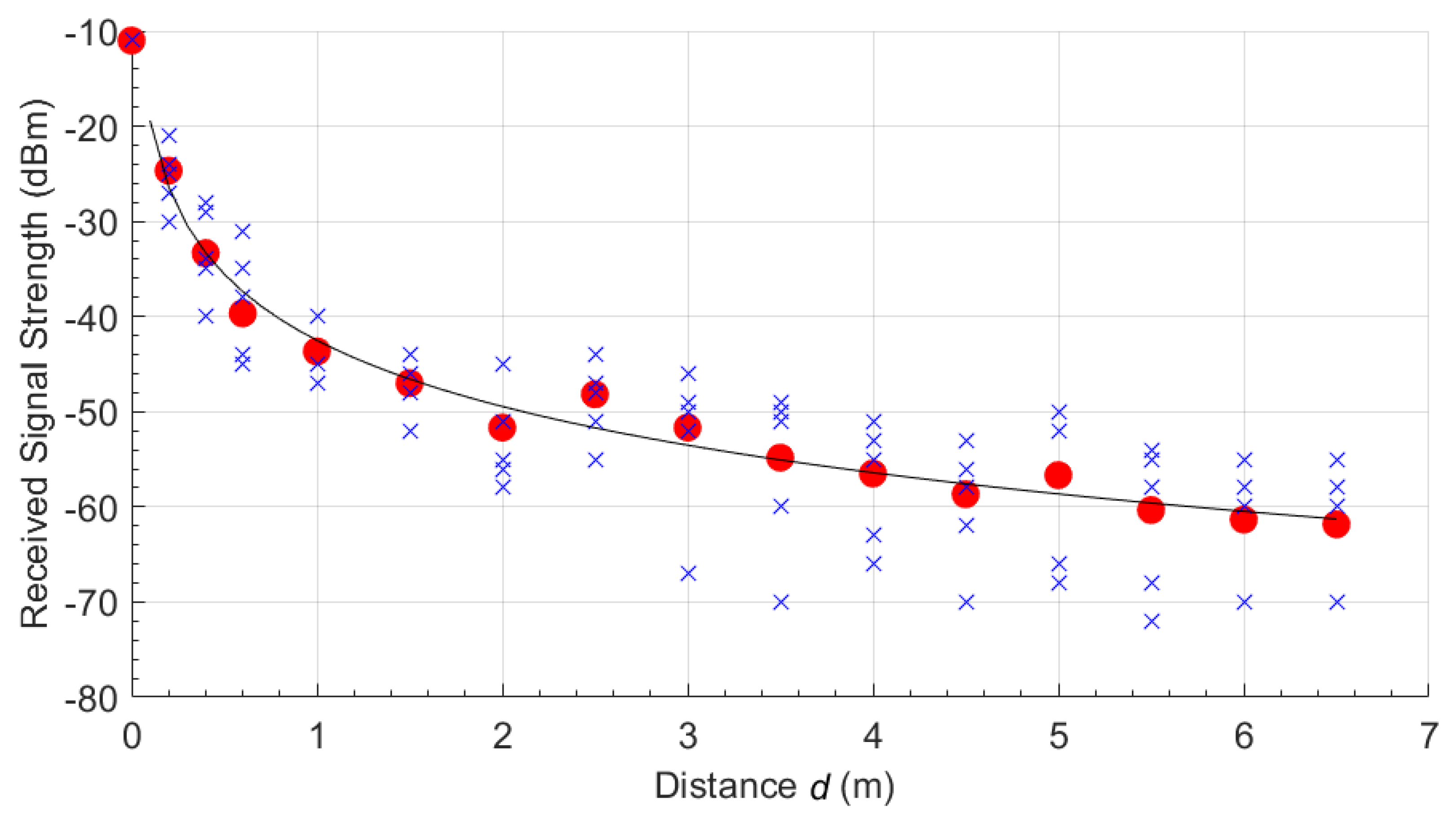
| 21: use propagation model for given technology to estimate distance |
| 22: if number of transmitters above RSS threshold is > 3 then |
| 23: use multilateration algorithm to estimate position |
| 24: else |
| 25: use trilateration algorithm to estimate position |
| 26: end if |
| 27: end if |
| 28: end if |
| 29: end if |
| 30: end |
4. Experimental Setup and Achieved Results
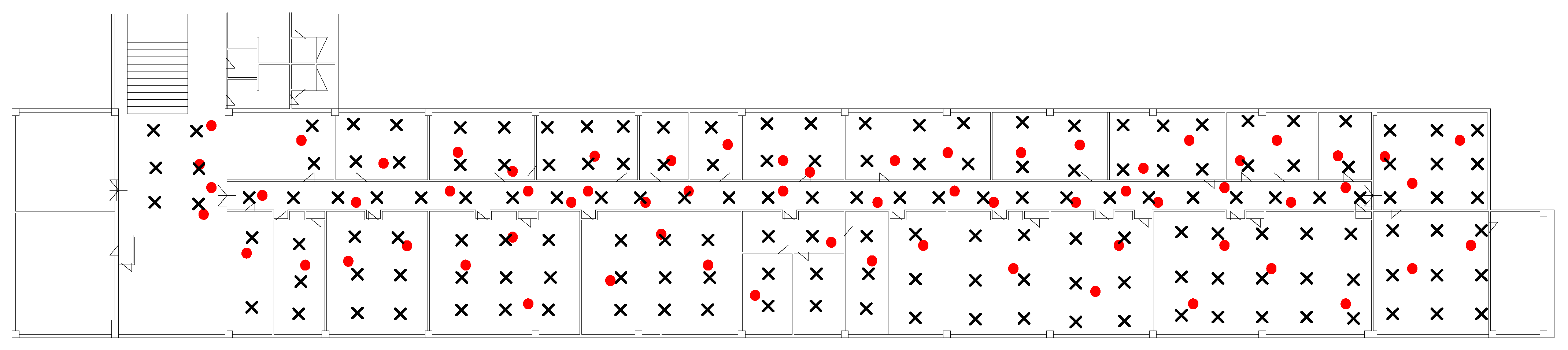
4.1. Experimental Setup
4.2. Achieved Results
5. Conclusions
Author Contributions
Funding
Data Availability Statement
Conflicts of Interest
References
- Lom, M.; Pribyl, O.; Svitek, M. Industry 4.0 as a Part of Smart Cities. In Proceedings of the 2016 Smart Cities Symposium Prague (SCSP), Prague, Czech Republic, 26–27 May 2016; pp. 1–6. [Google Scholar]
- Mikusova, M.; Wachnicka, J.; Zukowska, J. Research on the Use of Mobile Devices and Headphones on Pedestrian Crossings—Pilot Case Study from Slovakia. Safety 2021, 7, 17. [Google Scholar] [CrossRef]
- Saeed, I.A.; Selamat, A.; Rohani, M.F.; Krejcar, O.; Chaudhry, J.A. A Systematic State-of-the-Art Analysis of Multi-Agent Intrusion Detection. IEEE Access 2020, 8, 180184–180209. [Google Scholar] [CrossRef]
- Bonafini, F.; Fernandes Carvalho, D.; Depari, A.; Ferrari, P.; Flammini, A.; Pasetti, M.; Rinaldi, S.; Sisinni, E. Evaluating Indoor and Outdoor Localization Services for LoRaWAN in Smart City Applications. In Proceedings of the 2019 II Workshop on Metrology for Industry 4.0 and IoT (MetroInd4.0 IoT), Naples, Italy, 4–6 June 2019; pp. 300–305. [Google Scholar]
- Papan, J.; Segec, P.; Yeremenko, O.; Bridova, I.; Hodon, M. A New Bit Repair Fast Reroute Mechanism for Smart Sensors IoT Network Infrastructure. Sensors 2020, 20, 5230. [Google Scholar] [CrossRef] [PubMed]
- Diggelen, F.V. SYSTEM DESIGN & TEST-GNSS Accuracy-Lies, Damn Lies, and Statistics-This Update to a Seminal Article First Published Here in 1998 Explains How Statistical Methods Can Create Many Different. GPS World 2007, 18, 26–33. [Google Scholar]
- Jabborov, F.; Cho, J. Image-Based Camera Localization Algorithm for Smartphone Cameras Based on Reference Objects. Wirel. Pers. Commun. 2020, 114, 2511–2527. [Google Scholar] [CrossRef]
- Montoliu, R.; Torres-Sospedra, J.; Belmonte, O. Magnetic Field Based Indoor Positioning Using the Bag of Words Paradigm. In Proceedings of the 2016 International Conference on Indoor Positioning and Indoor Navigation (IPIN), Alcala de Henares, Spain, 4–7 October 2016; pp. 1–7. [Google Scholar]
- Niu, C.; Chang, H. Research on Indoor Positioning on Inertial Navigation. In Proceedings of the 2019 IEEE 2nd International Conference on Computer and Communication Engineering Technology (CCET), Beijing, China, 16–18 August 2019; pp. 55–58. [Google Scholar]
- Xiao, J.; Zhou, Z.; Yi, Y.; Ni, L.M. A Survey on Wireless Indoor Localization from the Device Perspective. ACM Comput. Surv. 2016, 49, 1–31. [Google Scholar] [CrossRef]
- Liu, H.; Darabi, H.; Banerjee, P.; Liu, J. Survey of Wireless Indoor Positioning Techniques and Systems. IEEE Trans. Syst. Man Cybern. Part C (Appl. Rev.) 2007, 37, 1067–1080. [Google Scholar] [CrossRef]
- Garcia, M.; Martinez, C.; Tomas, J.; Lloret, J. Wireless Sensors Self-Location in an Indoor WLAN Environment. In Proceedings of the 2007 International Conference on Sensor Technologies and Applications (SENSORCOMM 2007), Valencia, Spain, 14–20 October 2007; pp. 146–151. [Google Scholar]
- Liu, F.; Liu, J.; Yin, Y.; Wang, W.; Hu, D.; Chen, P.; Niu, Q. Survey on WiFi-Based Indoor Positioning Techniques. IET Commun. 2020, 14, 1372–1383. [Google Scholar] [CrossRef]
- Çiftler, B.S.; Kadri, A.; Güvenc, İ. IoT Localization for Bistatic Passive UHF RFID Systems With 3-D Radiation Pattern. IEEE Internet Things J. 2017, 4, 905–916. [Google Scholar] [CrossRef]
- Ye, Q.; Bie, H.; Li, K.C.; Gong, X.F.L.; He, X.; Fang, G. EdgeLoc: A Robust and Real-Time Localization System Towards Heterogeneous IoT Devices. IEEE Internet Things J. 2021. [Google Scholar] [CrossRef]
- Kwasme, H.; Ekin, S. RSSI-Based Localization Using LoRaWAN Technology. IEEE Access 2019, 7, 99856–99866. [Google Scholar] [CrossRef]
- Hu, K.; Chen, Y.; He, S.; Shi, Z.; Chen, J.; Tao, Z. ILoc: A Low-Cost Low-Power Outdoor Localization System for Internet of Things. In Proceedings of the 2019 IEEE Global Communications Conference (GLOBECOM), Waikoloa, HI, USA, 9–13 December 2019; pp. 1–6. [Google Scholar]
- Mikhaylov, K.; Stusek, M.; Masek, P.; Petrov, V.; Petajajarvi, J.; Andreev, S.; Pokorny, J.; Hosek, J.; Pouttu, A.; Koucheryavy, Y. Multi-RAT LPWAN in Smart Cities: Trial of LoRaWAN and NB-IoT Integration. In Proceedings of the 2018 IEEE International Conference on Communications (ICC), Kansas City, MO, USA, 20–24 May 2018; pp. 1–6. [Google Scholar]
- Mikhaylov, K.; Lema, M.A.; Andreev, S.; Gupta, R.; Galinina, O.; Destino, G.; Mahmoodi, T.; Dohler, M.; Koucheryavy, Y.; Valkama, M. Multi-Radio Perspectives for Massive MTC Localization: Energy Consumption and Utility. In Proceedings of the 2019 11th International Congress on Ultra Modern Telecommunications and Control Systems and Workshops (ICUMT), Dublin, Ireland, 28–30 October 2019; pp. 1–6. [Google Scholar]
- Aernouts, M.; Lemic, F.; Moons, B.; Famaey, J.; Hoebeke, J.; Weyn, M.; Berkvens, R. A Multimodal Localization Framework Design for IoT Applications. Sensors 2020, 20, 4622. [Google Scholar] [CrossRef] [PubMed]
- Rodas, J.; Barral, V.; Escudero, C.J. Architecture for Multi-Technology Real-Time Location Systems. Sensors 2013, 13, 2220–2253. [Google Scholar] [CrossRef] [PubMed] [Green Version]
- Garcia, M.; Tomás, J.; Boronat, F.; Lloret, J. The Development of Two Systems for Indoor Wireless Sensors Self-Location. Ad Hoc Sens. Wirel. Netw. 2009, 8, 235–258. [Google Scholar]
- Brida, P.; Machaj, J.; Benikovsky, J. A Modular Localization System as a Positioning Service for Road Transport. Sensors 2014, 14, 20274–20296. [Google Scholar] [CrossRef] [PubMed] [Green Version]
- Koppanyi, Z.; Toth, C.K. Indoor Ultra-Wide Band Network Adjustment Using Maximum Likelihood Estimation. ISPRS Ann. Photogramm. Remote Sens. Spat. Inf. Sci. 2014, II–1, 31–35. [Google Scholar] [CrossRef] [Green Version]
- Jimenez, A.R.; Seco, F.; Prieto, C.; Guevara, J. A Comparison of Pedestrian Dead-Reckoning Algorithms Using a Low-Cost MEMS IMU. In Proceedings of the 2009 IEEE International Symposium on Intelligent Signal Processing, Budapest, Hungary, 26–28 August 2009; pp. 37–42. [Google Scholar]
- Racko, J.; Brida, P.; Perttula, A.; Parviainen, J.; Collin, J. Pedestrian Dead Reckoning with Particle Filter for Handheld Smartphone. In Proceedings of the 2016 International Conference on Indoor Positioning and Indoor Navigation (IPIN), Alcala de Henares, Spain, 4–7 October 2016; pp. 1–7. [Google Scholar]
- Brida, P.; Machaj, J.; Racko, J.; Krejcar, O. Algorithm for Dynamic Fingerprinting Radio Map Creation Using IMU Measurements. Sensors 2021, 21, 2283. [Google Scholar] [CrossRef] [PubMed]
- Khedr, M.E.; El-Sheimy, N. SBAUPT: Azimuth SBUPT for Frequent Full Attitude Correction of Smartphone-Based PDR. IEEE Sens. J. 2020. [Google Scholar] [CrossRef]
- Kang, W.; Nam, S.; Han, Y.; Lee, S. Improved Heading Estimation for Smartphone-Based Indoor Positioning Systems. In Proceedings of the 2012 IEEE 23rd International Symposium on Personal, Indoor and Mobile Radio Communications-(PIMRC), Sydney, Australia, 9–12 September 2012; pp. 2449–2453. [Google Scholar]
- Kemppi, P.; Rautiainen, T.; Ranki, V.; Belloni, F.; Pajunen, J. Hybrid Positioning System Combining Angle-Based Localization, Pedestrian Dead Reckoning and Map Filtering. In Proceedings of the 2010 International Conference on Indoor Positioning and Indoor Navigation, Zurich, Switzerland, 15–17 September 2010; pp. 1–7. [Google Scholar]
- Hol, J.D.; Schon, T.B.; Gustafsson, F. On Resampling Algorithms for Particle Filters. In Proceedings of the 2006 IEEE Nonlinear Statistical Signal Processing Workshop, Cambridge, UK, 13–15 September 2006; pp. 79–82. [Google Scholar]
- Machaj, J.; Brida, P.; Piché, R. Rank Based Fingerprinting Algorithm for Indoor Positioning. In Proceedings of the 2011 International Conference on Indoor Positioning and Indoor Navigation, Guimaraes, Portugal, 21–23 September 2011; pp. 1–6. [Google Scholar]

| System | Wireless Technologies | Localization Algorithms | Mean Localization Error | Note |
|---|---|---|---|---|
| Garcia et al. [22] | Wi-Fi | Triangulation, fingerprinting | 0.9 m |
|
| Hu et al. [16] | LoRaWAN | Lateration | 11.2–17.9 m |
|
| Mikhaylov et al. [18] | LoRaWAN NB-IoT | Lateration | 150 m |
|
| Brida et al. [23] | GPS GSM Wi-Fi | Fingerprinting | 2.8 m indoors, 23 m outdoors |
|
| Bonafini et al. [4] | GPS UWB LoRaWAN | Lateration | 0.09–0.38 m |
|
| Aernouts et al. [20] | Sigfox LoRaWAN DASH7 GPS | Lateration, fingerprinting | 2.5 m (Dash7) 75 m (LoRa) 700 m (Sigfox) |
|
| Rodas et al. [21] | UWB ZigBee | Fingerprinting | ≈1 m |
|
| Proposed system | GSM Wi-Fi UWB ZigBee LoRaWAN | Fingerprinting, lateration | 0.6 m (UWB) up to 110 m (LoRa) |
|
| Technology | Environment | n | |
|---|---|---|---|
| Zigbee | Indoor | −42.5 | 2.309 |
| Outdoor | −47.5 | 1.99 | |
| LoRaWAN | Outdoor | −17 | 3.6 |
| Technology | Algorithm | Environment | Localization Error (m) | |||
|---|---|---|---|---|---|---|
| Mean | Median | std | 95% | |||
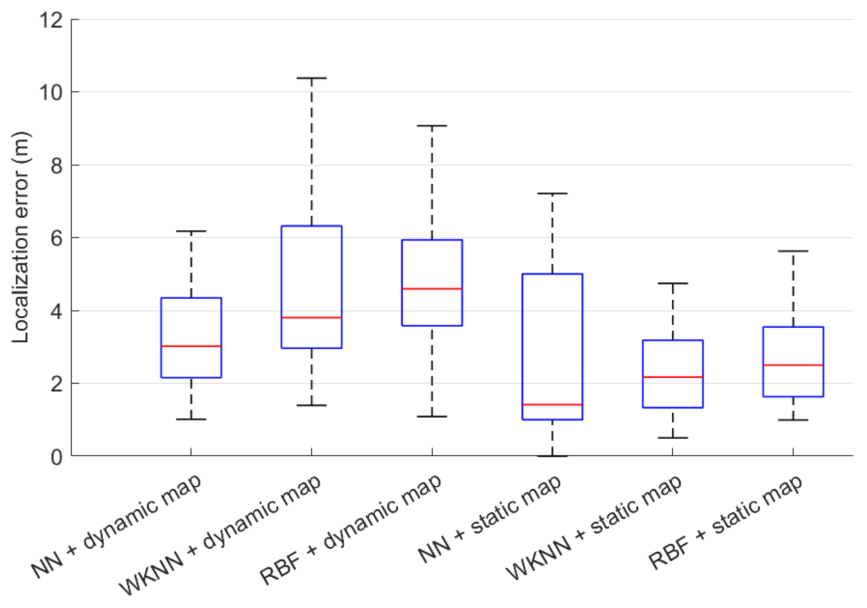
| Wi-Fi | NN dynamic | Indoors | 3.49 | 3.02 | 1.97 | 7.86 |
| WKNN dynamic | Indoors | 4.51 | 3.80 | 2.18 | 8.44 | |
| RBF dynamic | Indoors | 4.84 | 4.59 | 2.17 | 8.89 | |
| NN static | Indoors | 3.49 | 1.41 | 2.41 | 6.61 | |
| WKNN static | Indoors | 2.69 | 2.17 | 1.19 | 4.62 | |
| RBF static | Indoors | 2.98 | 2.49 | 1.66 | 6.55 | |
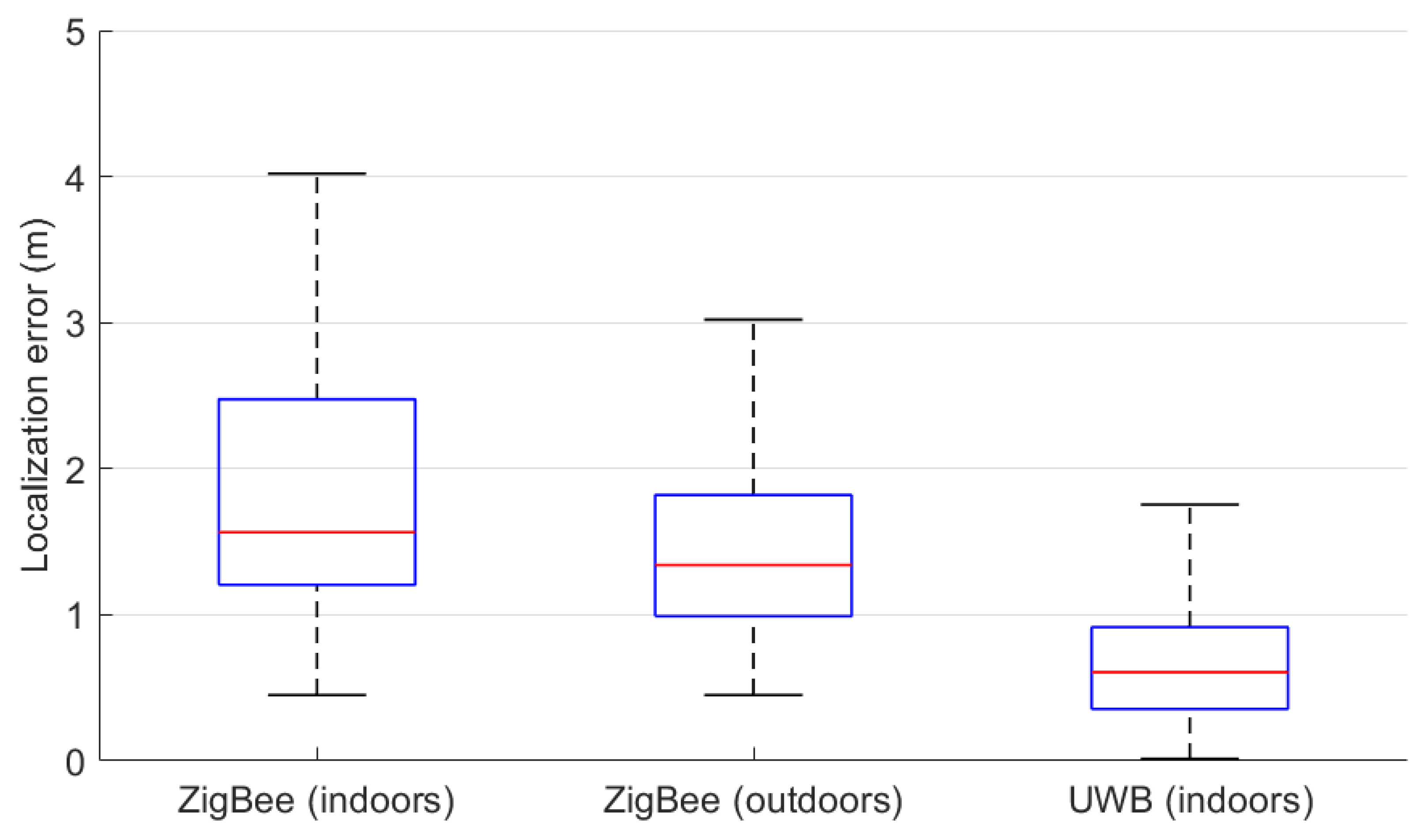
| ZigBee | Trilateration | Indoors | 1.96 | 1.57 | 1.20 | 4.47 |
| Trilateration | Outdoors | 1.61 | 1.34 | 0.98 | 3.87 | |
| UWB | Trilateration | Indoors | 0.68 | 0.61 | 0.43 | 1.51 |
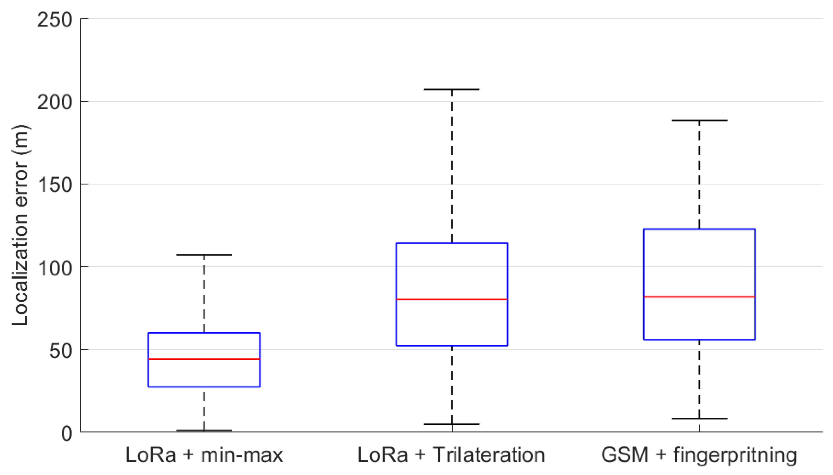
| LoRa | Min-max | Outdoors | 44.95 | 44.27 | 21.58 | 80.50 |
| Trilateration | Outdoors | 109.44 | 80.21 | 130.44 | 288.11 | |
| GSM | KNN | Outdoors | 94.44 | 81.88 | 51.09 | 181.31 |
Publisher’s Note: MDPI stays neutral with regard to jurisdictional claims in published maps and institutional affiliations. |
© 2021 by the authors. Licensee MDPI, Basel, Switzerland. This article is an open access article distributed under the terms and conditions of the Creative Commons Attribution (CC BY) license (https://creativecommons.org/licenses/by/4.0/).
Share and Cite
Machaj, J.; Brida, P.; Matuska, S. Proposal for a Localization System for an IoT Ecosystem. Electronics 2021, 10, 3016. https://doi.org/10.3390/electronics10233016
Machaj J, Brida P, Matuska S. Proposal for a Localization System for an IoT Ecosystem. Electronics. 2021; 10(23):3016. https://doi.org/10.3390/electronics10233016
Chicago/Turabian StyleMachaj, Juraj, Peter Brida, and Slavomir Matuska. 2021. "Proposal for a Localization System for an IoT Ecosystem" Electronics 10, no. 23: 3016. https://doi.org/10.3390/electronics10233016
APA StyleMachaj, J., Brida, P., & Matuska, S. (2021). Proposal for a Localization System for an IoT Ecosystem. Electronics, 10(23), 3016. https://doi.org/10.3390/electronics10233016