
A Bra Monitoring System Using a Miniaturized Wearable Ultra-Wideband MIMO Antenna for Breast Cancer Imaging

 , ,
, ,  ,
,  , , ,
, , ,  and
and 
Abstract
:1. Introduction
2. Design of the MIMO UWB Antenna
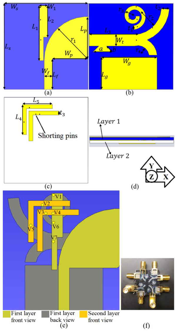
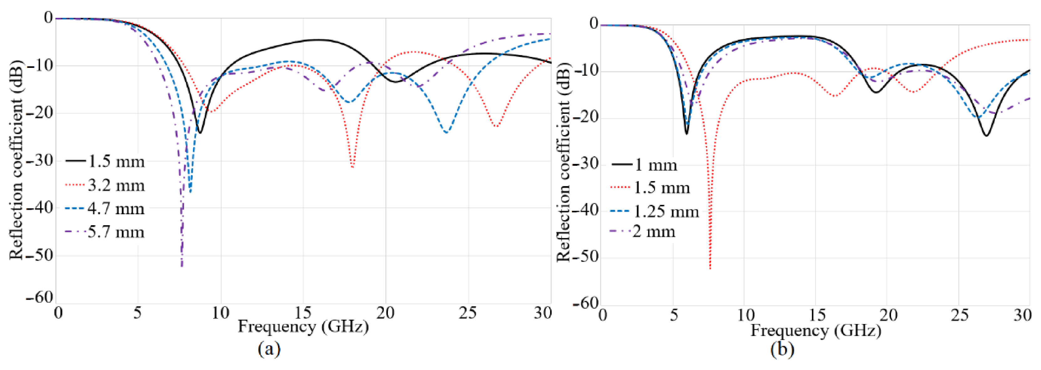
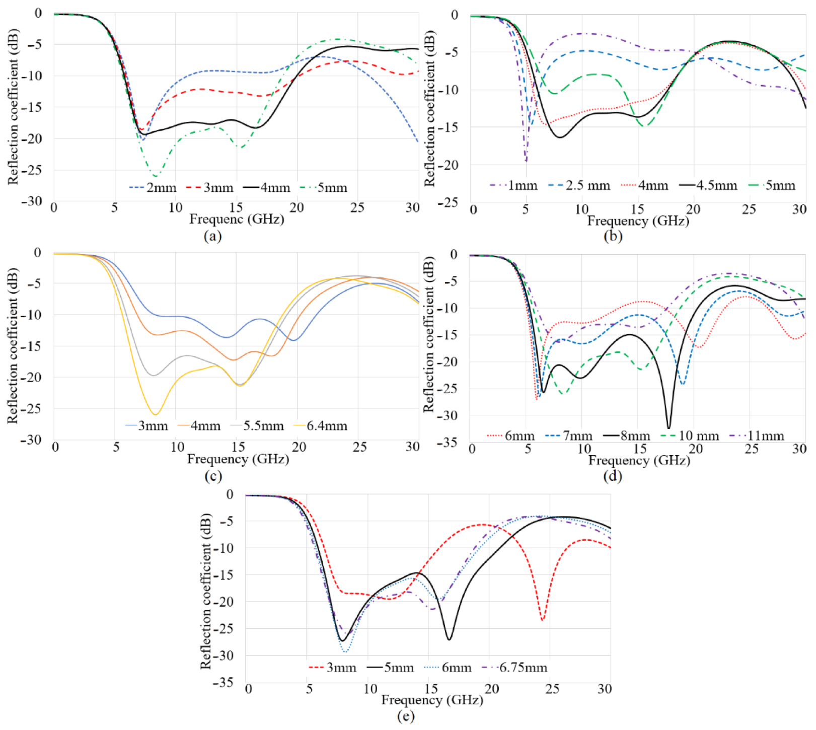
Design Configuration of the Antennas
3. The MIMO Antenna for On-Body and Off-Body Conditions
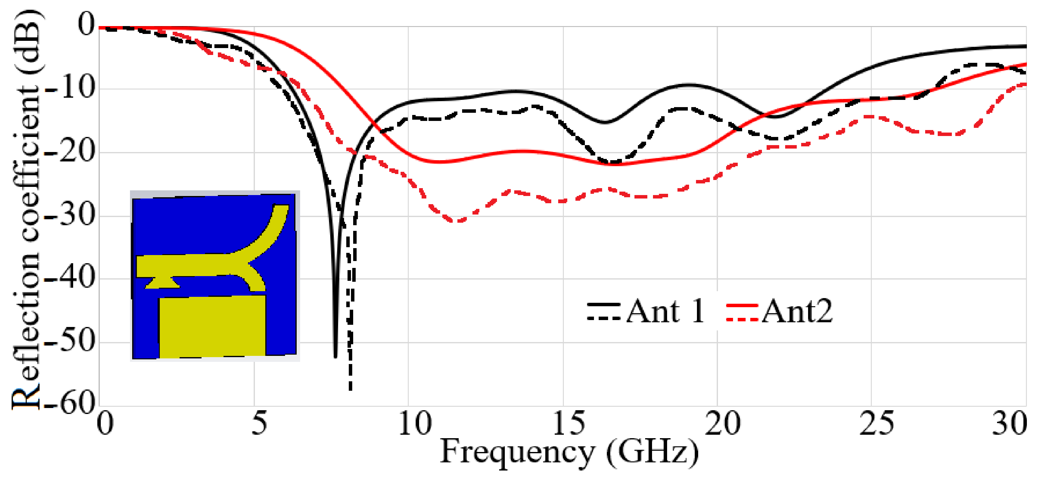
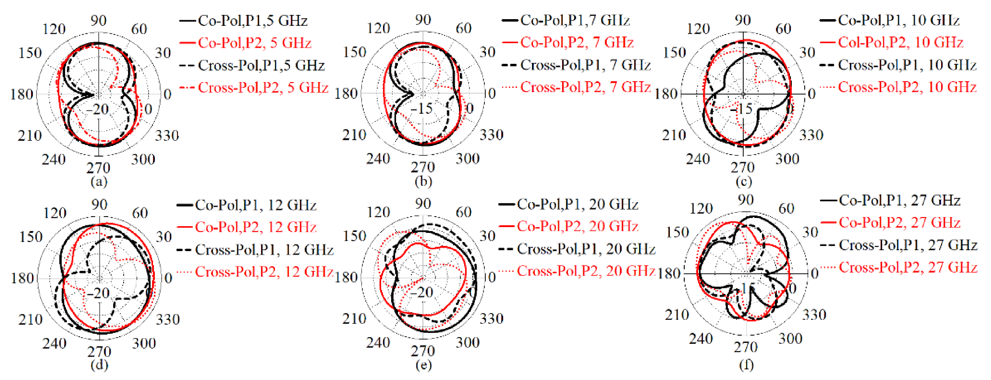
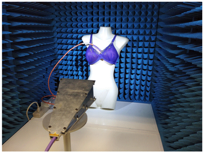
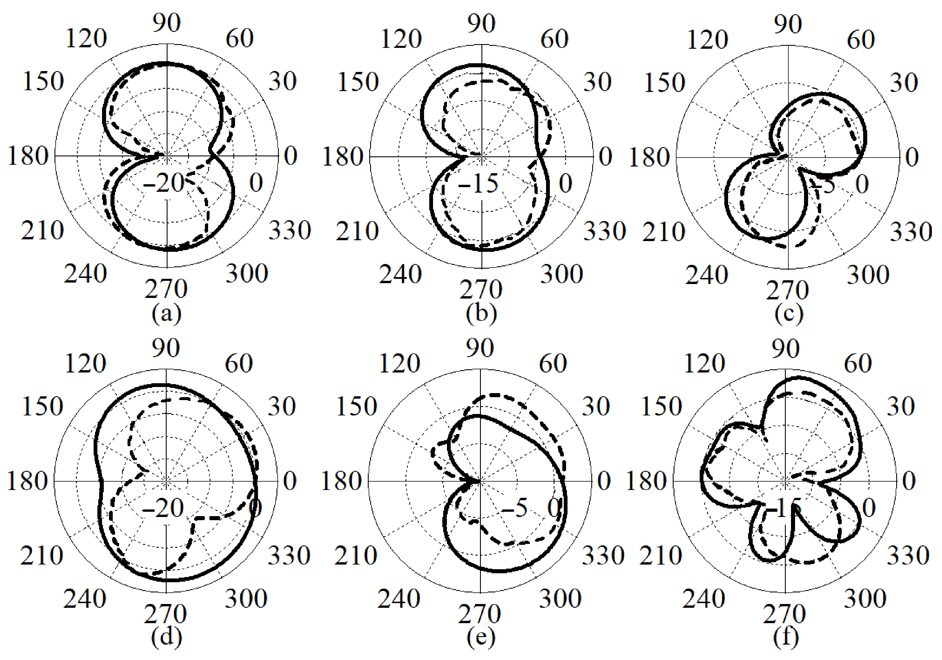
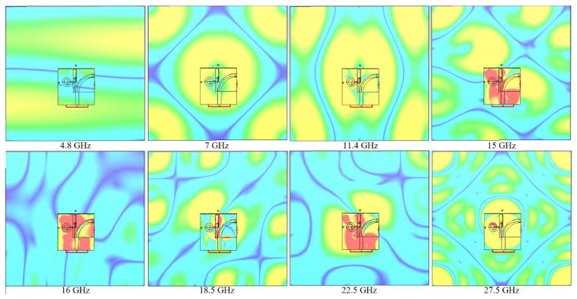
3.1. MIMO Antenna’s Radiation Characteristics
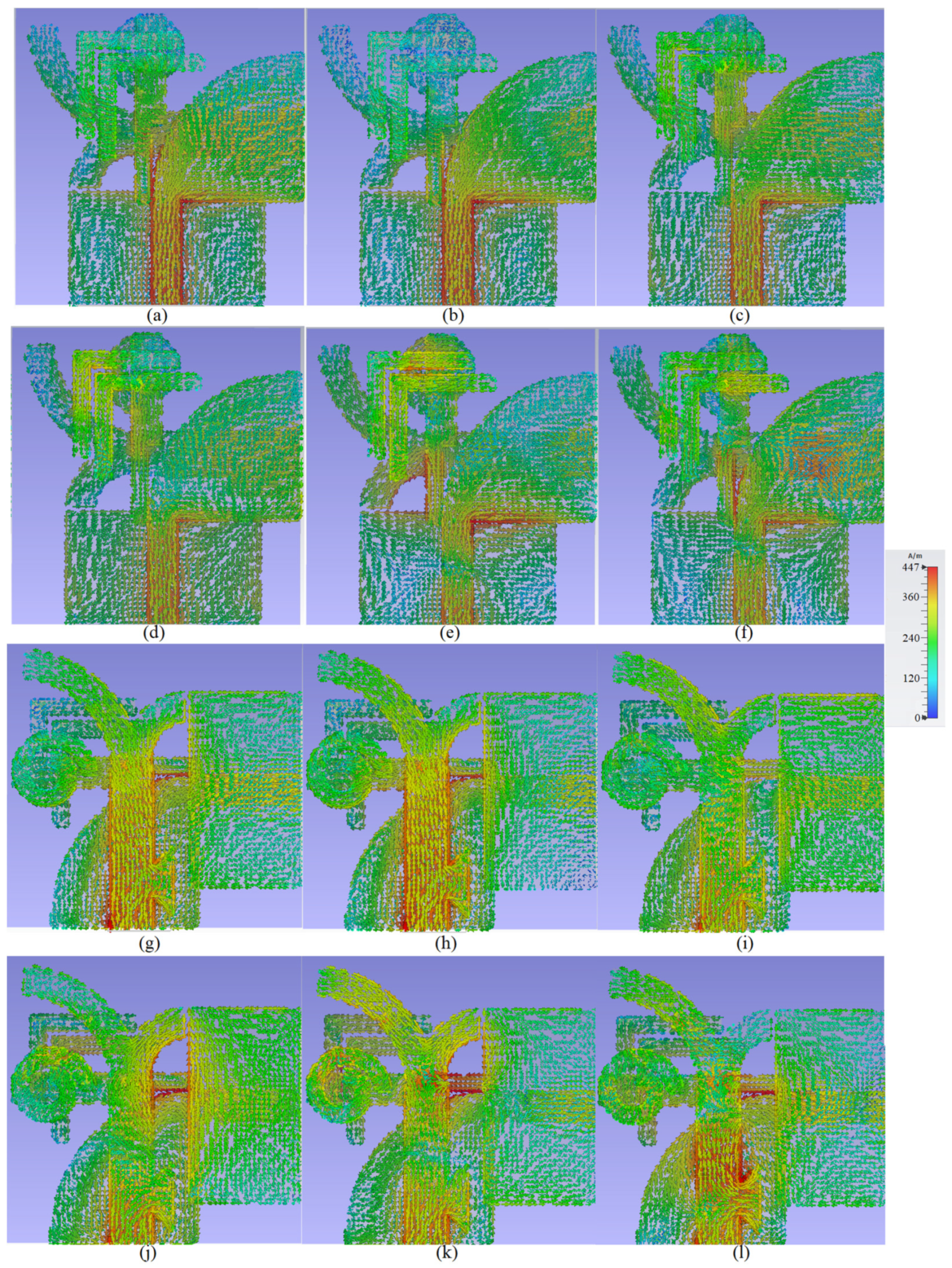
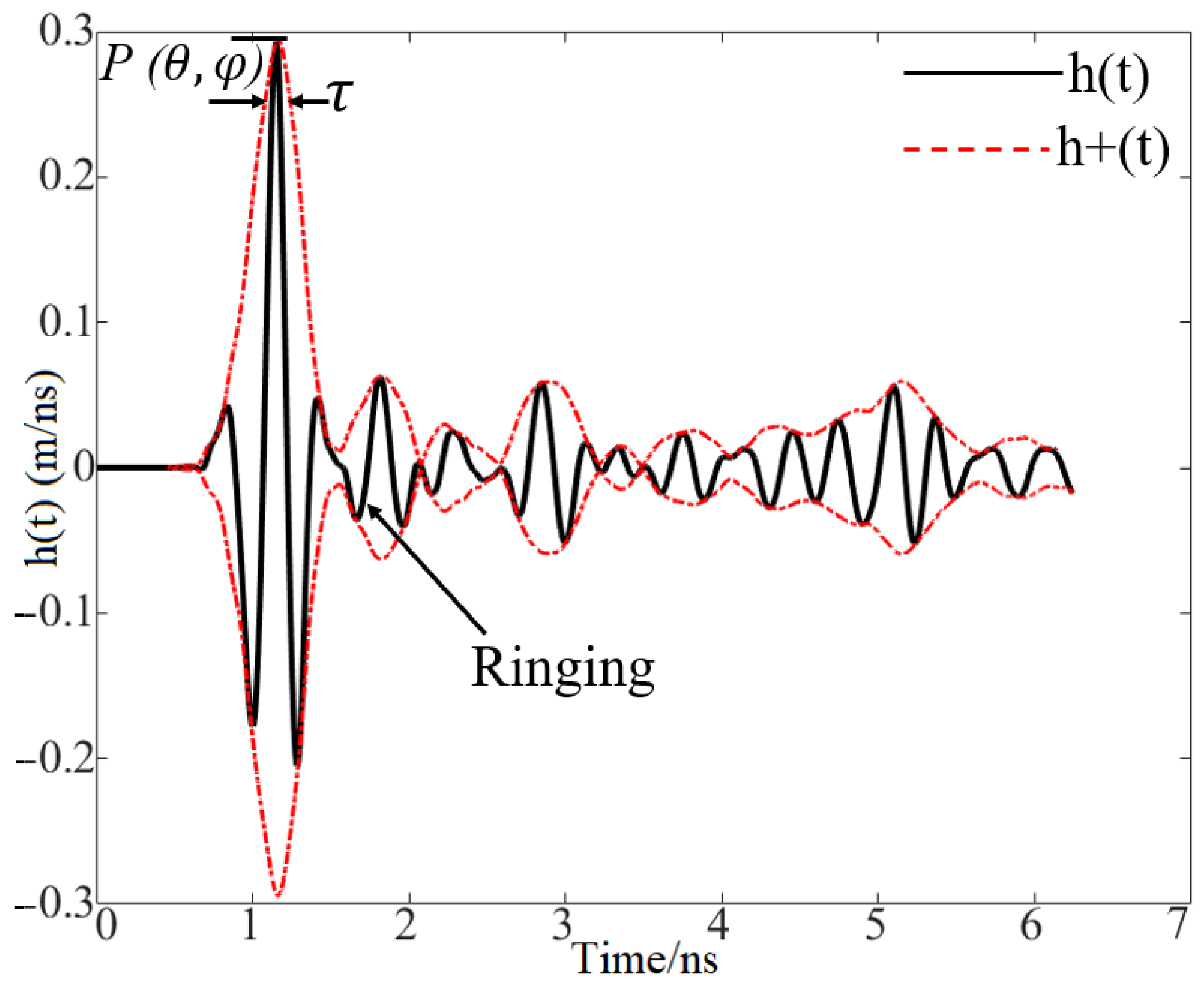
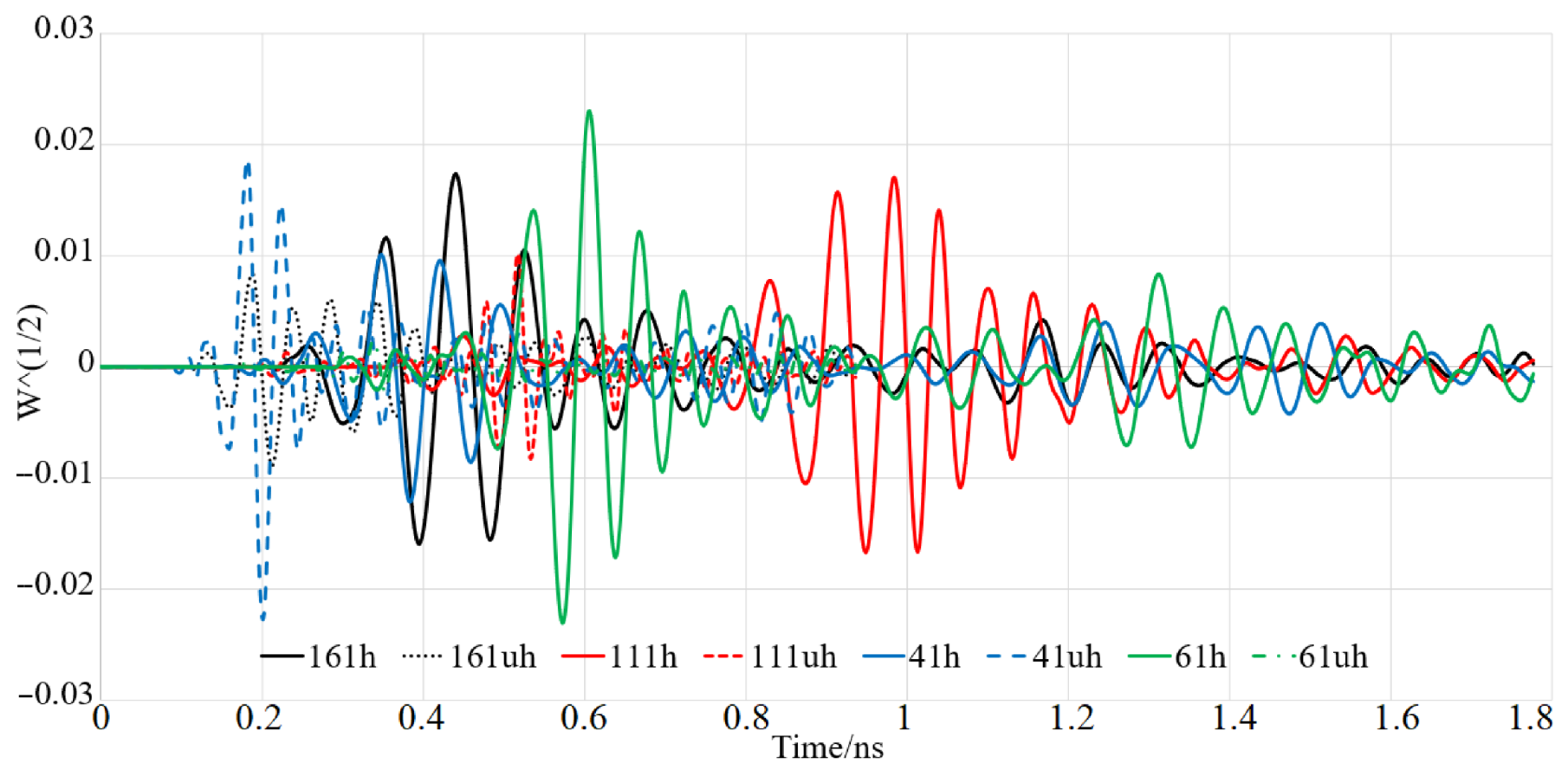
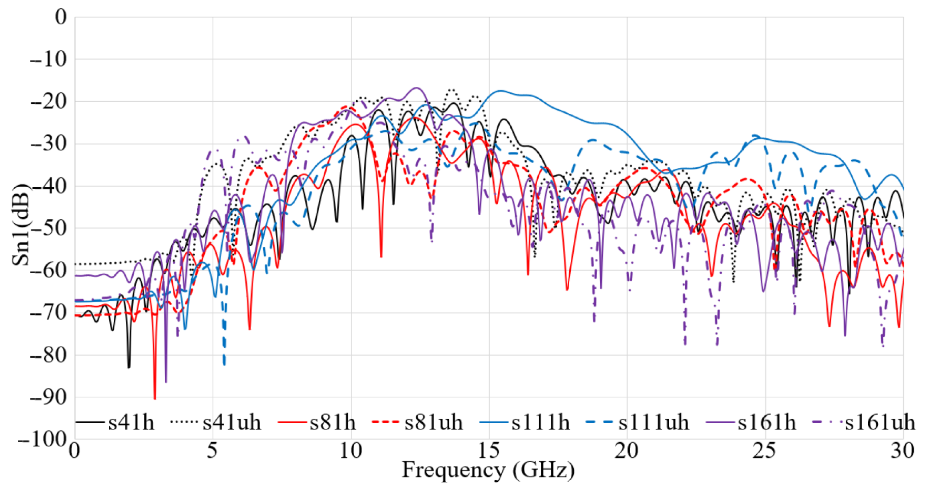
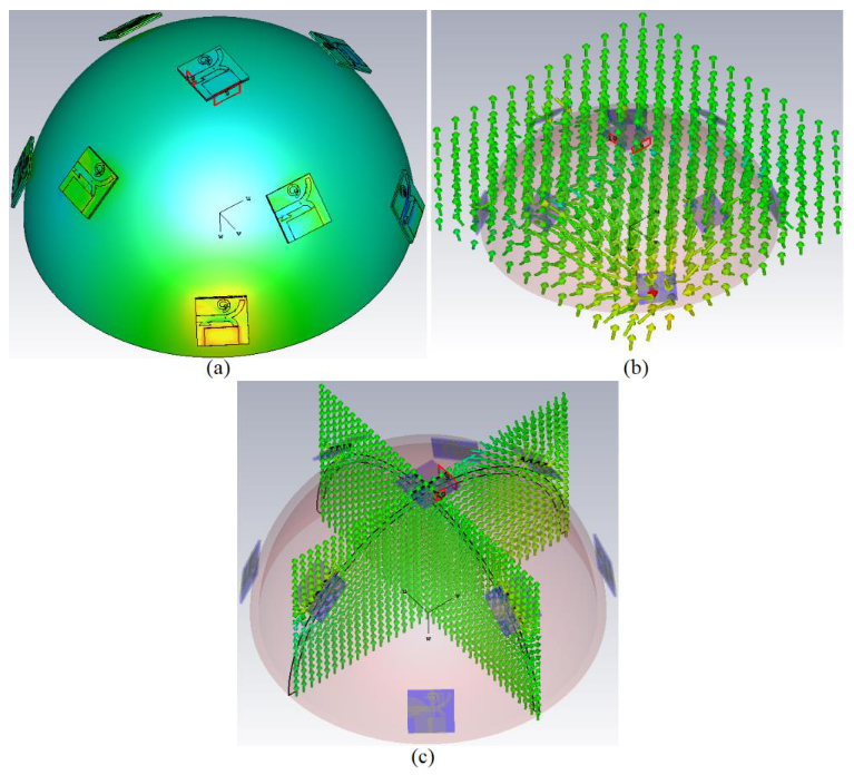
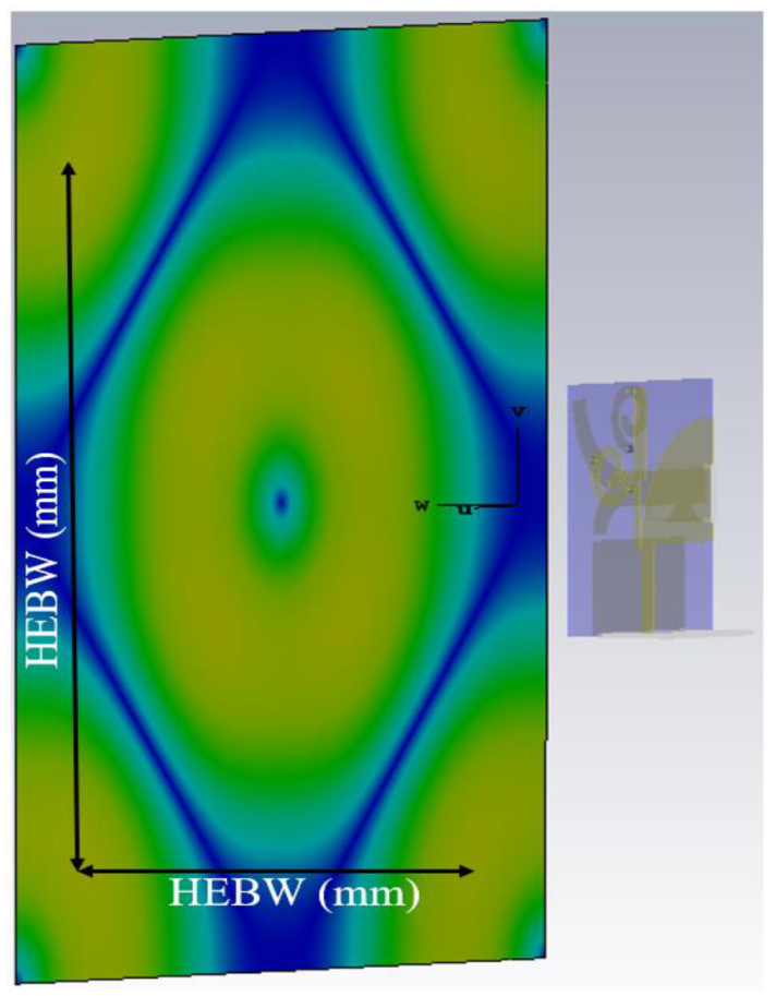
3.2. Near-Field Investigation of the Proposed Antenna for Image Reconstruction
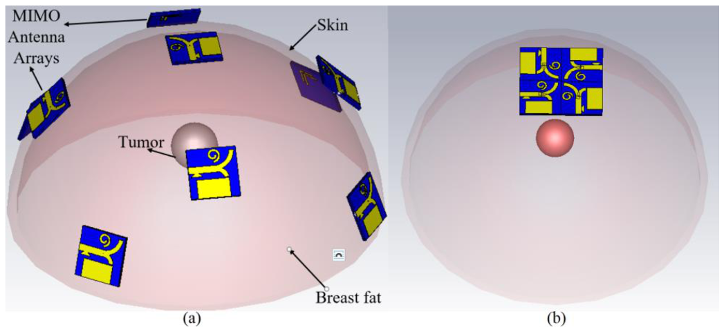
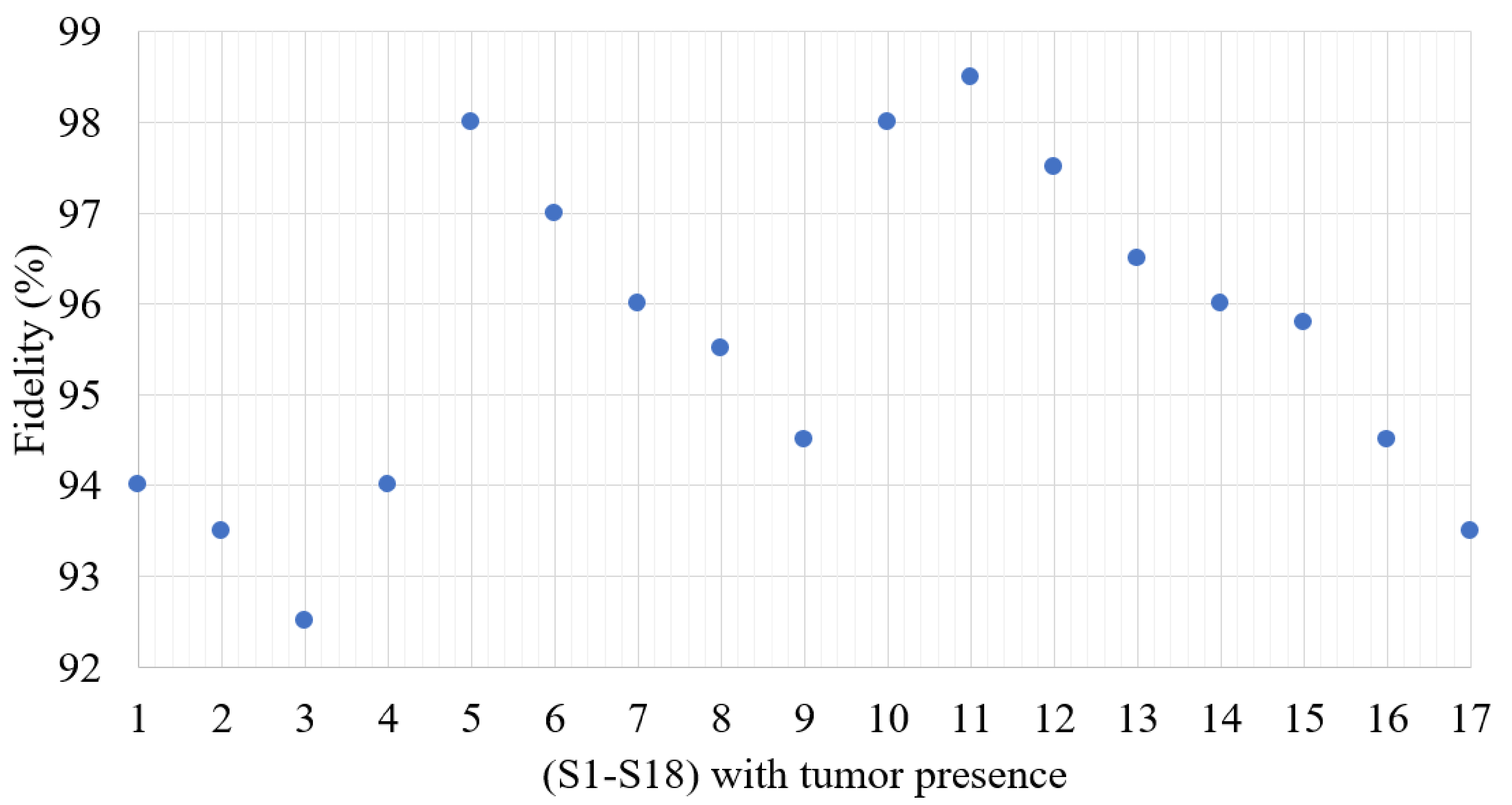
3.3. Image Reconstruction of a Tumour for Various Conditions
4. Conclusions
Author Contributions
Funding
Conflicts of Interest
References
- Alhawari, A.R.H.; Almawgani1, A.H.M.; Hindi, A.T.; Alghamdi, H.; Saeidi, T. Metamaterial-based wearable flexible elliptical UWB antenna for WBAN and breast imaging applications. AIP Adv. 2021, 11, 015128. [Google Scholar] [CrossRef]
- Caldeira, J.M.; Rodrigues, J.J.; Lorenz, P. Toward ubiquitous mobility solutions for body sensor networks on healthcare. IEEE Commun. Mag. 2012, 50, 108–115. [Google Scholar] [CrossRef]
- Badhan, K.; Singh, J. Analysis of Different Performance Parameters of Bodywearable Antenna- A Review. Adv. Wirel. Mob. Commun. 2017, 10, 735–745. [Google Scholar]
- Kirtania, S.G.; Elger, A.W.; Hasan, M.R.; Wisniewska, A.; Sekhar, K.; Karacolak, T.; Sekhar, P.K. Flexible Antennas: A Review. Micromachines 2020, 11, 847. [Google Scholar] [CrossRef]
- Al-Sehemi, A.G.; Al-Ghamdi, A.A.; Dishovsky, N.T.; Atanasov, N.T.; Atanasova, G.L. Flexible and small wearable antenna for wireless body area network applications. J. Electromagn. Waves Appl. JEWA 2017, 31, 1063–1082. [Google Scholar] [CrossRef]
- Chen, S.J.; Ranasinghe, D.C.; Fumeaux, C. A robust snap-on button solution for reconfigurable wearable textile antennas. IEEE Trans. Antennas Propag. 2018, 66, 4541–4551. [Google Scholar] [CrossRef]
- Yan, S.; Vandenbosch, G.A. Radiation pattern-reconfigurable wearable antenna based on metamaterial structure. IEEE Antennas Wirel. Propag. Lett. 2016, 15, 1715–1718. [Google Scholar] [CrossRef]
- Azeez, H.I.; Yang, H.-C.; Chen, W.-S. Wearable triband E-shaped dipole antenna with low SAR for IoT applications. Electronic 2019, 8, 665. [Google Scholar] [CrossRef] [Green Version]
- Al-Ghamdi, A.A.; Al-Hartomy, O.A.; Al-Solamy, F.R.; Dishovsky, N.T.; Atanasov, N.T.; Atanasova, G.L. Enhancing antenna performance and SAR reduction by a conductive composite loaded with carbon-silica hybrid filler. AEU Int. J. Electron. Commun. 2017, 72, 184–191. [Google Scholar] [CrossRef]
- Wang, C.; Yeo, J.C.; Chu, H.; Lim, C.T.; Guo, Y.X. Design of a reconfigurable patch antenna using the movement of liquid metal. IEEE Antennas Wirel. Propag. Lett. 2018, 17, 974–977. [Google Scholar] [CrossRef]
- Tong, X.; Liu, C.; Liu, X.; Guo, H.; Yang, X. Dual-band on-/off-body reconfigurable antenna for wireless body area network (WBAN) applications. Microw. Opt. Technol. Lett. 2018, 60, 945–951. [Google Scholar] [CrossRef]
- Jang, T.; Zhang, C.; Youn, H.; Zhou, J.; Guo, L.J. Semitransparent and Flexible Mechanically Reconfigurable Electrically Small Antennas Based on Tortuous Metallic Micromesh. IEEE Trans. Antennas Propag. 2017, 65, 1. [Google Scholar] [CrossRef]
- Simorangkir, R.B.; Yang, Y.; Esselle, K.P.; Zeb, B.A. A method to realize robust flexible electronically tunable antennas using polymer-embedded conductive fabric. IEEE Trans. Antennas Propag. 2017, 66, 50–58. [Google Scholar] [CrossRef]
- Cai, Y.; Qian, Z.; Cao, W.; Zhang, Y. Research on the half complementary split-ring resonator and its application for designing miniaturized patch antenna. Microw. Opt. Technol. Lett. 2015, 57, 2601–2604. [Google Scholar] [CrossRef]
- Saeidi, T.; Ismail, I.; Alhawari, A.R.; Wen, W.P. Near-field and far-field investigation of miniaturized UWB antenna for imaging of wood. AIP Adv. 2019, 9, 035232. [Google Scholar] [CrossRef] [Green Version]
- Sharony, J. Introduction to Wireless MIMO-Theory and Applications. CEWITA IEEE LI. 2006. Available online: https//ieee.li/pdf/viewgr-aphs/Introd (accessed on 15 November 2006).
- Shoaib, N.; Shoaib, S.; Khattak, R.Y.; Shoaib, I.; Chen, X.; Perwaiz, A. MIMO antennas for smart 5G devices. IEEE Access 2018, 6, 77014–77021. [Google Scholar] [CrossRef]
- Uthansakul, P.; Assanuk, D.; Uthansakul, M. An optimal design of multiple antenna positions on mobile devices based on mutual coupling analysis. Int. J. Antennas Propag. 2011, 2011, 791697. [Google Scholar] [CrossRef] [Green Version]
- Chen, X.; Zhang, S.; Li, Q. A review of mutual coupling in MIMO systems. IEEE Access 2018, 6, 24706–24719. [Google Scholar] [CrossRef]
- Ayman, A. Althuwayb, Low-Interacted Multiple Antenna Systems Based on Metasurface-Inspired Isolation Approach for MIMO Applications. Arab. J. Sci. Eng. 2021. [Google Scholar] [CrossRef]
- Shirkolaei, M.M. Wideband linear microstrip array antenna with high efficiency and low side lobe level. Int. J. RF Microw. Comput. Aided Eng. 2020, e22412. [Google Scholar] [CrossRef]
- Maleki, A.; Oskouei, H.D.; Shirkolaei, M.M. Miniaturized microstrip patch antenna with high inter-port isolation for full duplex communication system. Int. J. RF Microw. Comput. Eng. 2021, 31, e22760. [Google Scholar] [CrossRef]
- Alibakhshikenari, M.; Babaeian, F.; Virdee, B.S.; Aissa, S.; Azpilicueta, L.; See, C.H.; Althuwayb, A.A.; Huynen, I.; Abd-Alhameed, R.A.; Falcone, F.; et al. A Comprehensive Survey on “Various Decoupling Mechanisms with Focus on Metamaterial and Metasurface Principles Applicable to SAR and MIMO Antenna Systems”. IEEE Access 2020, 8, 192965–193004. [Google Scholar] [CrossRef]
- Guo, J.; Liu, F.; Jing, G.; Zhao, L.; Yin, Y.; Huang, G. Mutual coupling reduction of multiple antenna systems. Front. Inform. Technol. Electron. Eng. 2020, 21, 366–376. [Google Scholar] [CrossRef]
- Lin, Y.; Chen, W.; Chen, C.; Liao, C.; Chuang, N.; Chen, H. High-gain MIMO dipole antennas with mechanical steerable main beam for 5G small cell. IEEE Antennas Wirel. Propag. Lett. 2019, 18, 1317–1321. [Google Scholar] [CrossRef]
- Wang, Z.; Du, Y.A. Wideband printed dual-antenna with three neutralization lines for mobile terminals. IEEE Trans. Antennas Propag. 2014, 62, 1495–1500. [Google Scholar] [CrossRef]
- Su, F.S.; Lee, S.W.; Chang, C.T. Printed MIMO-antenna system using neutralization-line technique for wireless USB-dongle applications. IEEE Trans. Antennas Propag. 2012, 60, 456–463. [Google Scholar] [CrossRef]
- Zhao, K.L.; Wu, L.A. Decoupling technique for four-element symmetric arrays with reactively loaded dummy elements. IEEE Trans. Antennas Propag. 2014, 62, 4416–4421. [Google Scholar] [CrossRef]
- Yeung, Y.E.; Wang, L.K. Mode-based beamforming arrays for miniaturized platforms. IEEE Trans. Microw. Theory Tech. 2009, 57, 45–52. [Google Scholar] [CrossRef]
- Wang, T.F.; Li, K.; Eibert, L. Comparison of compact monopole antenna arrays with eigenmode excitation and multiport conjugate matching. IEEE Trans. Antennas Propag. 2013, 61, 4054–4062. [Google Scholar] [CrossRef]
- Andersen, J.; Rasmussen, H. Decoupling and descattering networks for antennas. IEEE Trans. Antennas Propag. 1976, 24, 841–846. [Google Scholar] [CrossRef]
- Ostadrahimi, M.; Noghanian, S.; Shafai, L.; Zakaria, A.; Kaye, C.; LoVetri, J. Investigating double-layer Vivaldi antenna for fixed array field measurement. Int. J. Ultra Wideband Commun. Syst. 2010, 1, 282–290. [Google Scholar] [CrossRef] [Green Version]
- Ostadrahimi, M.; Mojabi, P.; Noghanian, S.; Shafai, L.; Pistorius, S.; LoVetri, J. A novel microwave tomography system based on the scattering probe technique. IEEE Trans. Instrum. Measur. 2012, 61, 379–390. [Google Scholar] [CrossRef]
- Wang, Y.; Yu, Z. A novel symmetric double-slot structure for antipodal Vivaldi antenna to lower cross-polarization level. IEEE Trans. Antennas Propag. 2017, 65, 5599–5604. [Google Scholar] [CrossRef]
- Moosazadeh, M.; Kharkovsky, S. A compact high-gain and front-to-back ratio elliptically tapered antipodal Vivaldi antenna with trapezoid-shaped dielectric lens. IEEE Antennas Wirel. Propag. Lett. 2016, 15, 552–555. [Google Scholar] [CrossRef]
- Chen, L.; Lei, Z.; Yang, R.; Fan, J.; Shi, X. A broadband artificial material for gain enhancement of antipodal tapered slot antenna. IEEE Trans. Antennas Propag. 2015, 63, 395–400. [Google Scholar] [CrossRef]
- Zhang, J.; Zhang, X.; Xiao, S. Antipodal Vivaldi antenna to detect uhf signals that leaked out of the joint of a transformer. Int. J. Antennas Propag. 2017, 9627649. [Google Scholar] [CrossRef] [Green Version]
- Garg, R.; Bhartia, P.; Bahl, I.; Ittipiboon, A. Microstrip Antenna Design Handbook; Artech House INC: Norwood, MA, USA, 2001. [Google Scholar]
- Saeidi, T.; Ismail, I.; Noghanian, S.; Alhawari, A.R.H.; Abbasi, Q.H.; Imran, M.A.; Zeain, M.Y.; Ali, S.M. High Gain Triple-Band Metamaterial-Based Antipodal Vivaldi MIMO Antenna for 5G Communications. Micromachines 2021, 12, 250. [Google Scholar] [CrossRef]
- Wang, L.; Huang, B. Design of Ultra-WidebandMIMO Antenna for Breast Tumor Detection. Int. J. Antennas Propag. 2012, 2012, 180158. [Google Scholar] [CrossRef]
- Chen, Y.; Gunawan, E.; Low, K.S.; Wang, S.C.; Kim, Y.; Soh, C.B. Pulse design for time reversal method as applied to ultrawideband microwave breast cancer detection: A twodimensional analysis. IEEE Trans. Antennas Propag. 2007, 55, 194–204. [Google Scholar] [CrossRef]
- Davis, S.K.; Van Veen, B.D.; Hagness, S.C.; Kelcz, F. Breast tumor characterization based on ultrawideband microwave backscatter. IEEE Trans. Biomed. Eng. 2008, 55, 237–246. [Google Scholar] [CrossRef]
- Hilger, I.; Geyer, C.; Rimkus, G.; Helbig, M.; Sachs, J.; Schwarz, U.; Hein, M.A.; Kaiser, W.A. Could we use UWB sensing for breast cancer detection? In Proceedings of the Fourth European Conference on Antennas and Propagation, Barcelona, Spain, 12–16 April 2010; IEEE: Piscataway, NJ, USA, 2010; pp. 1–4. [Google Scholar]
- Daniel, O.T.; Yuanjin, Z.; Zhiping, L. Design and experimental investigation of UWB microwave imaging via MIMO beamforming. In Proceedings of the IEEE International Conference on Ultra-Wideband (ICUWB ’10), Nanjing, China, 20–23 September 2010; IEEE: Piscataway, NJ, USA, 2010; pp. 851–854. [Google Scholar]
- Davis, S.K.; Tandradinata, H.; Hagness, S.C.; Van Veen, B.D. Ultrawideband microwave breast cancer detection: A detection-theoretic approach using the generalized likelihood ratio test. IEEE Trans. Biomed. Eng. 2005, 52, 1237–1250. [Google Scholar] [CrossRef]
- Bliss, D.W.; Forsythe, K.W. MIMO Radar medical imaging: Self-interference mitigation for breast tumor detection. In Proceedings of the 40th Asilomar Conference on Signals, Systems, and Computers (ACSSC ’06), Pacific Grove, CA, USA, 29 October–1 November 2006; IEEE: Piscataway, NJ, USA, 2006; pp. 1558–1562. [Google Scholar]
- Muhajr, A.B.; Mahdi, J.; Khadhim, M.A. Design of Ultra-Wideband MIMO Antenna for Breast Tumor Detection. In IOP Conference Series: Materials Science and Engineering; IOP Publishing: Bristol, UK, 2020; Volume 881, p. 012111. [Google Scholar] [CrossRef]
- Saxena, G.; Jain, P.; Awasthi, Y.K. High Diversity Gain MIMO-Antenna for UWB Application with WLAN Notch Band Characteristic Including Human Interface Devices. Wirel. Pers. Commun. 2019, 112, 105–121. [Google Scholar] [CrossRef]
- Hu, Z.; Zeng, Z.; Wang, K.; Feng, W.; Zhang, J.; Lu, Q.; Kang, X. Design and Analysis of a UWB MIMO Radar System with Miniaturized Vivaldi Antenna forThrough-Wall Imaging. Remote Sens. 2019, 11, 1867. [Google Scholar] [CrossRef] [Green Version]
- Yang, B.; Zhuge, X.; Yarovoy, A.G.; Ligthart, L.P. UWB MIMO Antenna Array Topology Design Using PSO for Through Dress Near-field Imaging. In Proceedings of the 38th European Microwave Conference, Delft, The Netherlands, 31 October 2006; IEEE: Piscataway, NJ, USA, 2008. [Google Scholar]
- Mahmood, S.N.; Ishak, A.J.; Saeidi, T.; Soh, A.C.; Jalal, A.; Imran, M.A.; Abbasi, Q.H. Full Ground Ultra-Wideband Wearable Textile Antenna for Breast Cancer and Wireless Body Area Network Applications. Micromachines 2021, 12, 322. [Google Scholar] [CrossRef]
- Alam, M.; Misran, N.; Yatim, B.; Islam, M.T. Development of Electromagnetic Band Gap Structures in the Perspective of Microstrip Antenna Design. Int. J. Antennas Propag. 2013, 2013, 22. [Google Scholar] [CrossRef]
- Nassar, I.T.; Weller, T.M. A novel method for improving antipodal Vivaldi antenna performance. IEEE Trans. Antennas Propag. 2015, 63, 3321–3324. [Google Scholar] [CrossRef]
- Amiri, M.; Tofigh, F.; Ghafoorzadeh-Yazdi, A.; Abolhasan, M. Exponential antipodal Vivaldi antenna with exponential dielectric lens. IEEE Antennas Wirel. Propag. Lett. 2017, 16, 1792–1795. [Google Scholar] [CrossRef]
- Ahadi, M.; Isa, M.B.M.; Saripan, M.I.B.; Hasan, W.Z.W. Square monopole antenna for microwave imaging, design and characterisation. IET Microw. Antennas Propag. 2015, 9, 49–57. [Google Scholar] [CrossRef]
- Eichenberger, J.; Yetisir, E.; Ghalichechian, N. High-Gain Antipodal Vivaldi Antenna with Pseudoelement and Notched Tapered Slot Operating at (2.5 to 57) GHz. IEEE Trans. Antennas Propag. 2019, 67, 4357–4366. [Google Scholar] [CrossRef]
- Islam, M.M.; Islam, M.T.; Samsuzzaman, M.; Faruque, M.R. Compact metamaterial antenna for UWB applications. Electron. Lett. 2015, 51, 1222–1224. [Google Scholar] [CrossRef]
- Li, Y.; Li, W.; Yu, W. A Switchable UWB Slot Antenna using SIS-HSIR and SIS-SIR for Multi-Mode Wireless Communications Applications. ACES J. 2012, 27, 4. [Google Scholar]
- Li, Y.; Li, W.; Ye, Q. A Reconfigurable Triple-Notch-Band Antenna Integrated with Defected Microstrip Structure Band-Stop Filter for Ultra-Wideband Cognitive Radio Applications. Int. J. Antennas Propag. 2013, 2013, 472645. [Google Scholar] [CrossRef]
- Liu, F.; Guo, J.; Zhao, L.; Huang, G.; Li, Y.; Yin, Y. Ceramic Superstrate-based Decoupling Method for Two Closely Packed Antennas with Cross-Polarization Suppression. IEEE Trans. Antennas Propag. 2020, 69, 1751–1756. [Google Scholar] [CrossRef]
- Jiang, J.; Xia, Y.; Li, Y. High Isolated X-Band MIMO Array Using Novel Wheel-Like Metamaterial Decoupling Structure. Aces J. 2019, 34, 12. [Google Scholar]
- Luo, S.; Li, Y.; Xia, Y.; Zhang, L. A Low Mutual Coupling Antenna Array with Gain Enhancement Using Metamaterial Loading and Neutralization Line Structure. Aces J. 2019, 34, 3. [Google Scholar]
- Li, Y.; Li, W.; Yu, W. A Multi-Band/UWB MIMO/Diversity Antenna with an Enhanced Isolation Using Radial Stub Loaded Resonator. Aces J. 2013, 28, 1. [Google Scholar]
- Saeidi, T.; Ismail, I.; Mahmood, S.N.; Alani, S.; Alhawari, A.R. Microwave imaging of voids in oil palm trunk applying UWB antenna and robust time-reversal algorithm. J. Sens. 2020, 2020, 8895737. [Google Scholar] [CrossRef]
- Simorangkir, R.B.; Kiourti, A.; Esselle, K.P. UWB wearable antenna with a full ground plane based on PDMS-embedded conductive fabric. IEEE Antennas Wirel. Propag. Lett. 2018, 17, 493–496. [Google Scholar] [CrossRef]
- Gharbi, M.; Martinez-Estrada, M.; Fernández-García, R.; Ahyoud, S.; Gil, I. A novel ultra-wide band wearable antenna under different bending conditions for electronic-textile applications. J. Text. Inst. 2021, 112, 437–443. [Google Scholar] [CrossRef]
- Sugumaran, B.; Balasubramanian, R.; Palaniswamy, S.K. Reduced specific absorption rate compact flexible monopole antenna system for smart wearable wireless communications. Eng. Sci. Technol. Int. J. 2021, 20, 682–693. [Google Scholar]
- Yadav, A.; Singh, V.K.; Bhoi, A.K.; Marques, G.; Garcia-Zapirain, B.; Torre Díez, I. Wireless Body Area Networks: UWB Wearable Textile Antenna for Telemedicine and Mobile Health Systems. Micromachines 2020, 11, 558. [Google Scholar] [CrossRef] [PubMed]
- Kumar, S.; Lee, G.H.; Kim, D.H.; Mohyuddin, W.; Choi, H.C.; Kim, K.W. A compact four-port UWB MIMO antenna with connected ground and wide axial ratio bandwidth. Int. J. Microw. Wirel. Technol. 2019, 12, 75–85. [Google Scholar] [CrossRef]
- Yalduz, H.; Tabaru, T.E.; Kilic, V.T.; Turkmen, M. Design and analysis of low profile and low SAR full-textile UWB wearable antenna with metamaterial for WBAN applications. Int. J. Electron. Commun. 2020, 126, 153465. [Google Scholar] [CrossRef]
- Altaf, A.; Iqbal, A.; Smida, A.; Smida, J.; Althuwayb, A.A.; Hassank Kiani, S.; Alibakhshikenari, M.; Falcone, F.; Limiti, E. Isolation Improvement in UWB-MIMO Antenna System Using Slotted Stub. Electronics 2020, 9, 1582. [Google Scholar] [CrossRef]
- Sampath, R.; Selvan, K.T. Compact hybrid Sierpinski Koch fractal UWB MIMO antenna with pattern diversity. Int. J. RF Microw. Comput. Aided Eng. 2019, e22017. [Google Scholar] [CrossRef]
- Addepalli, T.; Anitha, V.R. A Very Compact and Closely Spaced Circular Shaped UWB MIMO Antenna with Improved Isolation. Int. J. Electron. Commun. 2019. [Google Scholar] [CrossRef]
- Gurjar, R.; Upadhyay, D.K.; Kanaujia, B.K.; Kumar, A. A compact modified sierpinski carpet fractal UWB MIMO antenna with square-shaped funnel-like ground stub. Int. J. Electron. Commun. (AEÜ) 2020, 117, 153126. [Google Scholar] [CrossRef]
- Dey, A.B.; Pattanayak, S.S.; Mitra, D.; Arif, W. Investigation and design of enhanced decoupled UWB MIMO antenna for wearable applications. Microw. Opt. Technol. Lett. 2020, 1–17. [Google Scholar] [CrossRef]
- Alibakhshikenari, M.; Virdee, B.S.; Shukla, P.; Parchin, N.O.; Azpilicueta, L.; See, C.H.; Abd-Alhameed, R.A.; Falcone, F.; Huynen, I.; Denidni, T.A.; et al. Metamaterial-Inspired Antenna Array for Application in Microwave Breast Imaging Systems for Tumor Detection. IEEE Access 2020, 8, 174667–174678. [Google Scholar] [CrossRef]


| Param (mm) | Dimensions | Param (mm) | Dimensions | Param (mm) | Dimensions |
|---|---|---|---|---|---|
| 11 | 1 | 7 | |||
| 11 | 1.5 | 4 | |||
| 1 | 1.03 | , | 1, 0.5 | ||
| 3.8 | 2.5 | , | 0.25, 0.5 | ||
| 3.5 | 1.75, 1 | 3.75 | |||
| 6.88 | 3.92 | 5.7 | |||
| 3.75 |
| Parameter | ||
|---|---|---|
| Breast fat | 5.62 | 0.1301 ± 0.068 |
| Skin | 43 | 0.0007 |
| Tumour | 57 | 2.7 ± 0.07 |
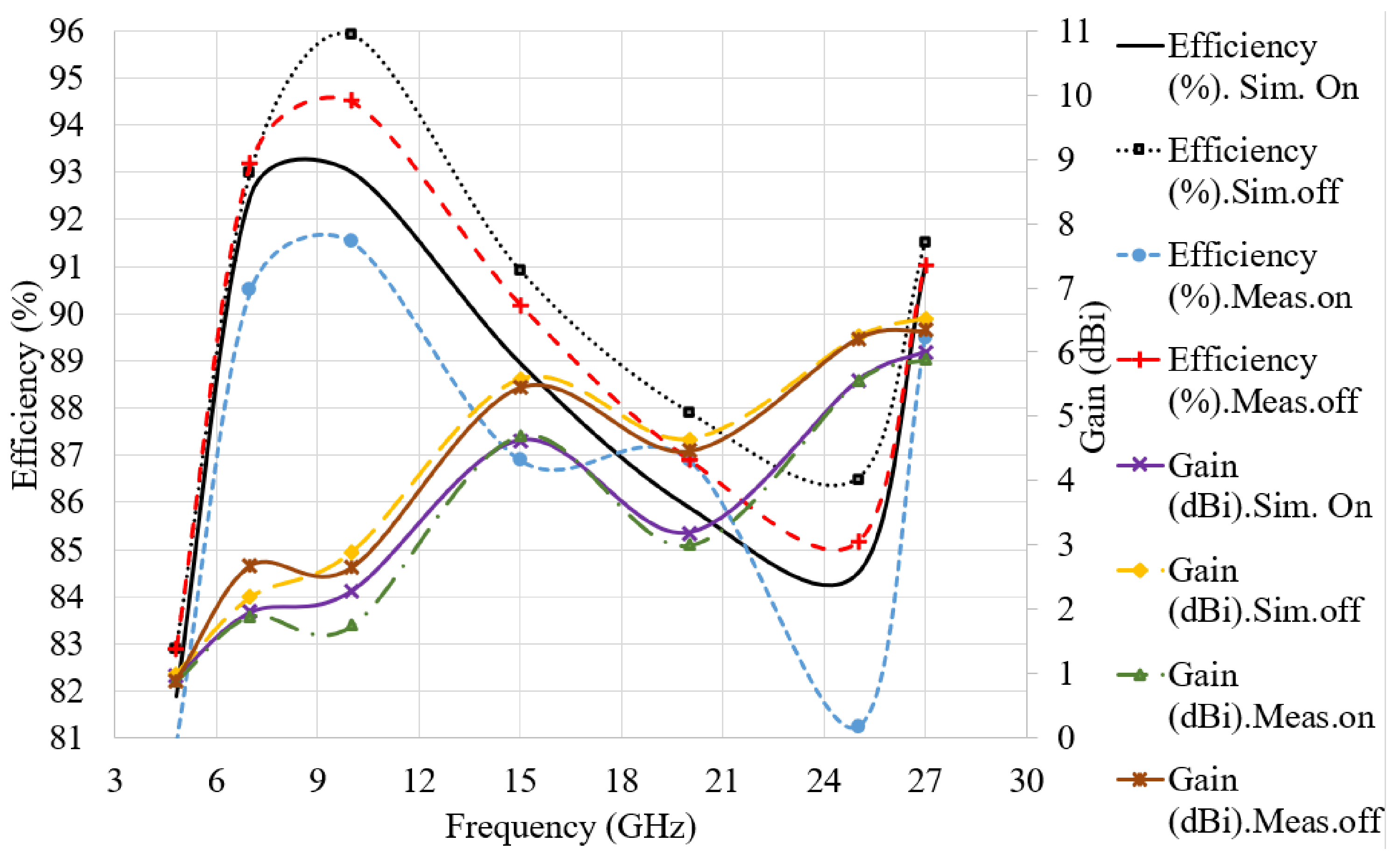
| Parameters fr (GHz) | Eff (%) Sim. On | Gain (dBi) Sim. On | Eff (%) Sim. off | Gain (dBi) Sim. off | Eff (%) Meas. on | Gain (dBi) Meas. on | Eff (%) Meas. off | Gain (dBi) Meas. off |
|---|---|---|---|---|---|---|---|---|
| 4.8 | 81.90 | 0.57 | 82.95 | 0.91 | 80.70 | 0.49 | 82.90 | 0.90 |
| 7 | 92.50 | 0.96 | 93.00 | 1.69 | 90.00 | 0.90 | 92.00 | 1.68 |
| 10 | 93.00 | 1.68 | 95.90 | 2.73 | 91.53 | 1.75 | 94.19 | 2.65 |
| 15 | 88.95 | 4.66 | 90.80 | 5.58 | 86.91 | 4.70 | 90.77 | 5.45 |
| 20 | 85.27 | 3.27 | 87.50 | 4.65 | 84.36 | 3.02 | 86.58 | 4.46 |
| 25 | 81.56 | 5.56 | 84.00 | 6.24 | 80.47 | 5.55 | 84.25 | 6.01 |
| 27 | 89.00 | 6 | 91.25 | 6.53 | 89.00 | 5.89 | 91.16 | 6.33 |
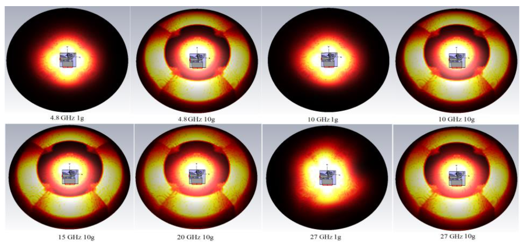
| 4.8 GHz (1 g, 10 g) | 10 GHz (1 g, 10 g) | 15 GHz (1 g, 10 g) | 27 GHz (1 g, 10 g) | |
|---|---|---|---|---|
| Values (W/Kg) | 0.115, 0.671 | 0.71, 1.93 | 1.79, 1.41 | 2.01, 0.984 |
| Ref No. | Dimensions (mm) | BW (GHz) | Max Efficiency (%) | Max Gain (dBi) | SAR (W/Kg) | |
|---|---|---|---|---|---|---|
| [66] | 0.31 × 0.31 | 3.1 | 8.2 | 60.00 | 4.00 | - |
| [67] | 1.27 × 1.27 | 2.075 | 8.3 | - | 7.76 | 0.164 |
| [68] | 0.24 × 0.24 | 2.96 | 0.55 | - | 5.47 | 1.68 |
| [69] | 0.46 × 0.46 | 3.1 | 7.9 | - | 3.50 | - |
| [70] | 0.65 × 0.65 | 4.55 | 8.85 | - | 6.00 | 0.067 |
| [71] | 0.22 × 0.32 | 2 | 11.7 | - | 4.30 | - |
| [72] | 0.16 × 0.33 | 2.5 | 8.5 | - | - | - |
| [73] | 0.15 × 0.24 | 2.82 | 11.63 | 91.70 | 6.86 | - |
| [74] | 0.24 × 0.30 | 3 | 9.6 | - | 5.20 | - |
| [75] | 0.30 × 0.21 | 1.83 | 11.99 | - | 4.21 | 0.335 |
| [76] | 22 × 22 | 2 | 10 | <85 | 11.2 | N/A |
| Proposed | 0.38 × 0.38 | 4.8 | 25.2 | 96.00 | 5.72 | 0.115 |
| Ref No. | Application | Feeding | Radiation | |
|---|---|---|---|---|
| [66] | Wearables | Felt (1.2, 0.7) | TL and partial GND | Nearly omni |
| [67] | ISM Wearables | Jeans (1.7, 1) | TL and partial GND, FSS | omni |
| [68] | Wearable UWB, mobile health | Jeans (1.7, 1) | TL and partial GND | Omni and Quasi-omni |
| [69] | UWB communication | FR4 (4.3, 0.87) | TL and a slotted GND | Nearly omni |
| [70] | Wearables, WBAN | Felt (1.4, 1) | TL and partial GND | Broad side |
| [71] | UWB communication | FR4 (4.4, 1.6) | TL and stepped GND | Nearly bidirectional |
| [72] | MIMO packaging application | FR4 (4.3, 1.6) | TL and stepped GND | Nearly omni |
| [73] | MIMO and UWB communication | FR4 (4.4, 1.6) | TL and defected partial GND | Omni and bidirectional |
| [74] | UWB applications | FR4 (4.3, 0.8) | TL and partial GND | Omni |
| [75] | Wearables | Jeans (2, 1.59) | Partially etched GND | Unidirectional |
| Proposed | Wearable, ISM, MIMO and UWB communication | Felt (1.8, 09), Denim (1.2, 0.5) | TL and partial GND | Directional |
Publisher’s Note: MDPI stays neutral with regard to jurisdictional claims in published maps and institutional affiliations. |
© 2021 by the authors. Licensee MDPI, Basel, Switzerland. This article is an open access article distributed under the terms and conditions of the Creative Commons Attribution (CC BY) license (https://creativecommons.org/licenses/by/4.0/).
Share and Cite
Mahmood, S.N.; Ishak, A.J.; Jalal, A.; Saeidi, T.; Shafie, S.; Soh, A.C.; Imran, M.A.; Abbasi, Q.H. A Bra Monitoring System Using a Miniaturized Wearable Ultra-Wideband MIMO Antenna for Breast Cancer Imaging. Electronics 2021, 10, 2563. https://doi.org/10.3390/electronics10212563
Mahmood SN, Ishak AJ, Jalal A, Saeidi T, Shafie S, Soh AC, Imran MA, Abbasi QH. A Bra Monitoring System Using a Miniaturized Wearable Ultra-Wideband MIMO Antenna for Breast Cancer Imaging. Electronics. 2021; 10(21):2563. https://doi.org/10.3390/electronics10212563
Chicago/Turabian StyleMahmood, Sarmad Nozad, Asnor Juraiza Ishak, Ali Jalal, Tale Saeidi, Suhaidi Shafie, Azura Che Soh, Muhammad Ali Imran, and Qammer H. Abbasi. 2021. "A Bra Monitoring System Using a Miniaturized Wearable Ultra-Wideband MIMO Antenna for Breast Cancer Imaging" Electronics 10, no. 21: 2563. https://doi.org/10.3390/electronics10212563
APA StyleMahmood, S. N., Ishak, A. J., Jalal, A., Saeidi, T., Shafie, S., Soh, A. C., Imran, M. A., & Abbasi, Q. H. (2021). A Bra Monitoring System Using a Miniaturized Wearable Ultra-Wideband MIMO Antenna for Breast Cancer Imaging. Electronics, 10(21), 2563. https://doi.org/10.3390/electronics10212563