Abstract
A new type of spoof surface plasmon polaritons (SSPPs) developed from conventional substrate integrated waveguide (SIW) using ring slots and vias is proposed in this paper. The asymptotic frequency and lower cutoff frequency of the SSPP structure can be easily tuned by changing the width of SIW walls and radius of the ring slot, respectively. A trapezoidal microstrip line and a small ring slot are used for the efficient mode conversion to smoothly transit from microstrip line to the proposed SSPP structure. The presented SSPPs have a flat bandpass filtering response with adjustable center frequency and bandwidth. In order to better verify the transmission and cutoff characteristics, two bandpass filters using the proposed SSPPs with relative bandwidths of 61.7% and 76.4%, respectively, are fabricated and measured. Good agreement between the simulations and measurements verifies the proposed design idea.
1. Introduction
Surface plasmon polaritons (SPPs) are surface electromagnetic waves in the optical frequency band that propagate along the metal-dielectric interface but decay rapidly in the vertical direction []. In 2004, Pendry et al. proposed a periodic metal hole array that supports SPP-like surface mode having strong field confinement in the lower frequencies, which was named as designer or spoof SPPs []. Consequently, the theory and application of spoof SPPs (SSPPs) have been further explored at microwave and TeraHertz frequencies in recent years. Various planar ultra-thin SSPPs have been proposed for the design of bandpass filters (BPFs) [,,,,], frequency splitters [] and leaky wave antennas [,].
Compared with the traditional microwave filters, such as coupled line filters [,,,], waveguide filters [,,], the SSPP based filters have the advantages of easily tunable bandwidth and fast design period through observing the dispersion characteristics of the SSPP unit cell, which are also a good candidate for the 5G or internet of thing applications []. However, the conventional ultra-thin SSPPs are generally constructed by corrugated strip lines, which are all open structures. Thus, the radiation loss and mutual coupling with other closely-spaced transmission lines or circuits are unavoidable. On the other hand, a balun has to be added if the traditional SSPP structures are applied in the BPF designs [,] due to the intrinsic low-pass filtering characteristics of SSPPs [,].
Substrate integrated waveguide (SIW) has been widely applied in the design of microwave circuits and antennas for its advantages of low loss, low profile, low crosstalk and so on [,,]. In this paper, based on the traditional SIW, a new type of SSPP structure is proposed through loading ring slots and vias. The bandpass filtering response can be obtained with the help of SIW’s high-pass characteristics, and the bandwidth can be easily tuned without increasing the size of the waveguide. Two BPFs using the proposed SSPPs with different bandwidths are fabricated and measured to validate the design idea.
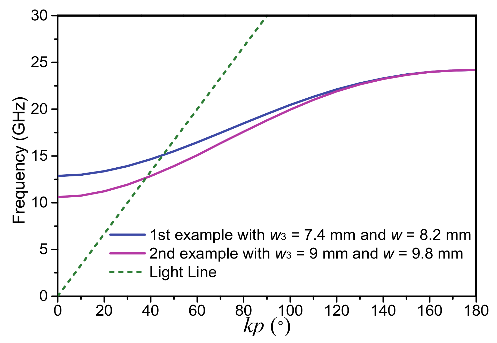
2. Analysis of SSPP Waveguide Developed from SIW
The proposed SSPP structure based on SIW is shown in Figure 1, where the metal film has a thickness of 0.035 mm and is denoted in yellow. It consists of a conventional SIW with the periodic array of ring slots on the top metal layer and via holes. The via hole connected to the ground of the bottom metal layer is located at the center of the ring slot for each SSPP unit cell. The dielectric substrate sandwiched between the top and bottom metal layers is F4B using PTFE material from Wangling, which has a relative dielectric constant of 2.65, loss tangent of 0.0015, and a thickness of 0.5 mm. To further understand the properties of the proposed SSPP structure, its dispersion curves are analyzed. The parameters of the SSPP unit cell are set as follows: w = 8.2 mm, p = 2.5 mm, g = 0.85 mm, r = 1 mm, s = 0.15 mm, dvia_1 = dvia_2 = 0.5 mm.
Figure 1.
Schematic of the proposed SSPP structure.
The dispersion curves of the proposed SSPP structure with different values of parameters w, r, and s are shown in Figure 2, where other parameters are maintained constantly. In Figure 2a, as the radius of ring slot r increases, the asymptotic frequency will be decreased, while the lower cutoff frequency remains essentially unchanged. It is indicated that the parameter r mainly affects the cutoff frequency of the SSPP mode and has little effect on the cutoff frequency of the SIW. Additionally, as the SIW width w increases while other parameters are kept unchanged, the lower cutoff frequency will be reduced as shown in Figure 2b. For the variation of parameter s as illustrated in Figure 2c, both of the asymptotic frequency and lower cutoff frequency will be changed, which means that the dispersion of the proposed SSPP waveguide is sensitive to the width of the ring slot.
Figure 2.
Dispersion curves of the proposed SSPP unit cell (a) with different r, (b) with different w, and (c) with different s.
From the above analysis, it is observed that the proposed SSPP waveguide can be easily applied for the design of BPF, and its left and right edges of the passband are mainly determined by the width of SIW walls and radius of the ring slot, respectively. Thus, the bandwidth and center frequency of the proposed SSPP developed from SIW can be easily manipulated by tuning the geometry dimensions of the SSPP unit cell.
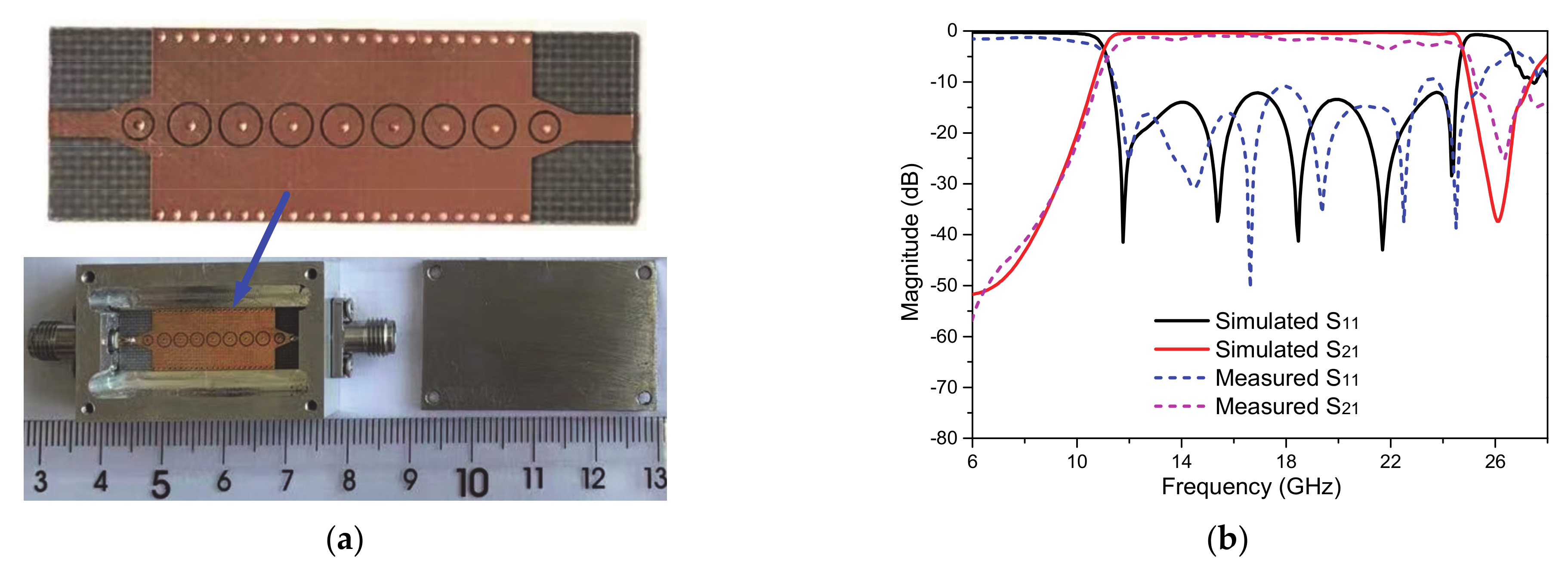
3. Design of Bandpass Filters Using the Proposed SSPPs
On the basis of the dispersion characteristics of the SSPPs, a BPF using the proposed SSPP waveguide is designed. Figure 3 shows the schematic configuration of the BPF, which is composed of three parts: microstrip line as the input/output port connected with the SMA connector (up to 27 GHz) for facilitating the measurement, a transition part, and a periodic SSPP array structure with seven-unit cells. Since the existence of microstrip line is in order to feed the SSPP structure, the width of w1 is set as 1.35 mm to realize the characteristic impedance of 50 Ω, for the impedance matching in RF circuit designs. Due to the momentum and impedance mismatchings between microstrip line and SSPPs, a simple transition part is necessary to be added by using a trapezoidal microstrip line and a smaller ring slot for the mode conversion. All detailed parameters are tabulated in Table 1.
Figure 3.
Schematic configuration of the BPF using the proposed SSPP.
Table 1.
Parameters of BPF Using the Proposed SSPP.
To further demonstrate the characteristics of the BPF using the proposed SSPP, a prototype example is fabricated as seen in Figure 4a with the identical dimensions in Table 1. Figure 4b shows the simulation and measurement results of the S-parameters, where the left and right edges of the passband are at 13 GHz and 24.6 GHz, respectively, basically consistent with the cutoff frequencies in Figure 2 for the parameters set in Table 1. Good agreement between the simulation and measurement can be observed. The center frequency is at 18.8 GHz and the relative bandwidth is 61.7%. It is speculated that using a dielectric substrate with lower loss tangent can improve the measured insertion losses.
Figure 4.
(a) Fabricated photograph of the BPF using SSPP and (b) the simulation and measurement of the BPF.
To validate the transmission characteristics of the proposed circuit, the electric field distributions at 20 GHz and 7 GHz are simulated by the commercial software CST Microwave Studio [] as shown in Figure 5a,b, which are located within the passband and at the out-of-band, respectively. The electromagnetic signals can efficiently propagate from microstrip line to the proposed SSPP waveguide at 20 GHz but are blocked quickly at the out-of-band, such as at 7 GHz.
Figure 5.
(a) Simulated electric field distributions of the BPF based on the proposed SSPP at 20 GHz. (b) Simulated electric field distributions at 7 GHz.
As mentioned above, the left and right edges of the BPF’s passband can be adjusted by the SIW and radius of the ring slot, respectively, thus the bandwidth and center frequency can be easily manipulated. Here, another SSPP unit cell example is designed with the lower cutoff frequency and asymptotic frequency at 11 GHz and 24.6 GHz, respectively. The parameters w3 = 9 mm and w = 9.8 mm are set different from those of the first filter example while the other dimensions are the same. Figure 6 illustrates the dispersion characteristic comparisons between the two examples, where the asymptotic frequencies are the same at 24.6 GHz since the cutoff frequency of the SSPP mode is not affected when the width of SIW wall is changed. For the lower cutoff frequency, it will be decreased from 13 GHz to 11 GHz, thus the bandwidth will be broadened accordingly. The dash line shown in Figure 6 is the dispersion curve of the light line for reference to the two examples.
Figure 6.
Dispersion characteristic comparisons between the SSPP unit cells with w3 = 7.4 mm and w = 8.2 mm, and w3 = 9 mm and w = 9.8 mm.
This BPF example based on the above-mentioned SSPP unit cell with the left and right edges of the passband at 11 GHz and 24.6 GHz is also fabricated and measured, as shown in Figure 7. In addition to the difference of the width of SIW wall, the only difference from the first filter example in Table 1 is the parameters of the trapezoidal microstrip line in the transition part: w2 = 3.15 mm, l2 = 2.25 mm.
Figure 7.
(a) Fabricated photograph of the second BPF example. (b) Its simulation and measurement results.
Figure 7a is the fabricated photograph and Figure 7b shows the comparisons between the simulation and measurement results, where they are in good agreement. It is observed that the left and right edges of the passband are at 11 GHz and 24.6 GHz, respectively, consistent with the cutoff frequencies in Figure 6. The center frequency of this BPF is at 17.8 GHz and the corresponding relative bandwidth is 76.4%, which is wider than that of the first filter example.
In addition, the electric field distributions of the BPF with wider bandwidth at in-band frequency 20 GHz and out-of-band frequency 7 GHz are also demonstrated in Figure 8, which validates the transmission and cutoff characteristics of the proposed SSPP. Obviously, the electric fields at 7 GHz suffer from strong suppression when propagating along the proposed structure. On the contrary, the electric fields at 20 GHz can transmit from the input to output ports smoothly.
Figure 8.
(a) Simulated electric field distributions of the second BPF example based on the proposed SSPP at 20 GHz. (b) Simulated electric field distributions at 7 GHz.
4. Conclusions
In this article, two BPFs based on the proposed SSPPs with good performance but different center frequencies and bandwidths have been presented. Combining with the SIW possessing high-pass property, the proposed SSPPs using ring slots and vias have been analyzed in detail and demonstrated experimentally. It is observed that the left and right edges of the BPF can be easily adjusted by changing the geometric parameters of the SSPPs, which will be of significant potential to the adaptive RF/terahertz front-end systems.
Author Contributions
Conceptualization, L.T. and K.X.; methodology, K.X.; software, L.T.; validation, L.T. and Y.L.; formal analysis, Y.L.; investigation, Y.G.; writing—original draft preparation, L.T. and K.X.; writing—review and editing, K.X.; supervision, K.X. and J.C. All authors have read and agreed to the published version of the manuscript.
Funding
This work was supported in part by the Scientific Research Projects of Fire Rescue Bureau of Emergency Management Department under Grant 2019XFGG11, in part by the Natural Science Foundation of Shaanxi Province under Grant 2021JQ-060, and in part by the “Siyuan Scholar” Fellowship of XJTU.
Institutional Review Board Statement
Not applicable.
Informed Consent Statement
Not applicable.
Data Availability Statement
The data presented in this study are available on request from the corresponding author.
Conflicts of Interest
The authors declare no conflict of interest.
References
- Barnes, W.L.; Dereux, A.; Ebbesen, T.W. Surface plasmon subwavelength optics. Nature 2003, 424, 824–830. [Google Scholar] [CrossRef]
- Pendry, J.B.; Martín-Moreno, L.; Garcia-Vidal, F.J. Mimicking surface plasmons with structured surfaces. Science 2004, 305, 847–848. [Google Scholar] [CrossRef]
- Xu, K.D.; Guo, Y.J.; Yang, Q.; Zhang, Y.L.; Deng, X.; Zhang, A.; Chen, Q. On-chip GaAs-based spoof surface plasmon polaritons at millimeter-wave regime. IEEE Photon. Technol. Lett. 2021, 33, 255–258. [Google Scholar] [CrossRef]
- Zhao, L.; Zhang, X.; Wang, J.; Yu, W.H.; Li, J.D.; Su, H.; Shen, X.P. A novel broadband band-pass filter based on spoof surface plasmon polaritons. Sci. Rep. 2016, 6, 36069. [Google Scholar] [CrossRef] [PubMed]
- Guo, Y.J.; Xu, K.D.; Liu, Y.H.; Tang, X.H. Novel surface plasmon polariton waveguides with enhanced field confinement for microwave-frequency ultra-wideband bandpass filters. IEEE Access 2018, 6, 10249–10256. [Google Scholar] [CrossRef]
- Xu, K.D.; Zhang, F.; Guo, Y.; Ye, L.; Liu, Y. Spoof surface plasmon polaritons based on balanced coplanar stripline waveguides. IEEE Photon. Technol. Lett. 2020, 32, 55–58. [Google Scholar] [CrossRef]
- Guo, Y.J.; Xu, K.D.; Deng, X.; Cheng, X.; Chen, Q. Millimeter-wave on-chip bandpass filter based on spoof surface plasmon polaritons. IEEE Electron Device Lett. 2020, 41, 1165–1168. [Google Scholar] [CrossRef]
- Qi, C.; Liao, S.; Xue, Q. Frequency splitter based on spoof surface plasmon polariton transmission lines. Appl. Phys. Lett. 2018, 113, 161902. [Google Scholar] [CrossRef]
- Kianinejad, A.; Chen, Z.N.; Qiu, C.W. A single-layered spoof-plasmon-mode leaky wave antenna with consistent gain. IEEE Trans. Antennas Propag. 2017, 65, 681–687. [Google Scholar] [CrossRef]
- Zhang, X.F.; Fan, J.; Chen, J.X. High gain and high-efficiency millimeter-wave antenna based on spoof surface plasmon polaritons. IEEE Trans. Antennas Propag. 2019, 67, 687–691. [Google Scholar] [CrossRef]
- Li, D.; Wang, J.A.; Liu, Y.; Chen, Z.; Yang, L. Compact quasi-elliptic bandpass filter with high selectivity using short-circuited coupled line. Microw. Opt. Technol. Lett. 2019, 61, 2873–2878. [Google Scholar] [CrossRef]
- Alnahwi, F.M.; Al-Yasir, Y.I.A.; Abdulhameed, A.A.; Abdullah, A.S.; Abd-Alhameed, R.A. A Low-Cost Microwave Filter with Improved Passband and Stopband Characteristics Using Stub Loaded Multiple Mode Resonator for 5 G Mid-Band Applications. Electronics 2021, 10, 450. [Google Scholar] [CrossRef]
- Li, D.; Xu, K.D. Multifunctional Switchable Filter Using Coupled-Line Structure. IEEE Microw. Wirel. Compon. Lett. 2021, 31, 457–460. [Google Scholar] [CrossRef]
- La, D.S.; Guan, X.; Chen, S.M.; Li, Y.Y.; Guo, J.W. Wideband Band-Pass Filter Design Using Coupled Line Cross-Shaped Resonator. Electronics 2020, 9, 2173. [Google Scholar] [CrossRef]
- Mrvić, M.; Potrebić, M.; Tošić, D. Compact E plane waveguide filter with multiple stopbands. Radio Sci. 2016, 51, 1895–1904. [Google Scholar] [CrossRef] [Green Version]
- Zhao, P.; Wu, K. Waveguide Filters with Central-Post Resonators. IEEE Microw. Wirel. Compon. Lett. 2020, 30, 657–660. [Google Scholar] [CrossRef]
- Tebeiro, F.; Arnedo, I.; Percaz, J.M.; Arrcgui, I.; Martin-Iglesias, P.; Lopetcgi, T.; Laso, M.A.G. Accurate Design Procedure for Waffle-Iron Low-Pass Filter. In Proceedings of the 2018 IEEE MTT-S International Microwave Symposium, Philadelphia, PA, USA, 10–15 June 2018. [Google Scholar]
- Hilt, A. Availability and Fade Margin Calculations for 5G Microwave and Millimeter-Wave Anyhaul Links. Appl. Sci. 2019, 9, 5240. [Google Scholar] [CrossRef] [Green Version]
- Xu, K.D.; Guo, Y.J.; Deng, X.J. Terahertz broadband spoof surface plasmon polaritons using high-order mode developed from ultra-compact split-ring grooves. Opt. Express 2019, 27, 4354–4363. [Google Scholar] [CrossRef]
- Li, J.; Shi, J.; Xu, K.D.; Guo, Y.J.; Zhang, A.; Chen, Q. Spoof surface plasmon polaritons developed from coplanar waveguides in microwave frequencies. IEEE Photon. Technol. Lett. 2020, 32, 1431–1434. [Google Scholar] [CrossRef]
- Wang, Y.; Hong, W.; Dong, Y.; Liu, B.; Tang, H.J.; Chen, J.; Yin, X.; Wu, K. Half mode substrate integrated waveguide (HMSIW) bandpass filter. IEEE Microw. Wirel. Compon. Lett. 2007, 17, 265–267. [Google Scholar] [CrossRef]
- Guan, D.; Peng, Y.; Zhang, Q.; Xiao, K.; Yong, S.-W. Hybrid Spoof Surface Plasmon Polariton and Substrate Integrated Waveguide Transmission Line and Its Application in Filter. IEEE Trans. Microw. Theory Tech. 2017, 65, 4925–4932. [Google Scholar] [CrossRef]
- Li, W.; Xu, K.D.; Tang, X.; Yang, Y.; Liu, Y.; Liu, Q. Substrate integrated waveguide cavity-backed slot array antenna using high-order radiation modes for dual-band applications in K-band. IEEE Trans. Antennas Propag. 2017, 65, 4556–4565. [Google Scholar] [CrossRef]
- CST Microwave Studio. CST Corp.: Darmstadt, Germany. Available online: www.cst.com (accessed on 1 August 2021).
Publisher’s Note: MDPI stays neutral with regard to jurisdictional claims in published maps and institutional affiliations. |
© 2021 by the authors. Licensee MDPI, Basel, Switzerland. This article is an open access article distributed under the terms and conditions of the Creative Commons Attribution (CC BY) license (https://creativecommons.org/licenses/by/4.0/).