Abstract
This paper presents two designs of high-efficiency polarizer reflectarray antennas able to generate a collimated beam in dual-circular polarization using a linearly polarized feed, with application to high-gain antennas for data transmission links from a Cubesat. First, an 18 cm × 18 cm polarizer reflectarray operating in the 17.2–22.7 GHz band has been designed, fabricated, and tested. The measurements of the prototype show an aperture efficiency of 52.7% for right-handed circular polarization (RHCP) and 57.3% for left-handed circular polarization (LHCP), both values higher than those previously reported in related works. Then, a dual-band polarizer reflectarray is presented for the first time, which operates in dual-CP in the frequency bands of 20 GHz and 30 GHz. The proposed antenna technology enables a reduction of the complexity and cost of the feed chain to operate in dual-CP, as a linear-to-circular polarizer is no longer required. This property, combined with the lightweight, flat profile and low fabrication cost of printed reflectarrays, makes the proposed antennas good candidates for Cubesat applications.
1. Introduction
CubeSats are a cost-efficient solution to conduct scientific research and to validate new communication technologies in space. The appearance of the CubeSat standard revolutionized the world of small satellites in the early 2000s, leading to the fast development of pico- and nano-satellite applications among universities, small technology companies, and other organizations [1,2]. CubeSats are typically built by several blocks of dimensions 10 cm × 10 cm × 10 cm and a maximum weight of 1.33 kg, called 1 U (unit volume for CubeSats). Due to the small size of the CubeSat, there is a limited volume in the spacecraft to accommodate the antenna systems required for remote sensing applications and data transmission links [3,4]. The establishment of a high-data-rate communication link between the Cubesat and the Earth (or another satellite) usually requires a high-gain antenna, which must be lightweight and present low stowage volume [4]. Some recent developments on high-gain antennas proposed for Cubesat applications are deployable mesh reflectors [5,6], folded-panel reflectarrays [7,8], metasurfaces [9,10], and membrane antennas [11].
Among the previous antenna types, reflectarrays are positioning as one of the most promising technologies for CubeSats [12]. Reflectarrays provide high values of gain and radiation efficiency (similar to those of reflectors), with the added advantage of their flat surface, which allows them to be easily folded and stowed on the spacecraft, as well as to implement simple deploying mechanisms in flight. NASA has recently launched two CubeSat missions using folded-panel reflectarrays as high-gain antennas: ISARA (Integrated Solar Array and Reflect-array Antenna) [7] and MarCO (Mars Cube One) [8]. Both reflectarrays operate in circular polarization (CP), which is more resistant to electromagnetic phenomena and polarization mismatch than linear polarization (LP). To design a CP reflectarray antenna, the conventional approach is based on the use of a CP feed [13,14,15], which normally includes a linear-to-circular polarizer in the feeding chain. The polarizer increases the cost and design complexity of the feeding chain and would require additional stowage volume in the CubeSat. For this reason, several reflectarray antennas have been proposed to produce a CP beam using an LP feed [16,17,18,19,20,21], performing LP-to-CP conversion at the same time as collimating a high-gain beam (hence, we will refer to them as polarizer reflectarrays). This technology allows to simplify the design of the feeding chain, also reducing its cost; however, the results reported to date show that it is difficult to achieve high aperture efficiency with a broad operating band [16,17,18,19,20,21].
In this paper, the authors present two designs of polarizer reflectarrays to produce a dual-CP beam using a dual-LP feed, with application to CubeSat missions in K/Ka-bands. First, a broadband polarizer reflectarray has been designed, manufactured, and tested, showing higher radiation efficiency than other polarizer reflectarrays reported in the literature. Then, the design of a dual-band polarizer reflectarray is presented for the first time, enabling simultaneous operation in dual-CP at the 20 GHz and 30 GHz bands. The results of both designs confirm the potential of reflectarrays as high-gain, low-stowage antennas for high-speed data transmission links from a Cubesat.
2. Operating Principle of the Polarizer Reflectarray
A reflectarray consists of a planar array of radiating elements which are illuminated by a feeder antenna (typically, a horn), in a similar way to a parabolic reflector [12]. To generate a collimated or a shaped beam, the reflectarray elements are designed to introduce a certain phase shift in the incident field from the feed-horn. The following expression can be used to obtain the phase shift (Φ) required in each reflectarray element to produce a focused beam in the direction (θb, φb):
where xi and yi are the Cartesian coordinates of the i-element with respect to the geometric center of the antenna surface, k0 is the propagation constant in vacuum, and Φ0 is a constant phase term applied to all the elements, which does not affect the generated beam (it can be used to control the absolute phase values of the elements).
Φ(xi, yi) = −k0 sin (θb) [xi cos (φb) + yi sin (φb)] + Φ0
In printed reflectarray antennas, the phase shift introduced by each reflectarray element is normally controlled by adjusting one or several of their geometrical parameters. Some reflectarray elements allow independent control of the phase shift in each linear component of the incident field, such as rectangular patches [16], crossed dipoles [17,18] and Jerusalem crosses [19]. Hence, each reflectarray element can be designed to introduce two different phase shifts, ΦX and ΦY, associated with the x and y linear components of the incident field (note that some single-layer reflectarray cells [22,23] have two planes of symmetry, which does not allow a different phase-shift in each field component). Although both phase shifts can be obtained by Equation (1) to produce a beam in the same direction, they can be calculated using a different phase constant for each LP (Φ0X and Φ0Y). If a dual-LP feed is used to illuminate the reflectarray, with the incident field oriented in the direction of the x and y axes of the reflectarray, the antenna will produce a collimated beam in dual-LP, see Figure 1a.
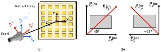
Figure 1.
(a) Reflectarray antenna and illuminating horn, showing the orientation of the dual-LP radiated by the feed in order to generate a dual-LP beam (Xf and Yf axes, in blue) or a dual-CP beam (X’f and Y’f axes, in red, obtained after rotating 45°). (b) Decomposition of the incident LP at ±45° slant into two orthogonal components in the direction of the x and y axes of the reflectarray. For simplicity, the reflectarray elements are represented as rectangular patches.
The design of a dual-CP reflectarray using a dual-LP feed can be accomplished by rotating the feed-horn so that the incident LP waves are oriented at 45° slant with respect to the x and y axes of the reflectarray, as shown in Figure 1a,b. Each incident LP is decomposed into two orthogonal components of similar amplitude (they will present the same amplitude in the case of normal incidence). The reflectarray elements are designed to provide the phase shifts required for a collimated beam while enforcing that ΦX = ΦY ± 90° by means of a proper election of the phase constants Φ0X and Φ0Y. This leads to a 90° phase difference between the x and y components of the reflected field, which will produce a reflected CP wave. As shown in Figure 1, the sense of the reflected CP (right-handed CP -RHCP- or left-handed CP -LHCP) is determined by the orientation of the incident LP (45° or −45°). Therefore, a reflectarray antenna with a dual-LP feed can generate a high-gain beam in dual-CP without the use of a polarizer in the feed chain.
3. Design and Demonstration of a Broadband Polarizer Reflectarray Antenna
A broadband polarizer reflectarray that produces a dual-CP beam with a linearly polarized feed has been designed, manufactured, and tested. The dimensions of the reflectarray surface are 180 mm × 180 mm (comprising 30 × 30 reflectarray cells), in order to obtain a maximum gain close to 30 dBi at 20 GHz and to be compatible with the size of a 3 U CubeSat, see Figure 2a. The reflectarray is designed to produce a focused beam in the direction θb = 25°, φb = 0°. The feed is placed at the coordinates (−85, 0, 180) mm according to the reference system of the reflectarray shown in Figure 1a. The offset configuration of the feed ensures that there will be no blockage of the radiated beam.
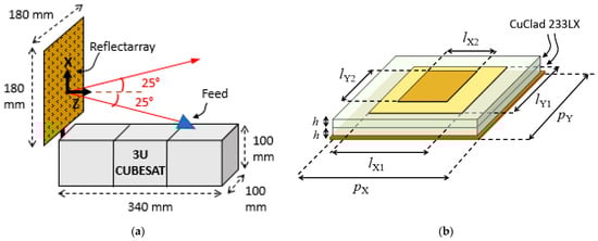
Figure 2.
(a) Representation of the reflectarray antenna mounted on the CubeSat. (b) Dual-layer reflectarray cell formed by two stacked rectangular patches. All units are in mm.
Dual-layer reflectarray cells formed by two stacked rectangular patches have been used for the design of the reflectarray antenna, as can be seen in Figure 2b. The use of two stacked patches instead of one patch provides a larger phase variation range for the reflection coefficient of the cell and results in a broadband performance of the reflectarray antenna [24]. The cell periodicity is pX = pY = 6 mm, which is smaller than half the wavelength at the operating frequencies of the reflectarray. The dimensions of the patches (lX1-lX2 and lY1-lY2) will be independently adjusted for each reflectarray cell, considering a range of variation from 1.6 mm to 5.5 mm. The two dielectric layers are implemented by commercial CuClad 233LX substrates, each with thickness h = 0.787 mm, a relative dielectric constant of 2.33, and a loss tangent of 0.0012. These substrates have been chosen because of their simplicity of manufacturing and low losses.
The phase shift distributions that must be introduced in each linear component of the incident field (x and y) to produce a dual-CP beam at 19.7 GHz (design frequency) are depicted in Figure 3. These phases have been obtained by applying Equation (1) with Φ0X = 250° and Φ0Y = 160°, so a 90° difference is achieved between the phase shifts associated with the x and y components, in order to generate a reflected CP wave from an incident LP with 45° skew, as explained in Section 2.
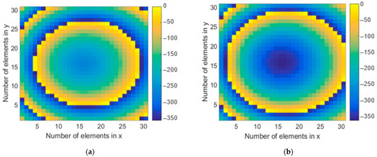
Figure 3.
Phase shifts (in degrees) that must be introduced by the reflectarray elements in the (a) x component and (b) y component of the incident field to produce a dual-CP beam at 19.7 GHz.
The oblique incidence in most of the reflectarray cells results in small differences between the amplitude of the x and y components in which the two LP radiated by the feed are decomposed, see Figure 4. These variations are not critical to perform the LP-to-CP conversion, since they are between −1 dB and 1 dB in most of the reflectarray cells.
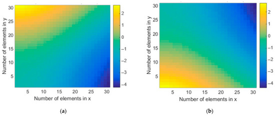
Figure 4.
Amplitude difference (in dB) between the x and y components for (a) the incident LP at 45° slant and (b) the incident LP at −45° slant.
The reflectarray cells made up of two stacked patches have been designed to introduce the phase shifts shown in Figure 3, accounting for the real incidence angles in each cell. The dimensions of the patches along the x and y axes (lX1-lX2 and lY1-lY2) are independently adjusted to introduce a different phase shift in each linear component of the incident field, keeping the following relations between the upper and lower patches: lX2 = 0.8 lX1, and lY2 = 0.8 lY1. This scale factor between the two layers provides two close resonances that lead to a smooth variation in the phase response of the cell in a range larger than 500°, as can be checked in Figure 5a,b, which show the amplitude and phase of the reflection coefficient associated to the x and y components of the incident field as a function of the corresponding patch dimensions. The results in Figure 5 have been obtained considering the following incidence angles: θinc = 25°, φinc = 0°, which correspond to the reflectarray cells located near to the geometrical center of the reflectarray antenna. The electromagnetic simulations have been performed using an in-house Method of Moments (MoM) code [25], which applies an infinite array model to obtain the reflection coefficients of the reflectarray cell. The MoM analysis tool has been satisfactorily validated in previous works by the manufacturing and measurement of several reflectarray prototypes in Ku [26] and Ka bands [27]. For the MoM simulations, the relative dielectric constant (2.33) and loss tangent (0.0012) of the CuClad layers are considered, so the simulations account for the dielectric losses of the substrates. The printed elements are modeled as perfect conductors since the conductivity losses of the copper are negligible at these frequencies.
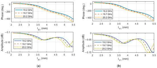
Figure 5.
Phase and amplitude of the reflection coefficient associated with the (a) x component and (b) y component of the incident field, at several frequencies in the 20 GHz band.
The dimensions of the rectangular patches have been adjusted cell-by-cell using the same electromagnetic software, which has been embedded in an iterative design routine. The photo-etching masks of the two reflectarray layers, with the final dimensions of the rectangular patches, are shown in Figure 6. The patches have been photo-etched on both sides of the upper CuClad 233 LX substrate. Then, this substrate with the printed elements has been bonded to the lower CuClad sheet (with copper in its bottom side) using 37-μm CuClad 6250 bonding film (relative dielectric constant of 2.32, and loss tangent of 0.0013). The reflectarray has been illuminated by a K-band pyramidal horn (Narda 638), which has a gain of 15.6 dBi at 20 GHz and provides around −9 dB illumination taper on the reflectarray edges. The horn has been properly positioned to radiate the incident LP first at 45° slant (so the reflectarray generates a focused beam in RHCP), and then, at −45° slant (to generate the beam in LHCP). A photograph of the fabricated reflectarray antenna demonstrator at the anechoic chamber of the Universidad Politécnica de Madrid is shown in Figure 7.
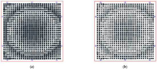
Figure 6.
Photo-etching masks of the designed reflectarray antenna, corresponding to the (a) lower layer and (b) upper layer of rectangular patches.
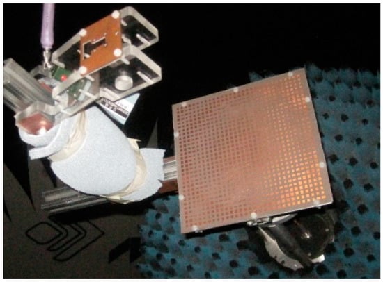
Figure 7.
Picture of the fabricated reflectarray antenna at the anechoic chamber.
The comparison of the simulated and measured radiation patterns of the polarizer reflectarray antenna at 19.7 GHz in the xz-plane (the plane that contains the feed and the beam) and in the azimuth plane (the orthogonal plane tilted 25° with respect to the z-axis) for the beams generated in RHCP and LHCP is shown in Figure 8. Concerning the simulations, the field radiated by the horn has been modeled using a typical cosq (θ) distribution with q = 10.5. The reflected field components on the reflectarray surface have been calculated by the abovementioned MoM software, and then, these components have been used to obtain the numerical radiation patterns of the antenna. As can be seen in Figure 8, there is a good match between measurements and simulated results. There is a small deviation of the beam in azimuth (around 0.8°) which is mainly attributed to misalignments of the measurement setup and fabrication tolerances in the pieces of the horn supporting structure.
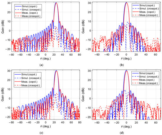
Figure 8.
Comparison of simulated and measured radiation patterns at 19.7 GHz for the beam produced in RHCP (a) in the xz-plane and (b) in the azimuth plane, and for the beam produced in LHCP (c) in the xz-plane and (d) in the azimuth plane.
The measured radiation patterns of the polarizer reflectarray antenna at 19.7 GHz show a maximum gain of 29.95 dBi in LHCP and 29.58 dBi in RHCP, while the side-lobe levels (SLL) are lower than −19.5 dB in both polarizations. The aperture efficiency at 19.7 GHz is 56.3% for LHCP and 51.7% for RHCP. Moreover, the measured cross-polar levels are 26 dB below the co-polar maximum, which leads to an axial ratio (AR) of 0.87 dB.
The measured radiation patterns of the polarizer reflectarray at other frequencies, ranging from 18.2 GHz to 21.2 GHz, are shown in Figure 9 for the beam produced in LHCP. As can be seen, the antenna exhibits a stable gain and SLL. The cross-polar levels remain fairly stable at frequencies lower than 20 GHz, while they increase above 20 GHz. A similar in-band performance is achieved for the RHCP beam. Figure 10 shows the maximum gain of the reflectarray antenna as a function of frequency, comparing the measured and simulated gain values for both RHCP and LHCP in the frequency range from 17.2 GHz to 22.7 GHz. The maximum gain in the operating band is 30.2 dBi for LHCP and 29.84 dBi for RHCP (both achieved at 20.1 GHz) which correspond to aperture efficiencies of 57.3% for LHCP and 52.7% for RHCP, both values higher than those previously reported in other polarizer reflectarrays [16,17,18,19,20,21]. The 1-dB gain bandwidth is around 4.1 GHz (relative bandwidth of 20%) and the 3-dB gain bandwidth is larger than 5.5 GHz (relative bandwidth of 27.5%). The maximum SLL over the entire bandwidth is −16 dB. The AR performance of the polarizer reflectarray has also been studied in the 17.2–22 GHz band (see Figure 11), showing a 3-dB AR relative bandwidth of 19% (between 17.2 GHz and 20.7 GHz) for both RHCP and LHCP.
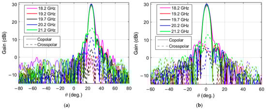
Figure 9.
Measured radiation patterns at several frequencies (from 18.2 to 21.2 GHz) for the beam produced in LHCP: (a) in the xz-plane and (b) in the azimuth plane.
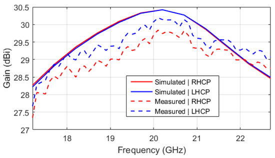
Figure 10.
Measured and simulated gain of the reflectarray antenna as a function of frequency.
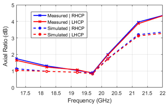
Figure 11.
Measured and simulated axial ratio as a function of frequency.
Table 1 presents a comparison of the main antenna parameters between the polarizer reflectarray demonstrator shown in this work and other polarizer reflectarrays reported in the literature. As can be seen, the proposed reflectarray exhibits the highest aperture efficiency. The 1-dB gain bandwidth is comparable to that reported in [17] and the SLL is lower than previous works (note that the SLL in [18] is provided only at the center frequency). Moreover, the proposed reflectarray has been designed with an offset-feed configuration to avoid aperture blockage produced by the feed, and it is the only polarizer reflectarray with a tilted beam (25°). The antenna can be designed for larger fixed scanned beams, up to 60° from broadside, at the cost of the corresponding reduction in directivity (which in this case is around 0.5 dB). Despite the scanned beam, the aperture efficiency of the proposed antenna is higher than that of the other polarizer reflectarrays in the literature (with broadside beams).

Table 1.
Comparison of this work with previously reported polarizer reflectarrays.
4. Design of a Dual-Band Polarizer Reflectarray Antenna
In all previous works about polarizer reflectarrays, the antenna operates over a single frequency band to produce a high-gain beam in dual-CP. In this Section, a dual-band polarizer reflectarray is presented for the first time, which is designed to operate in the frequency bands of 19.2–20.2 GHz and 29–30 GHz. Again, the reflectarray surface is formed by a rectangular array of 30 × 30 cells, but in this case, the cell dimensions have slightly been reduced to 5.7 mm × 5.7 mm, to prevent the appearance of grating lobes at the higher operating frequencies. Thus, the dimensions of the reflectarray surface are 171 mm × 171 mm. An offset-feed configuration, like the one shown in Figure 2a, has been considered, with the feed placed at the coordinates (−40, 0, 195) mm. The antenna is designed to produce a focused beam in dual-CP in the direction θb = 13°, φb = 0°.
The required phase shift distributions at 19.7 GHz and 29.5 GHz (design frequencies) that must be introduced in the x and y components of the incident field to produce a focused beam at θb = 13°, φb = 0° are shown in Figure 12. These phases have been obtained by applying Equation (1) with the following relation between the phase constants: Φ0X = Φ0Y + 90°, so that an incident LP wave at 45° slant will be converted into a reflected RHCP wave at both bands, while an incident LP at −45° slant will be transformed into LHCP. Note that this design method allows changing the sense of the CP between the two frequency bands, considering Φ0X = Φ0Y + 90° when computing the phases at 19.7 GHz, and Φ0X = Φ0Y − 90° when doing the same at 29.5 GHz.
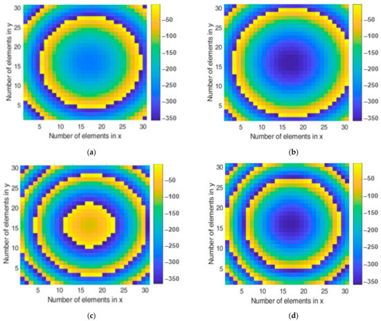
Figure 12.
Phase shifts (in degrees) that must be introduced by the elements of the dual-band polarizer reflectarray in each component of the incident field: (a) x component at 19.7 GHz, (b) y component at 19.7 GHz, (c) x component at 29.5 GHz, and (d) y component at 29.5 GHz.
To implement the four-phase distributions shown in Figure 12, the reflectarray elements must be able to provide a different phase shift in each linear component (x and y) at each frequency (19.7 GHz and 29.5 GHz). Dual-layer reflectarray cells have been used, where the rectangular patches have been replaced by orthogonally arranged groups of stacked parallel dipoles, as depicted in Figure 13. The dipoles printed on the lower dielectric layer (lengths lX1-lX2-lX3, and lY1-lY2-lY3) are used to adjust the phase shift introduced at 19.7 GHz, while the upper dipoles (lengths lX4-lX5 and lY4-lY5) control the phases introduced at 29.5 GHz. Besides, the use of orthogonal groups of dipoles (lengths lXi and lYi) enables independent phasing in each linear component of the incident field at both operating bands. A detailed explanation about the performance of this structure can be found in [27,28], where scaled versions of the cell were used for the design of dual-LP reflectarrays in the Ku/Ka-bands. In this work, the same cell structure is applied to design a dual-band, dual-CP reflectarray antenna.
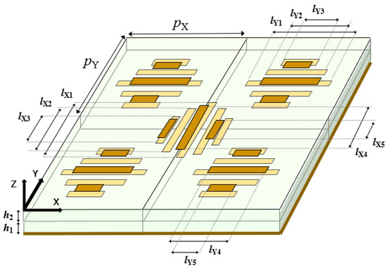
Figure 13.
Dual-layer reflectarray cells are formed by orthogonally arranged groups of dipoles, each comprising five dipoles on the bottom dielectric layer and three dipoles on the upper layer.
The two dielectric layers of the reflectarray are implemented using polycarbonate (permittivity of 2.8 and loss tangent of 0.0005) with a different thickness for each layer: h1 = 1.3 mm and h2 = 0.6 mm. This material can be used to fabricate the reflectarray by additive manufacturing processes using a 3D printer [29], resulting in a low-cost antenna for Cubesats. The cell periodicity is pX = pY = 5.7 mm, which corresponds to 0.57·λ at 30 GHz. The width of the dipoles is 0.25 mm, and the distance between parallel dipoles (from edge to edge) is 0.25 mm in the lower layer and 0.5 mm in the upper layer. To achieve a smooth phase response at the two operation bands of the antenna, the following relations are set between the lengths of the dipoles: lX2(Y2) = 0.81·lX1(Y1), lX3(Y3) = 0.62·lX1(Y1), lX5(Y5) = 0.81·lX4(Y4). The phase and amplitude responses of the reflectarray cell associated to the x component of the incident field are shown in Figure 14a,b for the 20 GHz and 30 GHz bands, respectively. These results have been obtained by combining MoM analysis with the local periodicity assumption and considering that the incidence angles on the reflectarray cell are θinc = 10°, φinc = 0°, which correspond to the central part of the reflectarray surface. A phase range larger than 400° is obtained in both frequency bands, with low dielectric losses (similar performance is achieved for the y component).
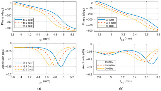
Figure 14.
Phase and amplitude of the reflection coefficient associated with the x component of the incident field (a) at the lower band (19.2–20.2 GHz) and (b) at the upper band (29–30 GHz).
The lengths of the dipoles in each reflectarray layer have been optimized to achieve the required phase-shift values for each frequency and polarization, using an iterative design routine similar to the one used in Section 3. The photo-etching masks of the two reflectarray layers, with the final dimensions of the dipoles after the design process, are presented in Figure 15.
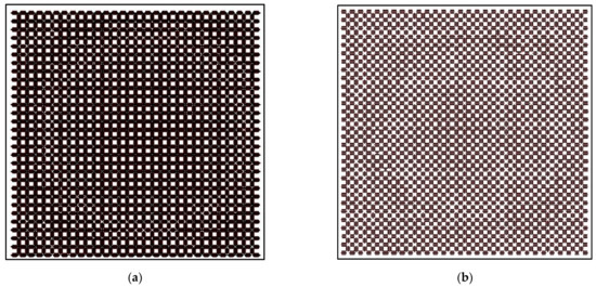
Figure 15.
Photo-etching masks for the (a) lower layer and (b) upper layer of dipoles.
Figure 16 shows the simulated radiation patterns in RHCP and LHCP of the designed dual-band polarizer reflectarray at 19.7 GHz and 29.5 GHz (center frequencies). To obtain these results, the electromagnetic field radiated by the feed has been modeled by a cosq (θ) distribution with q = 10.5 at the 20 GHz band and q = 10.7 at the 30 GHz band. Note that the feed has been properly oriented to produce two LP skewed at 45° and −45° with respect to the x and y axes of the reflectarray, as it was done in Section 3 with the single-band polarizer reflectarray. The maximum gain provided by the reflectarray is 30 dBi at 19.7 GHz and 32 dBi at 29.5 GHz (same gain in RHCP and LHCP). These values are associated with aperture efficiencies of 63% at 19.7 GHz and 44.7% at 29.5 GHz. The SLL is below −19 dB at both frequencies. The cross-polar levels at 19.7 GHz are 19 dB below the co-polar maximum, while at 29.5 GHz the cross-polar levels are 15 dB and 13 dB below the co-polar maximum for RHCP and LHCP, respectively.
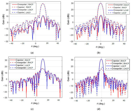
Figure 16.
Simulated radiation patterns: at 19.7 GHz (a) in the xz-plane and (b) in the azimuth plane, and 29.5 GHz (c) in the xz-plane, and (d) in the azimuth plane.
The main limitation of the designed polarizer reflectarray is the cross-polar levels at the higher frequency, which will reduce the available bandwidth. The AR at 29.5 GHz is around 3.1 dB in RHCP and 3.9 dB in LHCP, while at 19.7 GHz the AR is 1.9 dB. The high cross-polar levels are mainly produced by phase errors introduced by the reflectarray elements since some of them are not able to simultaneously provide the exact phases required in each polarization and frequency without errors. Advanced optimizations would be required to reduce the phase errors during the design of the reflectarray elements and improve the AR at higher frequencies.
The antenna performance has also been evaluated within the two operating bands. Concerning the 19.2–20.2 GHz band, the gain variation is within ±0.5 dB, and the cross-polar levels are between 18 dB and 20 dB below the co-polar maximum (AR between 1.75 and 2.2 dB). This stable performance allows the reflectarray to operate in wider bandwidths, e.g., from 18.95 GHz to 20.45 GHz (a total bandwidth of 1.5 GHz) with minor variations in gain and AR. On the other hand, the available bandwidth centered at 29.5 GHz has been reduced to 0.6 GHz (29.2–29.8 GHz) to ensure that the cross-polar levels are at least 12.5 dB below the co-polar. The gain variation in this band is within ±0.3 dB. These results confirm the dual-band operation of the polarizer reflectarray.
5. Conclusions
Two designs of high-efficiency polarizer reflectarray antennas to operate in dual-CP using a dual-LP feed have been presented in this paper, with application to high-gain antennas for Cubesats. First, a broadband polarizer reflectarray operating in the 17.2–22.7 GHz band has been designed, fabricated, and tested, showing an aperture efficiency of 52.7% for RHCP and 57.3% for LHCP, both values higher than those reported in previous works on polarizer reflectarrays. Then, a dual-band polarizer reflectarray has been proposed for the first time, which operates in the frequency bands of 19.2–20.2 GHz and 29.2–29.8 GHz. The results of both designs are promising and confirm the potential of polarizer reflectarrays to be used as high-gain, low-cost antennas for Cubesats, reducing the complexity and cost of the antenna system by no longer requiring a linear-to-circular polarizer in the feeding chain.
Author Contributions
Conceptualization, J.A.E.; Formal analysis, E.M.-d.-R.; Funding acquisition, J.A.E.; Investigation, E.M.-d.-R., D.M.-d.-R., R.L.-S. and I.L.; Methodology, E.M.-d.-R., R.L.-S. and J.A.E.; Project administration, J.A.E.; Software, E.M.-d.-R., D.M.-d.-R., R.L.-S. and I.L.; Supervision, J.A.E.; Validation, R.L.-S. and J.A.E.; Writing—Original draft, E.M.-d.-R. and D.M.-d.-R.; Writing—Review & editing, E.M.-d.-R. and J.A.E. All authors have read and agreed to the published version of the manuscript.
Funding
This research was funded by the European Regional Development Fund (ERDF) and the Spanish Ministry of Economy and Competitiveness, under Project TEC2016-75103-C2-1-R, and by the European Space Agency ESTEC, under Contract 4000117113/16/NL/AF.
Conflicts of Interest
The authors declare no conflict of interest.
References
- Puig-Suari, J.; Turner, C.; Ahlgren, W. Development of the standard CubeSat deployer and a CubeSat class PicoSatellite. In Proceedings of the 2001 IEEE Aerospace Conference, Big Sky, MT, USA, 10–17 March 2001; pp. 1/347–1/353. [Google Scholar]
- Waydo, S.; Henry, D.; Campbell, M. CubeSat design for LEO-based Earth science missions. In Proceedings of the 2001 IEEE Aerospace Conference, Big Sky, MT, USA, 9–16 March 2002. [Google Scholar]
- Abulgasem, S.; Tubbal, F.; Raad, R.; Theoharis, P.I.; Lu, S.; Iranmanesh, S. Antenna designs for CubeSats: A review. IEEE Access 2021, 9, 45289–45324. [Google Scholar] [CrossRef]
- Chahat, N.; Decrossas, E.; Gonzalez-Ovejero, D.; Yurduseven, O.; Radway, M.J.; Hodges, R.E.; Estabrook, P.; Baker, J.D.; Bell, D.J.; Cwik, T.A.; et al. Advanced CubeSat antennas for Deep Space and Earth Science missions: A review. IEEE Antennas Propag. Mag. 2019, 61, 37–46. [Google Scholar] [CrossRef] [Green Version]
- Chahat, N.; Hodges, R.E.; Sauder, J.; Thomson, M.; Peral, E.; Rahmat-Samii, Y. CubeSat deployable Ka-band mesh reflector antenna development for earth science missions. IEEE Trans. Antennas Propag. 2016, 64, 2083–2093. [Google Scholar] [CrossRef]
- Rahmat-Samii, Y.; Manohar, V.; Kovitz, J.M.; Hodges, R.E.; Freebury, G.; Peral, E. Development of highly constrained 1 m Ka-band mesh deployable offset reflector antenna for next generation CubeSat radars. IEEE Trans. Antennas Propag. 2019, 67, 6254–6266. [Google Scholar] [CrossRef]
- Hodges, R.E.; Radway, M.J.; Toorian, A.; Hoppe, D.J.; Shah, B.; Kalman, A.E. ISARA—Integrated Solar Array and Reflectarray CubeSat deployable Ka-band antenna. In Proceedings of the IEEE International Symposium on Antennas and Propagation & USNC/URSI National Radio Science Meeting, Vancouver, BC, Canada, 19–24 July 2015; pp. 2141–2142. [Google Scholar]
- Hodges, R.E.; Chahat, N.; Hoppe, D.J.; Vacchione, J.D. A deployable high-gain antenna bound for Mars: Developing a new folded-panel reflectarray for the first CubeSat mission to Mars. IEEE Antennas Propag. Mag. 2017, 59, 39–49. [Google Scholar] [CrossRef]
- González-Ovejero, D.; Chahat, N.; Sauleau, R.; Chattopadhyay, G.; Maci, S.; Ettorre, M. Additive manufactured metal-only modulated metasurface antennas. IEEE Trans. Antennas Propag. 2018, 66, 6106–6114. [Google Scholar] [CrossRef]
- Yurduseven, O.; Lee, C.; González-Ovejero, D.; Ettorre, M.; Sauleau, R.; Chattopadhyay, G.; Fusco, V.; Chahat, N. Multi-beam Si/GaAs holographic metasurface antenna at W-band. IEEE Trans. Antennas Propag. 2021, 69, 3523–3528. [Google Scholar] [CrossRef]
- Warren, P.A.; Steinbeck, J.W.; Minelli, R.J.; Mueller, C. Large, deployable S-band antenna for a 6U CubeSat. In Proceedings of the 29th Annual American Institution Aeronautics and Astronautics/Utah State University Conference Small Satellites, Andover, MA, USA, 31 July 2015; pp. 1–7. [Google Scholar]
- Huang, J.; Encinar, J.A. Reflectarray Antennas; IEEE Press: Piscataway, NJ, USA, 2008. [Google Scholar]
- Strassner, B.; Han, C.; Chang, K. Circularly polarized reflectarray with microstrip ring elements having variable rotation angles. IEEE Trans. Antennas Propag. 2004, 52, 1122–1125. [Google Scholar] [CrossRef]
- Yu, A.; Yang, F.; Elsherbeni, A.Z.; Huang, J.; Kim, Y. An offset-fed X-band reflectarray antenna using a modified element rotation technique. IEEE Trans. Antennas Propag. 2012, 60, 1619–1624. [Google Scholar] [CrossRef]
- Gao, Q.; Wang, J.; Li, Y.; Li, Z. A multiresonant element for bandwidth enhancement of circularly polarized reflectarray antennas. IEEE Antennas Wirel. Propag. Lett. 2018, 17, 727–730. [Google Scholar] [CrossRef]
- Zhao, G.; Jiao, Y.-C.; Zhang, F.; Zhang, F.S. A subwavelength element for broadband circularly polarized reflectarrays. IEEE Antennas Wireless Propag. Lett. 2010, 9, 330–333. [Google Scholar] [CrossRef]
- Ren, L.-S.; Jiao, Y.-C.; Li, F.; Zhao, J.J.; Zhao, G. A dual-layer T-shaped element for broadband circularly polarized reflectarray with linearly polarized feed. IEEE Antennas Wireless Propag. Lett. 2011, 10, 407–410. [Google Scholar]
- Chen, Y.-Y.; Ge, Y.; Bird, T.S. An offset reflectarray antenna for multipolarization applications. IEEE Antennas Wireless Propag. Lett. 2016, 15, 1353–1356. [Google Scholar] [CrossRef]
- Wu, G.-B.; Qu, S.-W.; Yang, S.; Chan, C.H. Broadband, single-layer dual circularly polarized reflectarrays with linearly polarized feed. IEEE Trans. Antennas Propag. 2016, 64, 4235–4241. [Google Scholar] [CrossRef]
- Abadi, S.M.A.M.H.; Behdad, N. Broadband true-time-delay circularly polarized reflectarray with linearly polarized feed. IEEE Trans. Antennas Propag. 2016, 64, 4891–4896. [Google Scholar] [CrossRef]
- Lee, S.R.; Lim, E.H.; Lo, F.L.; Ng, W.H. Circularly polarized elliptical microstrip patch reflectarray. IEEE Trans. Antennas Propag. 2017, 65, 4322–4327. [Google Scholar] [CrossRef]
- Chaharmir, M.R.; Shaker, J.; Legay, H. Broadband Design of a Single Layer Large Reflectarray Using Multi Cross Loop Elements. IEEE Trans Antennas Propag. 2009, 57, 3363–3366. [Google Scholar] [CrossRef]
- Hasani, H.; Peixeiro, C.; Skrivervik, A.; Perruisseau-Carrier, J. Single-layer quad-band printed reflectarray antenna with dual linear polarization. IEEE Trans. Antennas Propag. 2015, 63, 5522–5528. [Google Scholar] [CrossRef]
- Encinar, J.A. Design of two-layer printed reflectarrays using patches of variable size. IEEE Trans. Antennas Propag. 2001, 49, 1403–1410. [Google Scholar] [CrossRef]
- Wan, C.; Encinar, J.A. Efficient computation of generalized scattering matrix for analyzing multilayered periodic structures. IEEE Trans. Antennas Propag. 1995, 43, 1233–1242. [Google Scholar]
- Encinar, J.A.; Arrebola, M.; de la Fuente, L.F.; Toso, G. A transmit-receive reflectarray antenna for direct broadcast satellite applications. IEEE Trans. Antennas Propag. 2011, 59, 3255–3264. [Google Scholar] [CrossRef]
- Martinez-de-Rioja, E.; Encinar, J.A.; Barba, M.; Florencio, R.; Boix, R.R.; Losada, V. Dual polarized reflectarray transmit antenna for operation in Ku- and Ka-bands with independent feeds. IEEE Trans. Antennas Propag. 2017, 65, 3241–3246. [Google Scholar] [CrossRef] [Green Version]
- Martinez-de-Rioja, E.; Encinar, J.A.; Florencio, R.; Boix, R.R. Reflectarray in K and Ka bands with independent beams in each polarization. In Proceedings of the 2016 IEEE International Symposium on Antennas and Propagation (APSURSI), Fajardo, PR, USA, 26 June–1 July 2016; pp. 1150–1199. [Google Scholar]
- Castro, J.; Rojas-Nastrucci, E.A.; Ross, A.; Weller, T.M.; Wang, J. Fabrication, modelling, and application of ceramic-thermoplastic composites for fused deposition modeling of microwave components. IEEE Trans. Microw. Theory Tech. 2017, 65, 2073–2084. [Google Scholar] [CrossRef]
Publisher’s Note: MDPI stays neutral with regard to jurisdictional claims in published maps and institutional affiliations. |
© 2021 by the authors. Licensee MDPI, Basel, Switzerland. This article is an open access article distributed under the terms and conditions of the Creative Commons Attribution (CC BY) license (https://creativecommons.org/licenses/by/4.0/).