Article

Orbital Angular Momentum-Based Multiple-Input-Multiple- Output with Receive Antenna Shift Keying for 6G

Department of IT Convergence Engineering, Kumoh National Institute of Technology, Gyeongbuk 39177, Korea
*
Author to whom correspondence should be addressed.
Electronics 2021, 10(13), 1567; https://doi.org/10.3390/electronics10131567
Submission received: 11 May 2021 / Revised: 23 June 2021 / Accepted: 25 June 2021 / Published: 29 June 2021
(This article belongs to the Special Issue Toward a New Era of Radio Access Technologies for 5G and Beyond)

Abstract

:
Spectral efficiency is a major concern for future 6G wireless communication systems. Thus, an appropriate scheme is needed to provide channel capacity improvement for multiple transmitters and receiver-based wireless communication systems without consuming extra resource for communication (e.g., frequency/time/code) or causing interference. Therefore, to fulfill the mentioned requirements for the future 6G wireless network, orbital angular momentum-based multiple-input-multiple-output (OAM-MIMO) multiplexing technique is incorporated with the receive antenna shift keying (RASK) technique in this study (termed as the OAM-MIMO-RASK scheme). OAM-MIMO-RASK can transfer multiple symbols from multiple transmitters to different receivers simultaneously by using multiple subchannels using the OAM and RASK techniques without any interference or additional resource (frequency/time/code). The numerical results illustrated that the proposed OAM-MIMO-RASK can achieve almost double capacity than the existing OAM-MIMO scheme and significantly higher capacity than the existing RASK-based scheme for different values of signal-to-noise ratio. Moreover, the simulation result is validated by the theoretical result which is also shown by the numerical result. In addition, due to different normalized distances from the transmitters and receivers, the proposed OAM-MIMO-RASK scheme can achieve almost double capacity than the existing OAM-MIMO scheme by using OAM-MIMO and RASK technique effectively which is also depicted by the numerical results.

1. Introduction

The prompt evolution of wireless communication systems necessitates advanced communication technology that can provide high spectral efficiency and massive connectivity for mobile wireless communication [1]. The use of small cells and millimeter-wave (mmWave) bands is vital factor for future 6G wireless networks [2]. The radio frequency-based orbital angular momentum (OAM) mode has received significant attention from the academic and industrial areas with the objective of enhancing the spectral efficiency (SE) of mmWave-based 6G wireless communication systems [3,4,5]. Traditional resources (e.g., time and frequency) of plane-wave-based wireless communication are well used. Thus, to increase the SE of future 6G wireless communication, a state-of-the-art degree of freedom need to be used. Previous studies showed that OAM uses a new degree of freedom. OAM mode is treated as a state-of-the-art degree of freedom for information transmission [6,7]. The OAM uses phase differences related to the azimuth angle of the propagating electromagnetic wave. By using multiple OAM modes for information transmission, the SE of the wireless communication is expected to significantly increase.
Several OAM multiplexing techniques were discussed in [8]. Although there are several issues that should be solved regarding the previous OAM multiplexing techniques. First, due to the location of the receiving antenna, the signal-to-noise ratio (SNR) is degraded significantly. Secondly, the number of usable OAM modes is limited owing to the mode-dependent beam divergence issue. Because the higher OAM modes cause large attenuation issues at the receiving end due to the beam divergence issue [9].
To overcome the first issue, the elevated degree of freedom for transmitting (Tx) and receiving (Rx) antennas can be used using various uniform circular arrays (UCAs). Owing to this, signal reception at the null region can be avoided and antenna selection along with receiver diversity can be achieved as well [9]. To mitigate the second problem, line-of-sight (LOS) OAM-MIMO can simultaneously transmit a significant number of the data streams with a minimum number of OAM modes and avoiding the higher-order OAM modes [9].
Moreover, considering that the mode combination technique with the OAM-MIMO multiplexing can overcome the inter-channel interference (ICI) and inter-modal interference (IMI) by exploiting uncorrelated subchannels. Thus, multiple data streams can be simultaneously transmitted without any interference issue to the Rx UCAs. Hence, the channel capacity is enhanced significantly without any extra resource for communication (e.g., frequency/time/code) or interference issue [10]. However, the previous studies were not considered multiple Tx and Rx-based OAM-MIMO wireless communication for 6G. Multiple Tx and Rx-based downlink (DL) OAM-MIMO wireless communication required a suitable transmission technique that can improve the channel capacities of Rxs and sum capacity (SC). Therefore, a suitable technique is required to improve the DL OAM-MIMO multiple Tx and multiple Rx-based 6G wireless communication systems excluding any excess resource.
Receive antenna shift keying (RASK) uses the spatial modulation (SM) principle which is suitable for multiple Tx and Rx-based wireless communication systems. The RASK receives an antenna-based SM following the antenna index mapping technique [11]. Therefore, DL OAM-MIMO is integrated with the RASK technique in this study (Termed as OAM-MIMO-RASK). By using the proposed OAM-MIMO-RASK scheme, multiple UCAs of different Tx can be simultaneously transmitted to the respective Rx UCAs [12]. Hence, by using the RASK technique, the channel capacity of multiple Tx- and Rx-based OAM-MIMO can be considerably improved without any interference or additional resource. Therefore, according to previous works on mmWave-based future wireless communication, channel capacity is a vital metric representing the SE of the communication system [2]. Moreover, the misalignment issue is a crucial issue in OAM-based wireless communication systems. The proposed DL OAM-MIMO-RASK scheme is considered along with non-coaxial Tx and Rx UCAs to prevail the misalignment problem of the Tx and Rx UCAs [13]. In addition, our proposed OAM-MIMO-RASK scheme can enhance the channel capacities of the Rxs and sum capacity (SC) of the receivers significantly by using the OAM-MIMO technique effectively and transferring additional information using the RASK technique compared to conventional OAM-MIMO and RASK-based schemes.

1.1. Related Works

Owing to the rapid development of IoT and enabling technologies for 6G wireless communications, the main resources are already used as the main multiple access modes. Moreover, dividing these resources caused the degradation of channel capacities because the resources were not simultaneously used, and they were divided among the users. Hence, a new wireless transmission strategy is required to meet the capacity requirements of future 6G wireless communication systems [14].
Moreover, owing to the emerging application of mobile internet services, the requirements of transmission capacity for future 6G wireless communication have significantly increased. Therefore, higher capacity requirements and SE of a wireless network are required. Traditional spectrum exploitation reaches the saturation level. Moreover, the SE approaches the Shannon limit. Hence, the development of new transmission capacities is required. Thus, high-band technology has been adopted for mmWave communications [15]. Different concepts and strategies have been proposed in recent studies to improve the capacity of wireless transmissions, such as beamforming designs, resource allocation schemes, and multiple antenna-based schemes [16,17,18].
Compared to other techniques, the OAM mode can provide a new degree of freedom for mmWave-based wireless communication system [19]. Moreover, OAM mode-based multiplexing reduces the attenuation of the OAM beam, increases the coverage distance of the link, and reduces the size of Tx and Rx in the case of mmWave wireless communication system [20]. Experimental results have shown comparisons between OAM and MIMO systems [21,22,23]. However, OAM has limitations for channel multiplexing [24]. Thus, the capacity of OAM-based wireless communication systems cannot achieve greater capacity than MIMO wireless communication systems [24]. Moreover, the OAM SM mmWave wireless communication system can provide a larger capacity than the MIMO mmWave wireless communication system [25]. In contrast, there is a practical limitation to the use of higher-order OAM modes owing to the divergence issue of the higher-order OAM beam [10].
OAM-MIMO multiplexing has been introduced to improve the design of the antenna configuration into multiple UCAs [26]. Moreover, multiple data streams can be generated and transmitted in a parallel manner by using the same OAM mode using the OAM-MIMO technique. Thus, channel capacities significantly improve compared to conventional OAM communication system without using the higher-order OAM modes [26].
All the above-mentioned works were not suitable for multiple Tx and Rx-based 6G wireless communication systems. In contrast, RASK is a suitable technique for handling multiple transmitters and receiver-based wireless communication systems [11]. However, conventional RASK cannot provide parallel transmission to different receivers and provide enormous channel capacities to the Rxs.
Therefore, multiple Tx and Rx UCA-based OAM-MIMO techniques were integrated with RASK in this study. Thus, multiple parallel transmission is possible by the proposed technique for multiple receivers without any extra resource and without any IMI or ICI issue as well. As a result, the proposed scheme provides remarkably enhanced channel capacities compared to the conventional schemes for different Rxs as well as SC of the receivers.

1.2. Contributions and Organization

The major contributions of this study are concisely described as below:
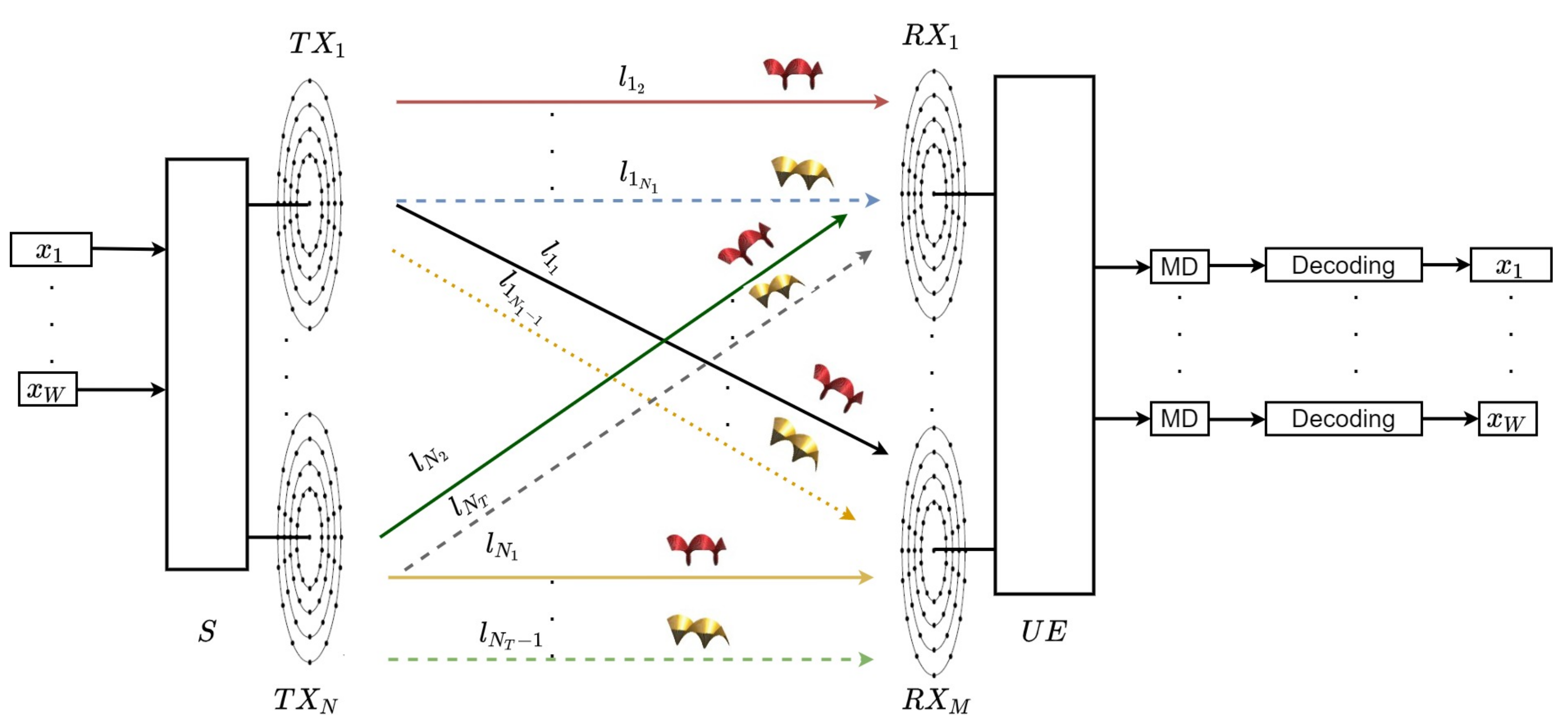
  • DL OAM-MIMO is integrated with the RASK technique herein for the future 6G wireless communication system (termed as the OAM-MIMO-RASK scheme).
  • The proposed scheme is assumed with non-coaxial Tx and Rx UCAs to solve the misalignment issues of the transmitter and receiver of the proposed scheme.
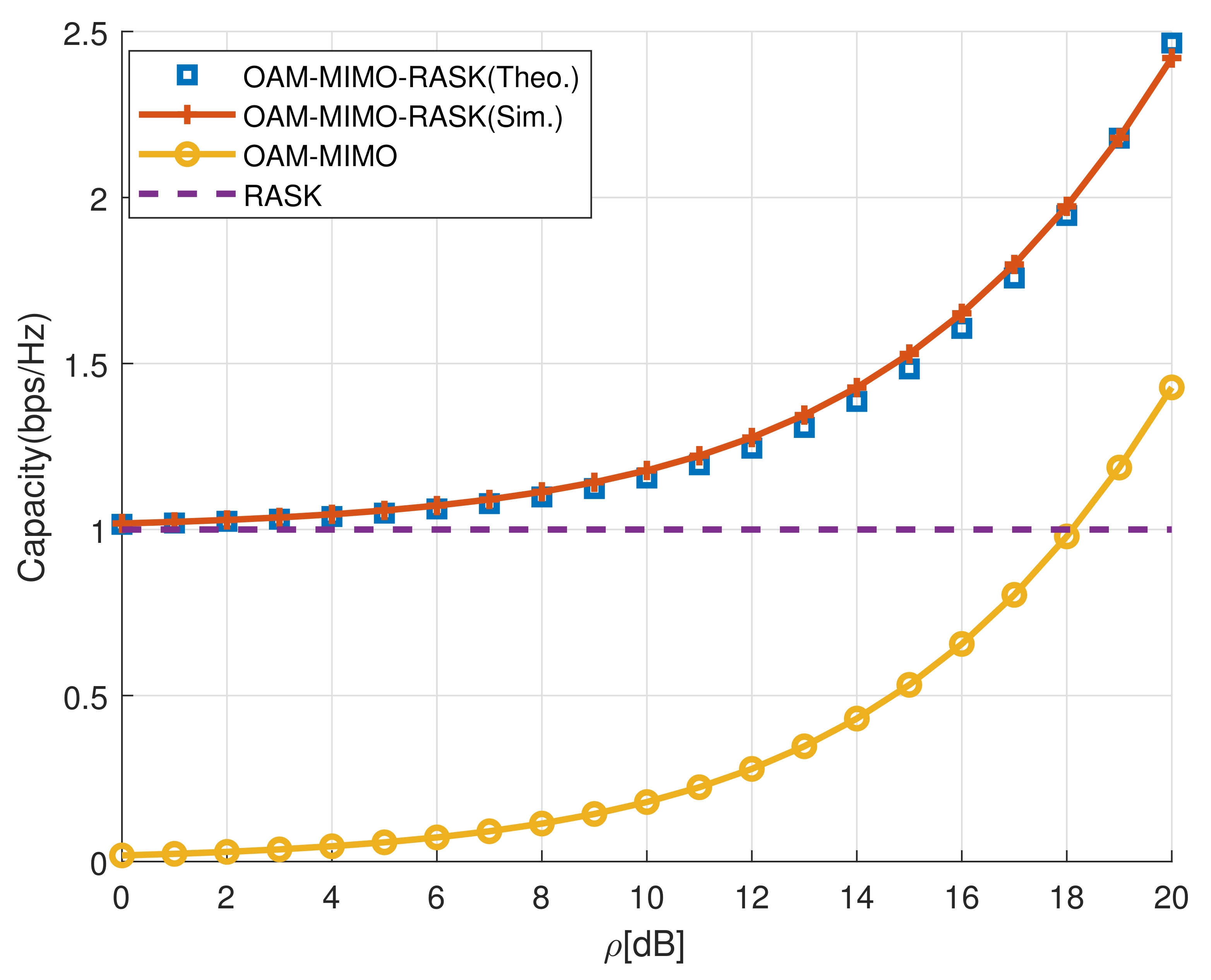
  • The Rx channel capacities and SC are investigated in the case of the OAM-MIMO-RASK scheme and compared with existing OAM-MIMO and RASK-based schemes by simulation results. The simulation result of SC for the OAM-MIMO-RASK scheme is validated by the theoretical result.
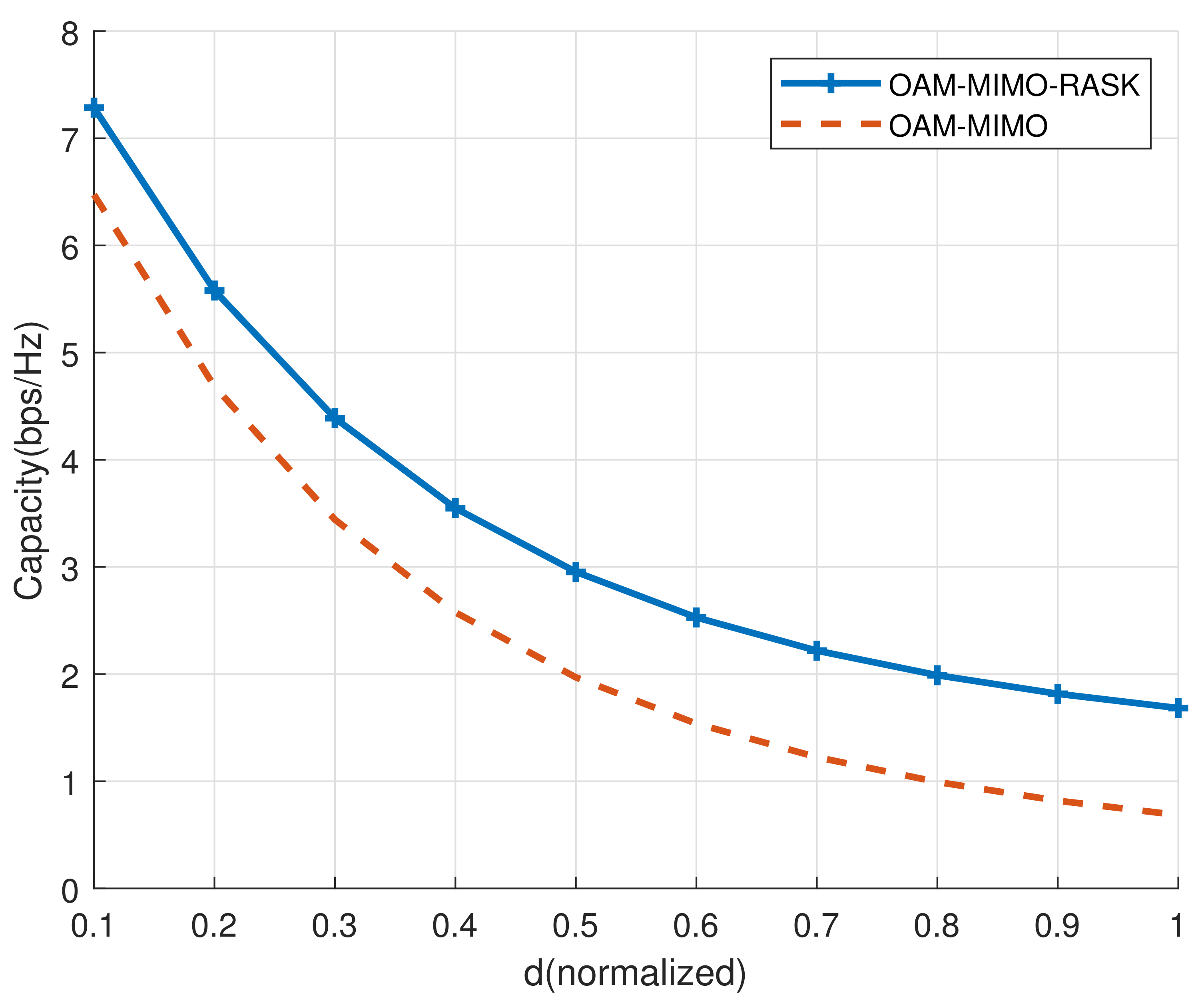
  • The impact of the normalized distance between Txs and Rxs for the OAM-MIMO-RASK scheme is investigated and compared with other conventional schemes by simulation results.
The remainder of this paper is assembled as below. The system architecture along with the system model of the OAM-MIMO-RASK scheme are explained in Section 2. Section 3 described the channel capacity analysis of the OAM-MIMO-RASK scheme. Section 4 illustrated and described the numerical results. The concluding statements are provided in Section 5. Table 1 lists the major abbreviations which are mentioned right through the paper.

2. System Model and System Architecture

The system model along with the system architecture of the DL OAM-RASK scheme are illustrated in Figure 1. The proposed OAM-MIMO-RASK system model comprises a base station (BS) as the source (S) and one user equipment ( U E ). The RASK-based system comprises multiple transmit and received antennas. Hence, S comprises multiple transmitters, denoted as T x 1 and T x N . Moreover, U E comprises multiple receivers, denoted as R x 1 and R x M . T x 1 and T x 2 are directly transmitted to R x 1 and R x 2 concurrently. The proposed system model is considered with perfect channel-state information for all transmissions. Non-coaxial Tx UCAs non-coaxial Rx UCAs are considered at S and U E , accordingly. All Tx and Rx consist of UCAs. Moreover, d is the distance from the UCA center of the Tx UCAs to the center of the Rx UCAs. Moreover, the number of non-coaxial T x 1 UCAs at S is N 1 ( n 1 = 1 , 2 , . . . . , N 1 ) and the number of non-coaxial T x N UCAs at S is N T ( n N = 1 , 2 , . . . . , N T ). Likewise, the quantity of the non-coaxial Rx UCAs at R x 1 and R x M are M 1 ( m 1 = 1 , 2 , . . . . , M 1 ) and M T ( m M = 1 , 2 , . . . . , M T ), respectively [13,27,28,29]. According to the concept of RASK, N 1 denotes the total number of active UCAs as well as OAM modes at T x 1 . Moreover, N T symbolized the total number of active OAM modes and UCAs at T x N . Furthermore, the amount of non-coaxial Rx UCAs at R x 1 and R x M are denoted as M 1 ( m 1 = 1 , 2 , . . . . , M 1 ) and M T ( m M = 1 , 2 , . . . . , M T ), respectively [13,27,28,29]. The total number of active OAM modes at T x 1 and T x N are denoted as N 1 and N T , respectively. Moreover, d 1 ( m 1 , n 1 ) and d 2 ( m 2 , n 1 ) symbolize the distances from the n 1 t h ( 1 n 1 N 1 ) Tx UCA of S ( T x 1 ) to the m 1 t h ( 1 m 1 M 1 ) R x 1 UCA of U E and m M t h ( 1 m M M T ) R x 2 UCA of U E , respectively [29]. In addition, d 1 ( m 1 , n N ) and d N ( m M , n N ) denote the distances from the n N t h ( 1 n N N T ) Tx UCA of S ( T x N ) to the m 1 t h ( 1 m 1 M 1 ) Rx UCA of U E and m M t h ( 1 m M M T ) Rx UCA of U E , accordingly [29].
Moreover, T x 1 , T x N , R x 1 , and R x M are also considered for the proposed DL OAM-MIMO-RASK wireless communication system. In total, N symbolizes the number of transmitters and M symbolizes the number of receivers for the OAM-MIMO-RASK scheme which is proposed in this study. Furthermore, the N k unit of Tx UCAs generated N k number of OAM modes in the case of k, where { k ϵ 1 , . . . N } . Each active UCA of different transmitters simultaneously transmits an OAM wave based on the respective OAM mode with the same resources. Different OAM modes provide (IMI) and (ICI)-free independent subchannels [30]. Tx UCAs with an even index of all transmitters (for example, l 1 2 , ..., l 1 N 1 and l N 2 , ...., l N N T ) are transmitted toward R x 1 , and the Tx UCAs with an odd index of all transmitters (e.g., l 1 1 , ..., l 1 N 1 1 , and l N 1 , ... l N N T 1 ) are transmitted toward R x M , simultaneously, which is illustrated in Figure 1. Consequently, the OAM wave with even OAM modes is received by R x 1 , and the OAM wave with odd modes are received by R x M , respectively, with the OAM-MIMO-RASK scheme through the channel with zero-mean-circular symmetric complex Gaussian (ZMCSCG) noise. According to the principle of OAM-MIMO, S conveys an OAM signal χ k n k = P l k n k x n k by the OAM mode l k n k . Where x n k symbolize the data symbols and P l k n k denote the power allocation factors for T x k . Moreover, P denotes the total transmit power ( P = k = 1 N k 1 = 1 N k P l k n k 2 ) from S [7,29,30,31]. Furthermore, the number of transmitted symbols from S are x 1 , . . . . . . , x W . In addition, symbols are evenly transmitted by the T x s conferring to the OAM-MIMO-RASK scheme. Hence, based on the concept of OAM-MIMO and RASK, l k n k denotes the amount of operative OAM modes which are conveyed from the n k t h UCA of the respective Tx at S [28]. Therefore, the antenna element n k ( n k ϵ { 1 , 2 , . . . . . . . , N k } ) is fed by the signals of different operating OAM modes which is expressed in (1) in the case of the proposed scheme [13,27,28]:
ξ k n k = ( χ k n k ) e j [ φ n k + α r n k ] , = ( χ k n k 1 ) e j [ ( 2 π ( n k 1 ) N k + α r n k ) ] l k n k .
where φ n k + α r n k symbolizes the azimuthal angle. Azimuthal angle represents the angular position over the plane which is perpendicular to the axis of propagation [28,29]. The values of φ n k can vary from 0 to 2 π , which depends on n k . According to Figure 1, α r n k and α R m p symbolizes the angles amid the phase angle and the corresponding array element. Furthermore, α r n k and α R m p are associated with the UCAs of Tx and Rx of the OAM-MIMO-RASK scheme [28,29]. Moreover, θ k symbolizes the combined angle amid the projection line which is originating from the center point of the Tx UCA towards the center point of the Rx UCA above the plane of transmission and the x-axis. The combined angle amid the line which is originating from the center point of the Tx UCA towards the center point of the UCA in the case of the respective Rx and the z-axis. The combined angle is denoted by ϕ n k (Due to the misalignment of transmitters ( T x 1 / T x N ) to the receivers at misaligned position ( R x M / R x 1 ).) [11,28,29]. Moreover, ϕ n k is denoted as misalignment angle in this study. Furthermore, r n k represents the radius of the Tx UCA at S. In addition, R m p ( { p } ϵ { 1 , . . . . . M } ) symbolizes the radius associated with the Rx UCA. In the case of Rx UCAs, the elements of the UCAs are assumed to be uniform around the circle’s perimeter. The channel matrix of the proposed OAM-MIMO-RASK scheme is expressed by the following equations [13,28,29]:
h i , j ( m p , n k ) = A m p e j [ B m p sin ( φ n k + α r n k ψ m p a R m p + ζ m p ) ] ,
where
A m p = β λ 4 π ( d i , j 2 + r n k 2 + R m p 2 ) e j 2 π ( d i , j 2 + r n k 2 + R m p 2 ) λ e [ j 2 π R m p d i , j s i n ϕ n k cos ( ψ m p + a R m p θ k ) λ ( d i , j 2 + r n 2 + R m p 2 ) ]
B m p = 2 π r n R m p 2 + d i , j 2 sin 2 ϕ n k 2 R m k d i , j s i n ϕ n k cos ( ψ m p + a R m p θ n k ) λ ( d i , j 2 + r n 2 + R m p 2 ) .
Moreover, ψ m p = 2 π ( m p 1 ) / M p represents the basic angle of the received UCA. The attenuation and phase rotation caused by antennas and their patterns on both sides are denoted by β .
Furthermore,
sin ζ m p = R d i , j sin ϕ n k c o s ( ψ m p + a R m p θ n k ) R m p 2 + d i , j 2 sin 2 ϕ n k 2 R m p d i , j s i n ϕ n k cos ( ψ m p + a R m p θ n k )
and
cos ζ m p = d i , j sin ϕ p c o s ( ψ m p + a R m p θ n k ) R m p 2 + d i , j 2 sin 2 ϕ n k 2 R m p d i , j s i n ϕ n k cos ( ψ m p + a R m p θ n k )
In addition, { i , j } ϵ { T x k , R x p } . The signals were transmitted through the subchannels by using various independent OAM waves. The OAM waves from the respective Tx are transmitted toward the respective receiver by using the RASK concept. Individual OAM wave is generated by individual OAM modes ( l k n k ) from the respective Tx. Each Tx UCA transmits the same amount of power and has similar eigenvalues [10,28]. Various independent and uncorrelated subchannels based on various OAM modes l k n k (OAM wave) are originated by the n k t h UCA which is situated at S. At the same time, the OAM wave is received by the respective m p t h UCA which is situated at U E [28,29]. To overcome ICI and IMI, the OAM modes are assumed by the mode combination technique which is shown in Table 2 [13]. An individual signal ( χ k n k ) is transmitted to U E by using the individual uncorrelated subchannel and individual OAM waves (based on l k n k ). At the same time, all OAM waves with even OAM modes are transmitted toward R X 1 , and all the OAM waves with odd OAM modes are transmitted to R X M by using the RASK principle.
To decode the respective signals at U E , mode decomposition (MD) was applied to the received signal by each UCA. By using the MD and signal decoding at the U E , the individual transmit signals for the proposed OAM-MIMO-RASK scheme are recovered for the respective Rx UCAs which is shown in Figure 1 [10,28].
Thus, the achievable signal-to-interference-and-noise ratios in the case of R x 1 and R x M are expressed as below:
γ 1 = m 1 = 1 M 1 n 1 = 2 ( n 1 o d d ) N 1 ρ | h T x 1 , R x 1 ( m 1 , n 1 ) | 2 + n = 2 ( n 2 o d d ) N 2 ρ | h T x 2 , R x 1 ( m 1 , n 2 ) | 2 ,
γ M = m 2 = 1 M T n 1 = 2 ( n 1 e v e n ) N 1 ρ | h T x 1 , R x M ( m M , n 1 ) | 2 + n = 2 ( n N e v e n ) N T ρ | h T x N , R x M ( m M , n N ) | 2 ,
where ρ = P σ 2 represents the transmit SNR. Furthermore, the received signal at R x 1 and R x M of U E can be expressed by the following equations:
y 1 = m 1 = 1 M 1 / 2 n 1 = 2 ( ( n 1 o d d ) ) N 1 χ 1 n 1 h T x 1 , R x 1 ( m 1 , n 1 ) e j 2 π ( n 1 1 ) N 1 l 1 n 1 + n N = 2 ( ( n N o d d ) ) N T χ N n N h T x N , R x 1 ( m 1 , n N ) e j 2 π ( n N 1 ) N T l N n N + z m 1 ,
y M = m M = 1 M T / 2 n 1 = 1 ( ( n 1 e v e n ) ) N 1 χ l 1 n 1 h T x 1 , R x 1 ( m 1 , n 1 ) e j 2 π ( n k 1 ) N k l 1 n 1 + n N = 2 ( ( n N e v e n ) ) N T χ N n N h T x N , R x 1 ( m 1 , n N ) e j 2 π ( n N 1 ) N T l 2 n N + z m M ,
where z m 1 and z m M represents the ZMCSCG random noise components along with variances ( σ m 1 2 , and σ m M 2 ) and zero mean at the m 1 t h and m M t h receiver antennas of R x 1 and R x M , respectively. Moreover, the signals detected via the MD technique for the OAM-MIMO-RASK scheme for an individual OAM mode ( l k n k ) can be achieved by following equations by R x 1 and R x M :
y 1 l 1 = M 1 g 1 χ 1 n 1 ,
y M l n M = M T g M χ N n N ,
where g p = N k β λ 4 π ( d 2 + r n k 2 + R m p 2 ) e j 2 π ( d 2 + r n k 2 + R m p 2 ) λ .

3. Capacity Analysis

The channel capacities of the OAM-MIMO-RASK scheme are investigated in this section.

3.1. Capacity Analysis of OAM-MIMO-RASK

As the proposed OAM-MIMO-RASK scheme is consists of M number of receiving UCAs. Therefore, the individual capacity of each receiving UCAs and SC are expressed in (13)–(15). Thus, the channel capacity of the R x 1 , R x M , and the SC of the receiving UCAs at U E are denoted as C 1 , C M , and C S C for the proposed scheme. Therefore, C 1 for R X 1 in the case of the OAM-MIMO-RASK scheme can be expressed as below:
C 1 = q 1 = 1 Q 1 log 2 ( 1 + γ 1 N 1 μ q 1 2 ) ,
As before, C M for R X M for the OAM-MIMO-RASK scheme can be achieved as below:
C M = q M = 1 Q M log 2 ( 1 + γ M N T μ q M 2 ) ,
As SC is the sum of all receiving UCAs and RASK capacity. Thus, SC of the OAM-MIMO-RASK scheme can be achieved as below:
C SC = C 1 + . . . . . + C M + l o g 2 ( M ) ,
where μ q 1 2 and μ q M 2 designate the eigenvalues corresponding to the channel matrices for R x 1 and R x M , accordingly. Moreover, Q 1 R 1 = m i n ( M 1 , N 1 , N T ) and Q M R M = m i n ( M T , N 1 , N T ) denote the ranks of the channel matrix from S. Moreover, full-rank ( Q 1 = R 1 ) and ( Q M = R M ) channel matrices with same eigenvalues are accomplished in this study [10,28].

3.2. Theoretical Capacity Analysis of OAM-MIMO-RASK

The theoretical capacity of R x 1 ( C 1 T ) and the theoretical capacity of R x M ( C M T ) are expressed by the equations below in the case of the OAM-MIMO-RASK scheme [32]:
C 1 T = M 1 log 2 ( 1 + ( ρ | h 1 | 2 ) ) ,
C M T = M T log 2 ( 1 + ( ρ | h 1 | 2 ) ) ,
Moreover, the theoretical capacity of SC ( C S T ) for the OAM-MIMO-RASK scheme can be expressed by the equations below [32]:
C S T = C 1 T + . . . . + C M T + l o g 2 ( M ) ,

4. Numerical Results

In this section, simulation results are presented to evaluate the performance of the OAM-MIMO-RASK scheme in terms of channel capacities and compared with conventional schemes (e.g., OAM-MIMO and RASK-based schemes). A MATLAB simulation was performed to evaluate the capacity of the proposed scheme and compare it with existing schemes. One S and one U E are considered for the proposed scheme and other compared schemes. The non-coaxial channel parameters are considered for the OAM-MIMO-RASK scheme and existing OAM-MIMO scheme [13,28,29].
The SC comparisons of the OAM-MIMO-RASK scheme and existing schemes are shown in Figure 2. The parameters r n k = n k λ , R m p = m p λ , λ = 0.01 , d = 20 λ , ϕ n 1 = ϕ n 2 = 45 , θ k = 0 , α r n = α R m k = 0 , P = 1 , N = M = 2 , and N k = M p = 4 are considered for the proposed OAM-MIMO-RASK scheme and compared conventional schemes for fair comparisons. The OAM-MIMO-RASK scheme provides a substantially SC improvement than the other compared conventional schemes for increasing values of ρ . Two transmitters and receivers are considered in this study because of the value of N and M ( N = M = 2 ). Due to the OAM-MIMO-RASK scheme, multiple Txs can transmit symbols simultaneously to the respective Rx UCAs without any interference issues by using different OAM modes which are generated by multiple respective UCAs at the Tx end. Each OAM mode is acted as an independent and uncorrelated subchannel by the mode combination technique. Individual independent subchannel carrying individual symbol to R x 1 . Similar to R x 1 , multiple Txs can transmit symbols simultaneously to the R x 2 without any interference issues by using different OAM modes which are generated by multiple respective UCAs at the Tx end. Each OAM mode is acted as an independent and uncorrelated subchannel. Individual independent subchannel carrying individual symbol to R x 2 . Moreover, additional information is transmitted towards the Rxs by RASK technique. However, SC is the sum of the receiver capacities ( C S C = C 1 + . . . . . + C M + l o g 2 ( M ) ). Thus, the proposed OAM-MIMO-RASK scheme anticipates notably improved SC than the existing schemes. Moreover, the simulation result is validated by the theoretical results for the OAM-MIMO-RASK scheme. In the case of the existing schemes, OAM-MIMO provides less capacity than the OAM-MIMO-RASK scheme because there is no additional information is transmitted towards the RXs which is shown in Figure 2. Moreover, Figure 2 illustrated that the existing RASK provides fixed capacity but less capacity than the proposed scheme because the capacity of RASK-based scheme is fixed and not dependent on SNR or bandwidth of the system [11]. However, the considered Tx and Rx UCAs of the proposed scheme should maintain the LOS communication because OAM-based communication can be possible when the Tx and Rx UCAs are maintaining LOS conditions.
The impact on SC for different values of normalized d is shown in Figure 3 and compared with conventional OAM-based schemes. The parameters r n k = n k λ , R m p = m p λ , λ = 0.01 , ρ = 20 dB, ϕ n 1 = ϕ n 2 = 45 , θ k = 0 , α r n = α R m k = 0 , P = 1 , N = M = 2 , and N k = M p = 4 are considered for the proposed OAM-MIMO-RASK and other schemes for fair comparisons. Owing to the higher values of d in the case of the OAM-based communication system, the attenuation increases as well owing to higher values of d. Thus, the capacity degrades significantly owing to the higher value of d for the proposed OAM-MIMO-RASK scheme compared with the conventional OAM-MIMO scheme. By using the OAM-MIMO-RASK scheme, multiple Tx conveys multiple symbols to the respective Rxs concurrently without any additional resource or interference issue by using various independent and uncorrelated OAM modes which are generated by individual UCAs at the Tx end by the mode combination technique. Each OAM mode is acted as an independent and uncorrelated subchannel. Individual independent subchannel carrying individual symbol to the respective Rxs. Furthermore, additional information is transferred to the Rxs using the RASK technique. Hence, the SC of the OAM-MIMO-RASK scheme is improved significantly in contrast to the existing OAM-MIMO-based scheme. In addition, the non-coaxial issue for the OAM-MIMO-RASK scheme is prevailed by the non-coaxial Tx and Rx UCAs. Hence, a significantly higher SC is attained for the OAM-MIMO-RASK scheme compared with the conventional OAM-MIMO-based scheme for different values of d which is illustrated in Figure 3. However, due to the divergence issue of the OAM beam, the SC is decreased exponentially due to the higher values of d for the proposed OAM-MIMO-RASK scheme which is also shown in Figure 3 [13]. Moreover, LOS communication between transmitters and receivers should be also maintained for the OAM-MIMO-RASK scheme.

5. Conclusions

In this study, multiple transmitters and receivers-based wireless OAM-MIMO multiplexing-based communication system is considered. To improve the capacity, RASK is integrated with OAM-MIMO multiplexing in the proposed OAM-MIMO-RASK scheme. Numerical results show that the OAM-MIMO-RASK scheme outplayed other existing schemes (e.g., OAM-MIMO/RASK) regarding SC. Furthermore, the simulation results are verified by the theoretical result. Moreover, is it also illustrated that how RASK can improve the capacity of the receivers in the case of conventional OAM-MIMO-based communication systems. However, the non-line-of-sight and divergence are vital issues for the proposed OAM-MIMO-RASK scheme due to the distance between the transmitters and receivers.
The future works can be extended by considering the multi-user access of the proposed scheme in a 6G multi-cell scenario. However, the user grouping, inter-user interference, inter-cell interference, and handover issues will be vital issues in the case of the OAM-MIMO-RASK scheme. In addition, The non-line-of-sight and OAM beam divergence issues can be solved in the future by considering the non-line-of-sight OAM communication and the lens converged OAM beam, respectively.

Author Contributions

All authors conceived and proposed the research idea; All authors designed the experiments; A.A.A. and S.-H.L. performed the experiments. A.A.A., S.-H.L., and S.-Y.S. analyzed the experimental results; A.A.A. and S.-H.L. wrote the paper under the supervision of S.-Y.S. All authors have read and agreed to the published version of the manuscript.

Funding

This work was supported by the National Research Foundation of Korea (NRF) grant funded by the Korea government (MSIT) (No. 2019R1A2C1089542).

Conflicts of Interest

The authors declare no conflict of interest.

References

  1. Cui, J.; Ding, Z.; Fan, P. Beamforming design for MISO non-orthogonal multiple access systems. IET Commun. 2016, 11, 720–725. [Google Scholar] [CrossRef]
  2. Zhang, Z.; Xiao, Y.; Ma, Z.; Xiao, M.; Ding, Z.; Lei, X.; Fan, P. 6G wireless networks: Vision, requirements, architecture, and key technologies. IEEE Veh. Technol. Mag. 2019, 14, 28–41. [Google Scholar] [CrossRef]
  3. Tamburini, F.; Mari, E.; Sponselli, A.; Thidé, B.; Bianchini, A.; Romanato, F. Encoding many channels on the same frequency through radio vorticity: First experimental test. New J. Phys. 2012, 14, 033001. [Google Scholar] [CrossRef]
  4. Yan, Y.; Xie, G.; Lavery, M.P.; Huang, H.; Ahmed, N.; Bao, C.; Willner, A.E. High-capacity millimetre-wave communications with orbital angular momentum multiplexing. Nat. Commun. 2014, 5, 1–9. [Google Scholar] [CrossRef] [PubMed] [Green Version]
  5. Ren, Y.; Li, L.; Xie, G.; Yan, Y.; Cao, Y.; Huang, H.; Willner, A.E. Experimental demonstration of 16 Gbit/s millimeter-wave communications using MIMO processing of 2 OAM modes on each of two transmitter/receiver antenna apertures. In Proceedings of the Global Communications Conference, Austin, TX, USA, 8–12 December 2014. [Google Scholar]
  6. Cheng, W.; Zhang, W.; Jing, H.; Gao, S.; Zhang, H. Orbital angular momentum for wireless communications. IEEE Wirel. Commun. 2018, 26, 100–107. [Google Scholar] [CrossRef] [Green Version]
  7. Wang, L.; Ge, X.; Zi, R.; Wang, C.X. Capacity analysis of orbital angular momentum wireless channels. IEEE Access 2017, 5, 23069–23077. [Google Scholar] [CrossRef]
  8. Lee, D.; Sasaki, H.; Fukumoto, H.; Hiraga, K.; Nakagawa, T. Orbital angular momentum (OAM) multiplexing: An enabler of a new era of wireless communications. IEICE Trans. Commun. 2017, 100, 1044–1063. [Google Scholar] [CrossRef] [Green Version]
  9. Lee, D.; Sasaki, H.; Fukumoto, H.; Yagi, Y.; Kaho, T.; Shiba, H.; Shimizu, T. An experimental demonstration of 28 GHz band wireless OAM-MIMO (orbital angular momentum multi-input and multi-output) multiplexing. In Proceedings of the 87th Vehicular Technology Conference (VTC Spring), Porto, Portugal, 3–6 June 2018. [Google Scholar]
  10. Opare, K.A.; Kuang, Y.; Kponyo, J. Mode combination in an ideal wireless OAM-MIMO multiplexing system. IEEE Wirel. Commun. Lett. 2015, 4, 449–452. [Google Scholar] [CrossRef]
  11. Phan-Huy, T.; Hélard, M. Receive antenna shift keying for time reversal wireless communications. In Proceedings of the International Conference on Communications (ICC), Ottawa, ON, Canada, 10–15 June 2012. [Google Scholar]
  12. Mokh, A.; Hélard, M.; Crussière, M. Extended receive antenna shift keying. In Proceedings of the 24th International Conference on Telecommunications (ICT), Jeju, Korea, 18–20 October 2017. [Google Scholar]
  13. Jing, H.; Cheng, W.; Zhang, W.; Lyu, R. OAM based wireless communications with non-coaxial UCA transceiver. In Proceedings of the 30th Annual International Symposium on Personal, Indoor and Mobile Radio Communications (PIMRC), Istanbul, Turkey, 8–11 September 2019. [Google Scholar]
  14. Zhou, C.; Gu, Y.; He, S.; Shi, Z. A robust and efficient algorithm for coprime array adaptive beamforming. IEEE Trans. Veh. Technol. 2017, 67, 1099–1112. [Google Scholar] [CrossRef]
  15. Ge, X.; Zi, R.; Xiong, X.; Li, Q.; Wang, L. Millimeter wave communications with OAM-SM scheme for future mobile networks. IEEE J. Sel. Areas Commun. 2017, 35, 2163–2177. [Google Scholar] [CrossRef] [Green Version]
  16. Garcia, C.E.; Camana, M.R.; Koo, I.; Rahman, A. Particle swarm optimization-based power allocation scheme for secrecy sum rate maximization in NOMA with cooperative relaying. In Proceedings of the International Conference on Intelligent Computing, Nanchang, China, 3–6 August 2019. [Google Scholar]
  17. Garcia, C.E.; Camana, M.R.; Koo, I. Secrecy energy efficiency maximization in an underlying cognitive radio–NOMA system with a cooperative relay and an energy-harvesting user. Appl. Sci. 2020, 10, 3630. [Google Scholar] [CrossRef]
  18. Garcia, C.E.; Camana, M.R.; Koo, I. Particle swarm optimization-based secure computation efficiency maximization in a power beacon-assisted wireless-powered mobile edge computing NOMA system. Energies 2020, 13, 5540. [Google Scholar] [CrossRef]
  19. Zhao, N.; Li, X.; Li, G.; Kahn, J.M. Capacity limits of spatially multiplexed free-space communication. Nat. Photonics 2015, 9, 822–826. [Google Scholar] [CrossRef]
  20. Zhang, C. Comparison of 5G oriented non orthogonal multiple access technologies. Telecommun. Netw. Technol. 2015, 11, 42–49. [Google Scholar]
  21. Zhang, Y.; Feng, W.; Ge, N. On the restriction of utilizing orbital angular momentum in radio communications. In Proceedings of the 8th International Conference on Communications and Networking in China (CHINACOM), Guilin, China, 14–16 August 2013. [Google Scholar]
  22. Gibson, G.; Courtial, J.; Padgett, M.J.; Vasnetsov, M.; Pas’ko, V.; Barnett, S.M.; Franke-Arnold, S. Free-space information transfer using light beams carrying orbital angular momentum. Opt. Express 2004, 12, 5448–5456. [Google Scholar] [CrossRef] [PubMed] [Green Version]
  23. Olver, A.D. Millimetrewave Systems—Past, Present and Future. Available online: https://sci-hub.se/10.1049/ip-f-2.1989.0006 (accessed on 11 May 2021).
  24. Hui, X.; Zheng, S.; Chen, Y.; Hu, Y.; Jin, X.; Chi, H.; Zhang, X. Multiplexed millimeter wave communication with dual orbital angular momentum (OAM) mode antennas. Sci. Rep. 2015, 5, 1–9. [Google Scholar] [CrossRef] [Green Version]
  25. Yao, A.M.; Padgett, M.J. Orbital angular momentum: Origins, behavior and applications. Adv. Opt. Photonics 2011, 3, 161–204. [Google Scholar] [CrossRef] [Green Version]
  26. Ren, Y.; Li, L.; Xie, G.; Yan, Y.; Cao, Y.; Huang, H.; Willner, A.E. Line-of-sight millimeter-wave communications using orbital angular momentum multiplexing combined with conventional spatial multiplexing. IEEE Trans. Wirel. Commun. 2017, 16, 3151–3161. [Google Scholar] [CrossRef]
  27. Zeng, M.; Yadav, A.; Dobre, O.A.; Tsiropoulos, G.I.; Poor, H.V. Capacity comparison between MIMO-NOMA and MIMO-OMA with multiple users in a cluster. IEEE J. Sel. Areas Commun. 2017, 35, 2413–2424. [Google Scholar] [CrossRef]
  28. Al Amin, A.; Shin, S.Y. Channel capacity analysis of non-orthogonal multiple access with OAM-MIMO system. IEEE Wirel. Commun. Lett. 2020, 9, 1481–1485. [Google Scholar] [CrossRef]
  29. Al Amin, A.; Shin, S.Y. Capacity enhancement of NOMA-MIMO with OAM-IM. IEEE Wirel. Commun. Lett. 2021, 10, 924–928. [Google Scholar] [CrossRef]
  30. Basar, E. Orbital angular momentum with index modulation. IEEE Trans. Wirel. Commun. 2018, 17, 2029–2037. [Google Scholar] [CrossRef]
  31. Wang, L.; Jiang, F.; Yuan, Z.; Yang, J.; Gui, G.; Sari, H. Mode division multiple access: A New scheme based on orbital angular momentum in millimetre wave communications for fifth generation. IET Commun. 2018, 12, 1416–1421. [Google Scholar] [CrossRef]
  32. Al Amin, A.; Shin, S.Y. Capacity Analysis of Cooperative NOMA-OAM-MIMO based Full-Duplex Relaying for 6G. IEEE Wirel. Commun. Lett. 2021. [Google Scholar] [CrossRef]
Figure 1. System Model and system architecture of DL OAM-MIMO-RASK.
Electronics 10 01567 g001
Figure 2. SC comparison between OAM-MIMO-RASK, OAM-MIMO, and RASK with respect to transmit SNR ( ρ ).
Electronics 10 01567 g002
Figure 3. SC comparison between OAM-MIMO-RASK and OAM-MIMO with respect to normalized distance (d).
Electronics 10 01567 g003
Table 1. Major abbreviations.
AbbreviationTerm
BSBase Station
DLDownlink
ICIInter-channel interference
IMIInter-mode interference
IoTInternet of things
LOSLine-of-sight
MDMode Decomposition
MIMOMultiple-input-multiple-output
mmWaveMillimeter-wave
OAMOrbital angular momentum
RASKReceive antenna shift keying
RxReceiver
SESpectral Efficiency
TxTransmitter
UCAUniform circular array
ZMCSGZero-mean-circular symmetric complex Gaussian
Table 2. Number of Tx and respective OAM modes via mode combination for the OAM-MIMO-RASK scheme.
CasesOAM Modes ( l k n k )Eigenvalues, μ q k 2
T X 1 −2, −1, 0, 14, 4, 4, 4
T X N 1, 3, 4, 64, 4, 4 ,4
Publisher’s Note: MDPI stays neutral with regard to jurisdictional claims in published maps and institutional affiliations.

