Communication

An Intrinsically Switched Tunable CABW/CFBW Bandpass Filter

School of Electronics & Information, Hangzhou Dianzi University, Hangzhou 310018, China
*
Author to whom correspondence should be addressed.
Electronics 2021, 10(11), 1318; https://doi.org/10.3390/electronics10111318
Submission received: 6 May 2021 / Revised: 24 May 2021 / Accepted: 28 May 2021 / Published: 31 May 2021
(This article belongs to the Special Issue Microwave Devices Design and Application)

Abstract

:
In this paper, a novel intrinsically switched tunable bandpass filter based on a dual-mode T-shaped varactor-loaded resonator is presented. The varactors loaded in the T-shaped resonator are capable of efficiently tuning the resonant frequencies of the even and odd modes, as well as the transmission-zero frequency. Without any additional RF switches, the passband of the filter can be intrinsically switched off by adjusting the transmission zero to the resonant frequencies. In the switch-on state, the constant absolute bandwidth (CABW) or constant fractional bandwidth (CFBW) passband can be achieved by controlling the frequency space between the two resonances. For a demonstration, a 0.8–1.1 GHz intrinsically switched tunable bandpass filter with 74 MHz CABW or 8.5% CFBW was fabricated and tested. In the whole operating band with |S11| < 10 dB, the insertion losses for CABW and CFBW are better than 3.3 dB and 3 dB, respectively, and the isolations are better than 20 dB in the switch-off state. The measured results have a good agreement with simulated results, which verifies the design theory.

1. Introduction

Reconfigurable filters have been extensively applied in the frequency-agile and software-defined radio systems due to their adjustable operating performance [1,2]. To meet the requirement of having constant passband characteristics in the whole tuning range, center-frequency-tunable bandpass filters with CABW or CFBW have been reported. Two methods are always used to achieve CABW or CFBW. The first way is to control the coupling strength by using varactors or selecting a proper coupling region [3,4,5,6,7]. The other method is to control the distance between the in-band transmission poles [8,9].
To adapt to complex operating environment, reconfigurable filters with switching capability have aroused a wide attention recently. By using the pin diodes as switches, the proposed filters in [10,11,12,13,14] can be operated in four states. Through utilizing combinations of pin diodes and varactors, the center-frequency-tunable filters can be switched in on/off state or in high/low passband [15,16]. However, it is worth noting that switching the pin diodes requires extra control voltages.
In order to reduce the number of external control variables and simplify the control complexity, intrinsically switched tunable bandpass filters are proposed [17]. In these structures, the off states can be obtained by the tuning elements which are also used to tune the center frequencies, bandwidths or coupling coefficients. Normally, two typical methods are utilized to realize intrinsically switched function. One way to switch off the passband is by changing the varactors embedded between the resonators that can control the coupling coefficients of the filters [17,18,19]. However, the magnetic coupling between the resonators has to be generated in these works in order to cancel the negative electric coupling from the coupling varactors. The other efficient way is to use the transmission zeros to switch off the passbands constructed by the spacing between transmission zeros [20,21,22]. However, these bandpass filters require more cascaded bandstop filters to realize wide out-band suppression.
In this paper, a novel intrinsically switched tunable bandpass filter with CABW/CFBW properties based on dual-mode varactor-loaded T-shaped resonator is presented. The varactors, in which the resonant frequencies are able to be tuned, adjust the transmission zero and switch off the passband, simultaneously. In addition, a feature of tunable passband with CABW/CFBW can be achieved by controlling the resonant frequencies and the spacing between them. As a demonstration, a prototype of a 0.8–1.1 GHz tunable 74 MHz CABW or 8.5% CFBW filter with intrinsically switchable function is developed and characterized. The proposed design possesses multiple functions only realized by two control voltages, which can simplify the control complexity extensively.

2. Filter Design and Analysis

2.1. Transmission Line Model Analysis

The schematic diagram of the proposed filter is provided in Figure 1a, which consists of a dual-mode T-shaped resonant loaded with two types of varactors (C1 and C2) and a pair of feed lines. The capacitor Cb and resistor Rb are applied as dc block and dc bias, respectively.
Due to the symmetrical structure, the odd–even mode method is utilized to analyze the proposed filter [23,24]. In order to simplify the analysis process of the dual-mode T-shaped resonator, the basic transmission line model of the proposed resonator is presented in Figure 1b, ignoring the influences of Cb and Rb, where Y1, Y2 and Y3 are the characteristic admittances and θ1, θ2 and θ3 are the electrical lengths.
The odd- and even-mode equivalent circuits are illustrated in Figure 1c,d, respectively, the input admittances of the odd- and even- mode can be derived by the following equations:
Yodd1 = −jY1cotθ1 × 2πfC1/(−Y1cotθ1 + 2πfC1)
Yodd = −jY3cotθ3 + Yodd1
Yeven1 = Y3(Yodd1 + jY3tanθ3)/(Y3 + jYodd1tanθ3)
Yeven2 = (Y1/2)(j2πfC2 + jY2tanθ2)/(Y2 − 2πfC2tanθ2)
Yeven = Yeven1 + Yeven2
Under the resonance condition (Im (Yodd) = 0 and Im (Yeven) = 0), the resonant frequencies can be extracted by Equations (1)–(5). It can be observed that odd-mode resonant frequency fodd is only controlled by C1, and the even mode resonant frequency feven is determined by C1 and C2 at the same time. Moreover, the transmission zero produced by the shunt stub taped with C2 can be used not only to improve the selectivity of bandpass filter as the normal way but also to switch off the passband. The input admittance of the shunt stub taped with the varactor C2 can be derived by:
Yzero = Y2 (j2πfC2 + jY2tanθ2)/(Y2 − 2πfC2tanθ2)
From Equation (6), it is observed that the frequency of transmission zero fzero can be deduced under the condition (Y2 − 2πfC2tanθ2 = 0), which indicates that fzero can be adjusted by C2.
Table 1 shows the tuning ranges of feven and fodd with variation of C1 and C2. fodd is independently decided by C1, but feven is controlled by C1 and C2 simultaneously. With fodd fixed by C1, feven varies around fodd by tuning C2. As shown in Figure 2, by tuning C1 and C2, the specified frequency space between feven and fodd can be obtained. If fodd is fixed by C1, feven can be changed from greater than to less than fodd by adjusting C2, and fzero is changed in the same way. Therefore, there is a C2 such that fodd = feven = fzero for different C1 (fodd), as the point A shown in Figure 2, and the passband can be intrinsically switched off at 0.994 GHz when C1 = 1.1 pF and C2 = 6.9 pF.

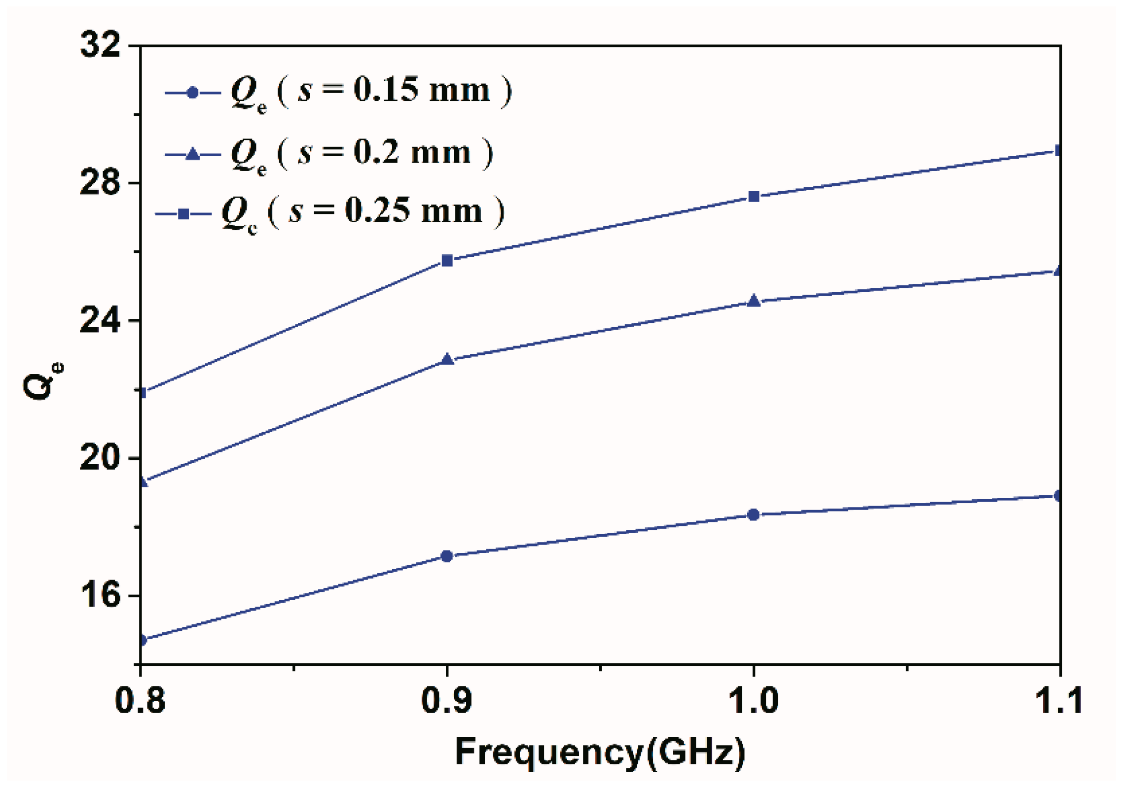
2.2. Analysis of fC, BW and Qe

According to the filter synthesis method in [25,26], the center frequency fC and bandwidth BW of the passband are estimated by Equations (7) and (8):
fC = (fodd + feven)/2
BW = fevenfodd
In Figure 3, the weak coupling transmission line responses are investigated. As indicated above, through tuning C1 and C2, the separation between fodd and feven can be suitable for 74 MHz CABW and 8.5% CFBW, respectively.
The external quality factor Qe of the proposed filter can be extracted by using [26]
Qeo/ee = fce/cofe/o±90°
Qe = (Qee + Qee)/2
where Qee/eo, fce/co and Δfe/o±90° are the even/odd mode external quality factors, resonant frequencies and bandwidths, respectively. In Figure 4, Qe,CABW,min/max and Qe,CFBW,min/max mean the minimum/maximum curves of Qe to realize 74 MHz CABW and 8.5% CFBW with <12 dB return loss, respectively [26].

2.3. Current Density Distribution Analysis

Current density distribution is employed to investigate the effect of being intrinsically switched off [27]. By utilizing the parameters of point A depicted in Figure 2, the filter is switched at 0.994 GHz, and the current density distribution is plotted in Figure 5. As seen, the T-shaped resonator does not allow flowing strong current, representing that the filter’ passband is switched off.

2.4. Designing Produce

The designing produces are as follows:
Step (1) Based on the analysis of even–odd mode and transmission zero, choose the appropriated admittances (Y1, Y2 and Y3), electrical lengths (θ1, θ2 and θ3), and varactors (C1 and C2) and calculate the fC and BW to make sure that the tuning range of fodd, feven and fzero can meet the design requirements of the filter.
Step (2) Calculate the Qe in the tuning range needed for specified return loss and bandwidth.
Step (3) Simulate and extract the Qe in the whole tuning under different space s between the resonant and the feedline.
Step (4) Choose the proper s.

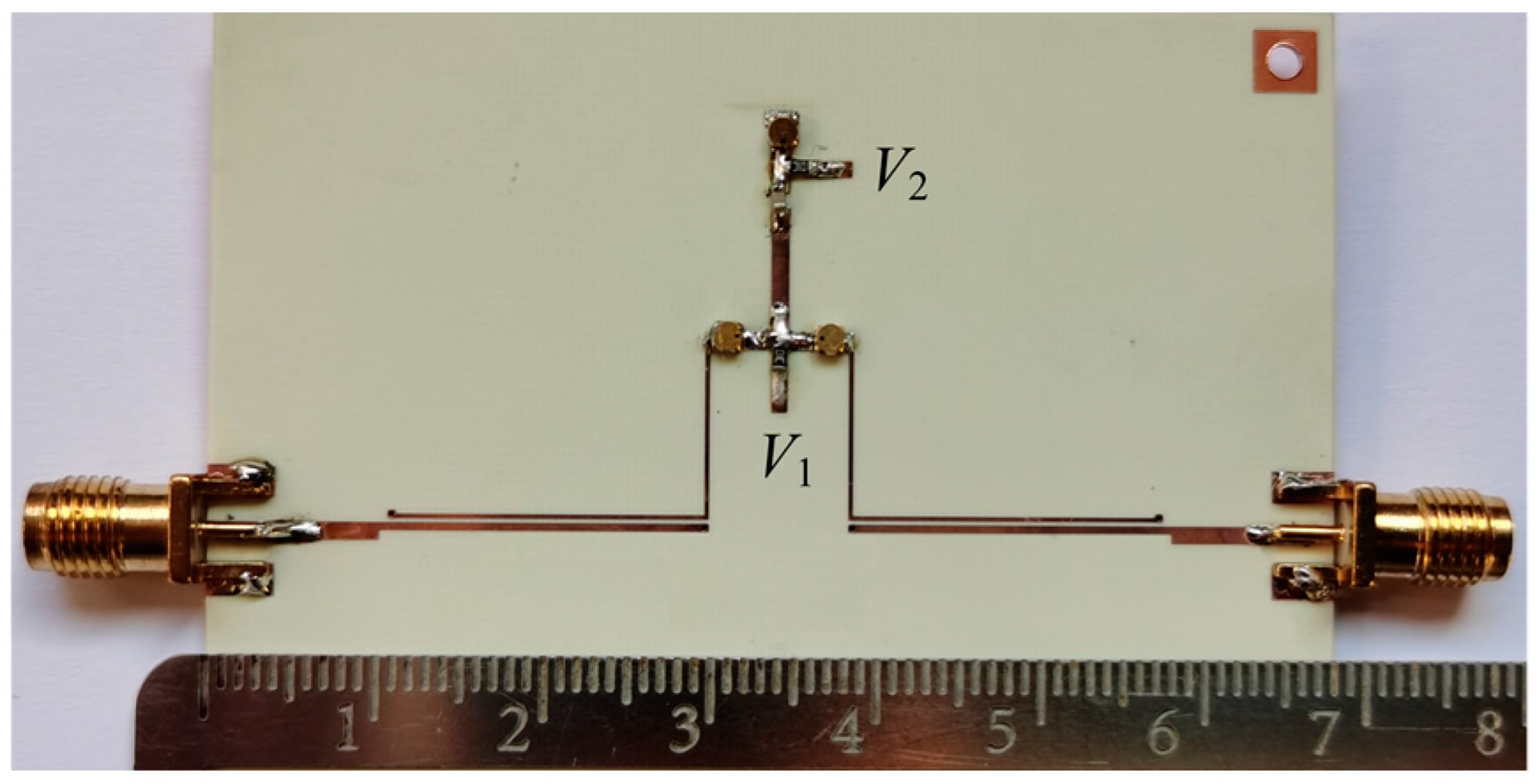
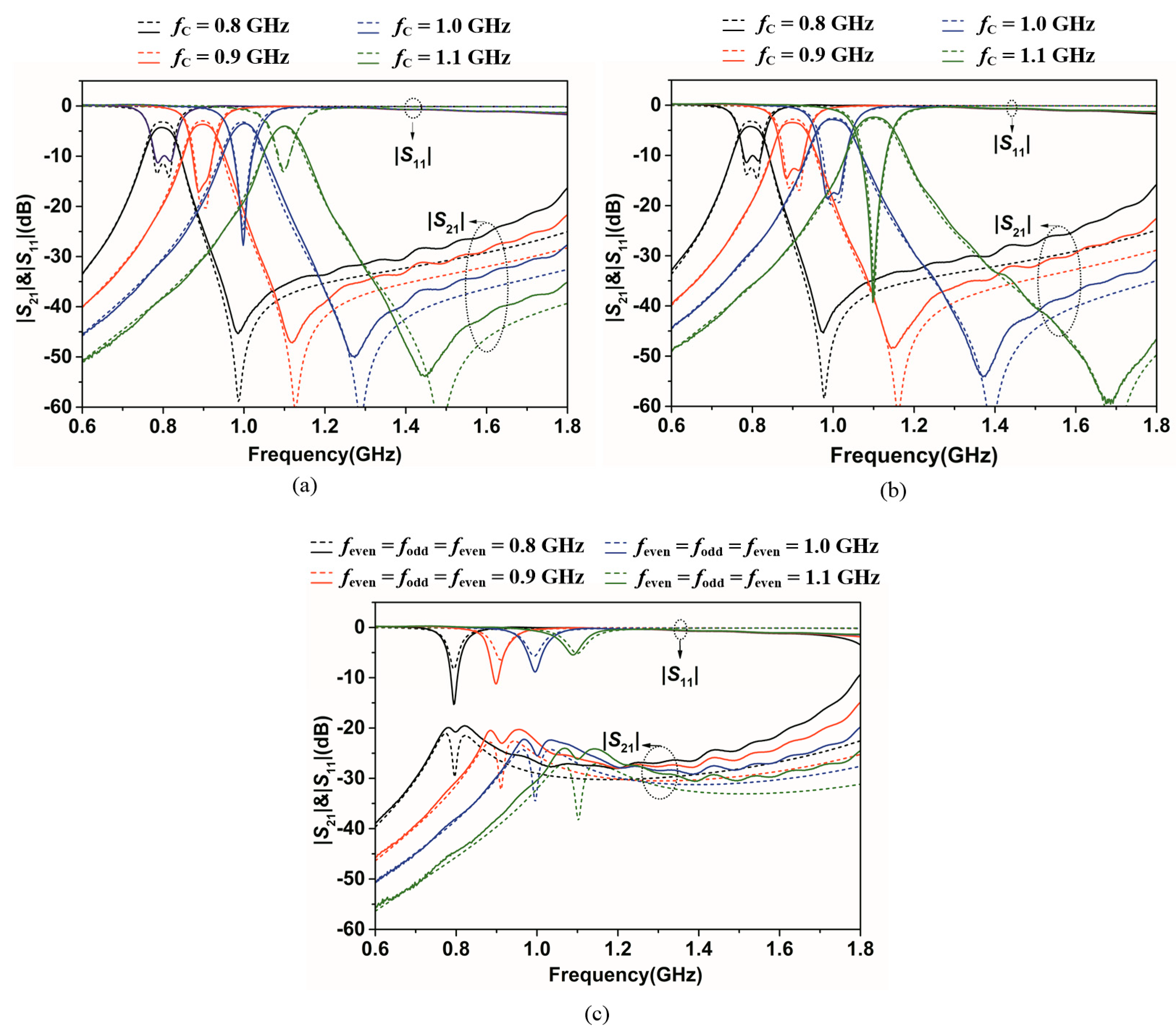
3. Experimental Verification

An intrinsically switched tunable filter is designed based on a 0.508 mm thick Rogers RO4350B substrate with a relative dielectric constant of 3.48 and a loss tangent of 0.0037, where the fC is tuned in the range of 0.8–1.1 GHz and the bandwidth satisfies 74 MHz CABW or 8.5% CFBW. The design parameters of the T-shaped resonant are chosen as Y1 = 0.01 S, Y2 = 0.02 S, Y3 = 0.02 S, θ1 = 60°, θ2 = 22° and θ3 = 5° at 1 GHz. By Equations (9) and (10), the filter’s Qe versus fC with different s are extracted in Figure 6, where s is the spacing between resonant and feed line in Figure 1a. It is noteworthy that, with s in range of 0.2–0.25 mm, the values of Qe basically meet the requirements for 74 MHz CABW and 8.5% CFBW shown in Figure 4 at the same time.
The simulations are conducted by using SONNET software. After optimization, the physical parameters of the filter are determined as in Table 2. The varactors MA46H201 (the capacitance tuning range is about 0.4–2.2 pF) and MA46H204 (the capacitance tuning range is about 1.8–20 pF) from M/A COM are employed as C1 and C2, which are controlled by voltages V1 and V2, respectively. Cb = 30 pF and Rb = 10 kΩ are used as dc block and dc bias, respectively. The photograph of the proposed intrinsically switched tunable filter is displayed in Figure 7. The prototype circuit size of the proposed filter is about 0.31 λg × 0.11 λg, where λg is the guided wavelength at the lowest operating frequency (i.e., 0.8 GHz). The measurements are carried out by the ROHDE&SCHWARZ ZVA24 network analyzer.
The simulated and measured frequency responses of the proposed prototype with three reconfigurable states are shown in Figure 8. Figure 8a,b depicts the tuning of the center frequency from 0.8–1.1 GHz with 74 MHz CABW and 8.5% CFBW, respectively. It also can be seen that a transmission zero on the upper band edge increases as the center frequency increases in both Figure 8a,b. The measured 3 dB bandwidth of the CABW filter and 3 dB fractional bandwidth of the CFBW filter are 74 ± 1 MHz and 8.5 ± 0.1%, respectively. The measured insertion losses of the CABW filter and the CFBW filter are better than 3.3 dB and 3 dB, respectively, with measured return losses better than 10 dB. Figure 8c presents the responses of passband in intrinsic switch-off state. As shown, the passband can be switched off at 0.8–1.1 GHz by tuning C1 and C2, and the measured isolations are all better than 20 dB. Comparisons with the previously reported switched tunable filter are listed in Table 3. As can be seen, the proposed filer has all the functions of tuning the center frequency, controlling the bandwidth (CABW and CFBW) and switching off the passband, simultaneously. Moreover, it is worth noting that the number of control voltages used in this work is equal to the order of the filter, which can reduce the control complexity of the design.

4. Conclusions

A novel intrinsically switched tunable filter based on dual-mode T-shaped resonator embedded with varactors is proposed in this paper. The theoretical basis and characterization of proof-of-concept microstrip prototype have been shown. The proposed filter controlled by only two voltages has the reconfigurable ability of center-frequency tuning, bandwidth controlling and passband intrinsically switching. The proposed filter has the potentiality to be applied in multiband communication systems and reduce its control complexity.

Author Contributions

Conceptualization, T.D. and B.G.; Experiment, T.D. and Y.G.; writing—original draft preparation, T.D.; writing—review and editing, D.W.; supervision, P.Z.; funding acquisition, P.Z. All authors have read and agreed to the published version of the manuscript.

Funding

This work was supported by the National Natural Science Foundation of China, grant number 61501153 and 61801153, State Key Laboratory of Millimeter Waves under grant number K202012 and Natural Science Foundation of ZheJiang Province under grant number LQY20F010001.

Conflicts of Interest

The authors declare no conflict of interest.

References

  1. Liu, X. Tunable RF and microwave filters. In Proceedings of the 2015 IEEE 16th Annual Wireless and Microwave Technology Conference (WAMICON), Cocoa Beach, FL, USA, 13–15 April 2015; pp. 1–5. [Google Scholar]
  2. Psychogiou, D.; Peroulis, D. Reconfigurable bandpass filter with center frequency and bandwidth control. Microw. Opt. Technol. Lett. 2013, 55, 2745–2750. [Google Scholar] [CrossRef]
  3. Chi, P.L.; Yang, T.; Tsai, T.Y. A Fully tunable two-pole bandpass filter. IEEE Microw. Wirel. Compon. Lett. 2015, 25, 292–294. [Google Scholar] [CrossRef]
  4. Kumar, N.; Singh, Y.K. Compact constant bandwidth tunable wideband BPF with second harmonic suppression. IEEE Microw. Wirel. Compon. Lett. 2016, 26, 870–872. [Google Scholar] [CrossRef]
  5. Cai, J.; Chen, J.X.; Zhang, X.F.; Yang, Y.J.; Bao, Z.H. Electrically varactor-tuned bandpass filter with constant bandwidth and self-adaptive transmission zeros. IET Microw. Antennas Propag. 2017, 11, 1542–1548. [Google Scholar] [CrossRef] [Green Version]
  6. Gao, L.; Rebeiz, G.M. A 0.97–1.53-GHz tunable four-oole bandpass filter with four transmission zeroes. IEEE Microw. Wirel. Compon. Lett. 2019, 3, 1–3. [Google Scholar]
  7. Chen, C.F.; Wang, G.Y.; Li, J.J. Microstrip switchable and fully tunable bandpass filter with continuous frequency tuning range. IEEE Microw. Wirel. Compon. Lett. 2018, 28, 500–502. [Google Scholar] [CrossRef]
  8. Luo, X.; Sun, S.; Staszewski, R.B. Tunable bandpass filter with two adjustable transmission poles and compensable coupling. IEEE Trans. Microw. Theory Tech. 2014, 62, 2003–2013. [Google Scholar] [CrossRef] [Green Version]
  9. Jung, M.; Min, B.W. A widely tunable compact bandpass filter based on a switched varactor tuned resonator. IEEE Access. 2019, 7, 95178–95185. [Google Scholar] [CrossRef]
  10. Dai, G.L.; Xia, M.Y. Design of compact dual-band switchable bandpass filter. Electron. Lett. 2009, 45, 506–507. [Google Scholar] [CrossRef]
  11. Tu, W.H. Design of switchable dual-band bandpass filters with four states. IET Microw. Antennas Propag. 2010, 4, 2234–2239. [Google Scholar] [CrossRef]
  12. Deng, D.P.; Jheng, J.H. A switched reconfigurable high-isolation dual-band bandpass filter. IEEE Microw. Wirel. Compon. Lett. 2011, 21, 71–73. [Google Scholar] [CrossRef]
  13. Deng, P.H.; Tsai, J.T.; Liu, R.C. Design of a switchable microstrip dual-band lowpass-bandpass filter. IEEE Microw. Wirel. Compon. Lett. 2014, 24, 599–601. [Google Scholar] [CrossRef]
  14. Abdalla, M.A.; Choudhary, D.K.; Chaudhary, R.K. A compact reconfigurable bandpass/lowpass filter with independent transmission zeros based on generalized NRI metamaterial. Int. J. RF Microw. Comput. Aided Eng. 2019, 30, e22074. [Google Scholar] [CrossRef]
  15. Zhang, Y.; Cai, J.; Chen, J. Design of novel reconfigurable filter with simultaneously tunable and switchable passband. IEEE Access. 2019, 7, 59708–59715. [Google Scholar] [CrossRef]
  16. Lin, F.; Rais-Zadeh, M. Continuously tunable 0.55–1.9-GHz bandpass filter with a constant bandwidth using switchable varactor-tuned resonators. IEEE Trans. Microw. Theory Tech. 2017, 65, 792–803. [Google Scholar] [CrossRef]
  17. Guyette, A.C. Intrinsically switched varactor-tuned filters and filter banks. IEEE Trans. Microw. Theory Tech. 2012, 60, 1044–1056. [Google Scholar] [CrossRef]
  18. Cho, Y.; Rebeiz, G.M. Tunable 4-pole noncontiguous 0.7–2.1-GHz bandpass filters based on dual zero-value couplings. IEEE Trans. Microw. Theory Tech. 2015, 63, 1579–1586. [Google Scholar] [CrossRef]
  19. Yang, T.; Rebeiz, G.M. Tunable 1.25–2.1-GHz 4-pole bandpass filter with intrinsic transmission zero tuning. IEEE Trans. Microw. Theory Tech. 2015, 63, 1569–1578. [Google Scholar] [CrossRef]
  20. Psychogiou, D.; Gómez-García, R.; Peroulis, D. Tune-all RF planar duplexers with intrinsically switched channels. IEEE Microw. Wirel. Compon. Lett. 2017, 27, 350–352. [Google Scholar] [CrossRef]
  21. Psychogiou, D.; Gómez-García, R.; Peroulis, D. Fully-reconfigurable bandpass/bandstop filters and their coupling-matrix representation. IEEE Microw. Wirel. Compon. Lett. 2016, 26, 22–24. [Google Scholar] [CrossRef]
  22. Gómez-García, R.; Muñoz-Ferreras, J.; Psychogiou, D. Dual-behavior resonator-based fully reconfigurable input reflectionless bandpass filters. IEEE Microw. Wirel. Compon. Lett. 2019, 29, 35–37. [Google Scholar] [CrossRef]
  23. Ahmadi, A.; Makki, S.V.; Lalbakhsh, A.; Majidifar, S. A novel dual-mode wideband band pass filter. Appl. Comp. Electron. Soc. J. 2014, 29, 735–741. [Google Scholar]
  24. Lalbakhsh, A.; Karimi, G.; Sabaghi, F. Triple mode spiral wideband bandpass filter using symmetric dual-line coupling. Electron. Lett. 2017, 53, 795–797. [Google Scholar] [CrossRef]
  25. Serrano, A.L.C.; Correra, F.S.; Vuong, T.; Ferrari, P. Synthesis methodology applied to a tunable patch filter with independent frequency and bandwidth control. IEEE Trans. Microw. Theory Tech. 2012, 60, 484–493. [Google Scholar] [CrossRef]
  26. Lu, D.; Tang, X.; Barker, N.S.; Feng, Y. Single-band and switchable dual-/single-band tunable BPFs with predefined tuning range, bandwidth, and selectivity. IEEE Trans. Microw. Theory Tech. 2018, 66, 1215–1227. [Google Scholar] [CrossRef]
  27. Lalbakhsh, A.; Alizadeh, S.M.; Ghaderi, A.; Golestanifar, A.; Mohamadzade, B.; Jamshidi, M.; Mandal, K.; Mohyuddin, W. A Design of a Dual-Band Bandpass Filter Based on Modal Analysis for Modern Communication Systems. Electronics 2020, 9, 1770. [Google Scholar] [CrossRef]
Figure 1. (a) Schematic diagram of the proposed filter; (b) transmission line mode; (c) odd mode; and (d) even mode.
Electronics 10 01318 g001
Figure 2. feven, fodd and fzeroVersus C1 and C2. Y1 = 0.01S, Y2 = Y3 = 0.02S, θ1 = 55°, θ2 = 25° and θ3 = 5° at 1 GHz.
Electronics 10 01318 g002
Figure 3. Typical response using week couple (solid line: 74 MHz CABW case; dash line: 8.5% CFBW case).
Electronics 10 01318 g003
Figure 4. Desired Qe for 74 MHz CABW and 8.5% CFBW.
Electronics 10 01318 g004
Figure 5. Current density distribution of the proposed filter in switched-off state.
Electronics 10 01318 g005
Figure 6. Extracted Qe versus fC with different s.
Electronics 10 01318 g006
Figure 7. The photograph of the proposed filter.
Electronics 10 01318 g007
Figure 8. Simulated and measured S parameters for the proposed filter (solid line: measurement; dash line: simulation). (a) Center-frequency tuning with 74 MHz CABW; (b) center-frequency tuning with 8.5% CFBW; and (c) intrinsic switch-off state.
Electronics 10 01318 g008
Table 1. Tuning range of feven and fodd as C1 and C2 vary. Y1 = 0.01 S, Y2 = Y3 = 0.02 S, θ1 = 55°, θ2 = 25° and θ3 = 5° at 1 GHz.
C1 & C2 (pF)C1 = 0.6
C2 = 2–12
C1 = 1.1
C2 = 2–12
C1 = 1.6
C2 = 2–12
C1 = 2.2
C2 = 2–12
fodd (GHz)1.1880.9940.8700.754
feven (GHz)1.234–1.1461.097–0.9581.021–0.8500.957–0.764
Table 2. Physical parameters of the proposed filter.
ParameterValue (mm)ParameterValue (mm)
l118.4w10.5
l229.8w20.3
l32.5w31.1
l47.6w41.1
s0.22
Table 3. Comparisons with previously reported switched tunable filter.
Ref No.Filter OrderNumber of Control VoltagesIntrinsic SwitchingCenter-Frequency ControlBandwidth ControlIL in Passband (dB)Isolation in Off-State
(dB)
Size
( λ g 2 )
[15]23NoYesCABW2.52–4.08>43N.A.
[17]33YesYesCABW<5>500.090
[19]45YesYesTunable3.5–8.5>330.082
[22]-4YesYesTunable0.96>20N.A.
This work22YesYesCABW/CFBW<3.3>200.035
Publisher’s Note: MDPI stays neutral with regard to jurisdictional claims in published maps and institutional affiliations.

