Abstract
This study presents a non-linear cracked-hinge model for the post-cracking response of fiber-reinforced cementitious composites loaded in bending. The proposed displacement-based model follows a meso-mechanical approach, which makes it possible to consider explicitly the random distribution and orientation of the reinforcing fibers. Moreover, the model allows for considering two different fiber typologies whereas the cement matrix is modelled as a homogeneous material. The proposed mechanical model combines a fracture-based, stress-crack opening relationship for the cementitious matrix with generalized laws aimed to capture the crack-bridging effect played by the reinforcing fibers. These laws are derived by considering both the fiber-to-matrix bond mechanism and fiber anchoring action possibly due to hooked ends. The paper includes a numerical implementation of the proposed theory, which is validated against experimental results dealing with fiber-reinforced cement composites reinforced with different short fibers. The excellent theory vs. experiment matching demonstrates the high technical potential of the presented model, obtained at a reasonable computational cost.
1. Introduction
Fiber-reinforced cementitious composites (FRCCs) are a class of concrete-like material developed in the last two decades with the aim of mitigating the inherent fragility of concrete in tension [1]. Several types of fiber are currently adopted as spread reinforcement in FRCCs, which range from the very common steel fibers [2,3,4,5], to the ones either made of plastics [6] or, more recently, obtained from plants [7,8], or produced by recycling waste tires [9,10,11]. Moreover, FRCCs can also be produced by blending different types of fibers to produce a class of composites often referred to as hybrid-FRCCs (Hy-FRCCs) with the aim to mobilize a synergistic action from each fiber [12,13,14,15,16,17].
Plenty of experimental results are available in the literature, which demonstrate the capability of fibers to bridge cracks developing throughout a cement-based matrix and, hence, enhancing their post-cracking performance in compression [18], but especially in tension [19] and bending [20,21].
Quantitative measures and indices have been defined in well-established codes and guidelines [22,23,24,25,26,27] with the aim of characterizing the post-cracking response of FRCCs, especially in specimens subjected to either three- or four-point bending. Specifically, these toughness indices are determined on the experimentally obtained force-displacement curve, generally focusing on either the crack-mouth-opening-displacement (CMOD) or the crack-tip-opening-displacement (CTOD).
However, no theoretical model has proven capable so far of being able to predict these force-CMOD/CTOD curves, based solely on the properties of the matrix mixture and the type and amount of fibers.
Some theoretical models are available in the literature and these often follow the Smeared Crack approach, such as the flow theory of plasticity [28], continuum damage theories [29] and microplane formulations [30]. However, other models are based on the discrete crack approach and assume discontinuous displacement fields as part of either X-FEM procedures [31], interface elements [32], or lattice and particle approaches [33].
This paper proposes a meso-scale based model intended at taking into account explicitly the behavior of the two typical “phases” of FRCCs, namely the cement-based matrix and the spread fiber reinforcement phases, along with their interaction. The model kinematics is inspired to the so-called “cracked-hinge” approach [34,35], but the crack-bridging effect of fibers is explicitly simulated and the presence of two different fiber types is also considered. Moreover, the proposed model aims at reproducing explicitly the random spatial distribution and orientation of fibers inside the FRCC matrix. In this sense, the proposed model can be intended as an extension of the one proposed by [36], where the number of fibers (of the same type, mainly made of steel) crossing the opening crack was based on statistical considerations. Therefore, the proposed meso-mechanical model aims at predicting the post-cracking behavior of FRCCs subjected to bending, starting with the formulation of appropriate mechanical models of the matrix, fibers, and their interface.
2. Formulation of a Meso-Mechanical Cracked-Hinge Model
2.1. Geometric Definition and Main Kinematic Assumptions
The cement-based beam is schematized as a prism of length L, width b, and depth h. Then, a Cartesian reference system is set at the centroid of the gross section at mid-span of the beam. In addition, a transverse “notch” (whose depth is denoted with δ) is present at the midspan section (Figure 1).
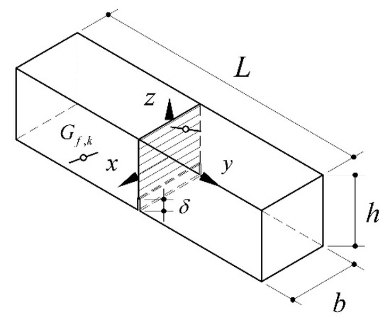
Figure 1.
Geometric scheme and definitions of the concrete beam.
Since the model aims at considering explicitly the contribution of the fiber-bridging effect across the two edges of cracks opening within the cementitious matrix, the model firstly generates the distribution of such fibers within the beam region. Specifically, as the total geometric ratio of fibers is defined ρf, along with both their diameter df and length lf, the total number of fibers nf can be easily determined:
where Vf is the volume of the fibers, Vfi is the volume of the single fiber, and Vc is the volume of the cement-based matrix.
It is worth highlighting that, if two different types of fibers are actually present within the matrix, their numbers nf,1 and nf,2 can be easily determined by means of Equation (1) considering the densities ρf,1 and ρf,2 of the materials they are made out of. However, for the sake of simplicity (and with no conceptual limitation) the formulation proposed hereafter is based on a single type of fibers.
Then, based on a random distribution within the prismatic beam volume, both the three centroidal coordinates xf,k, yf,k and zf,k (with k ranging between 1 and nf) and the two relevant angles αx,k and αz,k (Figure 2) can be randomly generated as follows:
where rnd(−0.5;+0.5) is a randomly generated real numbers included between −0.5 and 0.5. The coordinates of the two ends of the k-th fiber can be easily determined and the fiber position can be accepted if both ends are included within the beam prism.
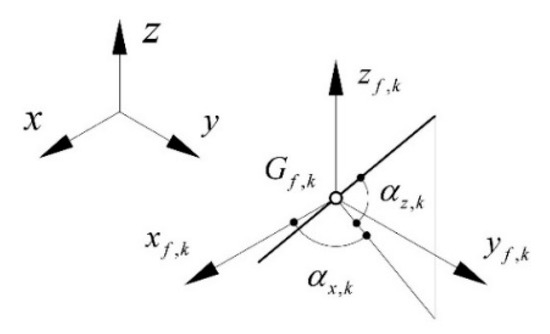
Figure 2.
Geometric parameters defining the position of the generic fiber within the concrete beam.
Although the various types of fibers considered in the FRCCs could not present constant geometrical characteristics, this formulation is restricted to assuming, for each type of fiber, invariant geometrical properties, such as diameter df (and, consequently section area Af), as well as length lf.
In a cracked-hinge model, it is accepted that flexibility is distributed in a portion s of the span length of the beam, while the remaining part is supposed to respond as a rigid body (Figure 3).
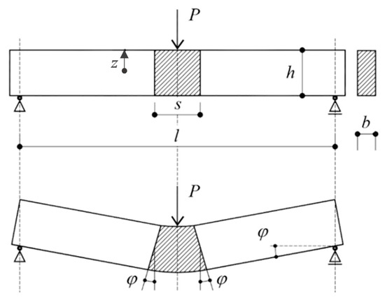
Figure 3.
Kinematics of the Cracked-Hinge Model.
The flexible part is modeled as an array of nc independent elastic springs or “strips” aligned with the longitudinal axis of the member (“strip model”) [34,35,36]. Whose force-displacement response is obtained by considering a “strip model” of the hinged region (Figure 4), and generalized constitutive relationships describing the stress release across the forming cracks and the extraction of fibers that bridge them.
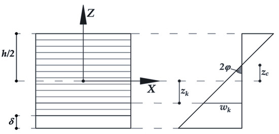
Figure 4.
Strip discretization of the notched cross section and resulting distribution of axial strains/displacements.
A simple kinematics can be established for the beam, if it is assumed that rotations of the two rigid blocks take place around the neutral axis of the cracked-hinge section, whose position is described by zc (Figure 4).
Based on this assumption, the rotation φ (Figure 3) can be taken as the main generalized displacement parameters, whereas the beam deflection at midspan v, the crack-tip opening displacement (CTOD), and the crack-mouth opening displacement (CMOD) can be determined as follows:
2.2. Equilibrium Equations
Equations (7)–(9) show that the position of the neutral axis (zc) plays a fundamental role in determining the relevant displacement components of the beam response in bending. For each value of the imposed rotation φ, the end points of a generic segment forming the “process zone” s (Figure 3) undergo the following relative axial displacement:
where z denotes the transverse coordinate of the strip (Figure 4).
Based on this observation, the present model assumes the following expressions of the axial displacement wk and the axial strain εk exhibited by the k-th strip (k = 1, …, nc):
The average axial stress σc,k across the k-th strip can be determined either as a function of the axial strain εk defined of Equation (12) (before cracking) or depending on the crack-opening displacements wk in Equation (11) (after cracking). Therefore, it depends on the position of the strip centroid zk and can be expressed as a function of both the neutral axis position zc and the imposed rotation φ as follows:
Details about the constitutive laws specifically adopted for the matrix in this study are described in Section 3.2.
As for the contribution of fibers, it is controlled by the crack opening displacement wk expressed in Equation (11). Moreover, the present formulation assumes a complete reorientation of fibers crossing the cracked section: regardless of their initial inclination (described by the angles αx,k and αz,k) they are supposed to exert axial stresses σf,k depending on both the lateral bond stress τ mobilized throughout the lateral area and the possible contribution F of the hooked end (see Section 3.3). Therefore, since both contributions depend on wk, the axial stress σf,k mobilized in the k-th fiber crossing the midspan section can be formally expressed as follows:
Therefore, the following equilibrium equation can be written for each imposed rotation angle φ:
and, hence, the position of the neutral axis can be determined. Therefore, the bending moment corresponding to the imposed rotation φ can be easily evaluated as follows:
3. Numerical Implementation
3.1. Geometry of the FRCC Beam
First of all, it is necessary to define some preliminary information, i.e., the geometry of the beam, in terms of L (length of the specimen assessed as the distance between the lower supports of the test machine), b and h (width and height of the specimen, respectively).
For the definition of the beam length, it is necessary to set the type of loading scheme, which can either be on three-points (L = 500 mm in accordance with the [22,23,24]) or four-points (L = 450 mm in accordance with the [25,26]). Then, the moment distribution can be easily determined.
Once the geometric characteristics of the beam have been defined, the discretization of the hinge formation zone is defined in a certain number of layers.
3.2. Stress-Strain and Stress-Crack Opening for Cementitous Matrix
According to the fictitious crack approach, a linear elastic behavior is assumed when the section is uncracked, while after the formation of the crack, a softening constitutive law is accepted where bridging stresses across the crack are defined in terms of the crack width.
For uncracked concrete, in accordance with [27], a bilinear stress–strain relation may be used, as given in the following equations:
where:
- -
- Ect is the tangent modulus of elasticity (expressed in MPa) in tension;
- -
- εct is the tensile strain,
- -
- σct is the tensile stress (expressed in MPa);
- -
- fctm is the tensile strength (expressed in MPa).
The Ect and fctm can be evaluated as follow [27]:
where Ec and fcm represent the elastic modulus and the mean cylindrical strength in compression, respectively [27].
The bilinear stress-strain relationship in Equation (17) describes the contribution of the matrix in tension before cracking. As the tensile strain εk of the generic matrix strip achieves the conventional value 0.00015 assumed as upper limit in in Equation (17b), a crack is supposed to open in that strip and, then, the residual stress σc,t has to be expressed as function of the crack opening w represented in Figure 5 [27]:
with:
where GF is the fracture energy which can be estimated as follow:
with GF0 and fcm0 equal to 0.11 N/mm and 10 MPa, respectively [27].
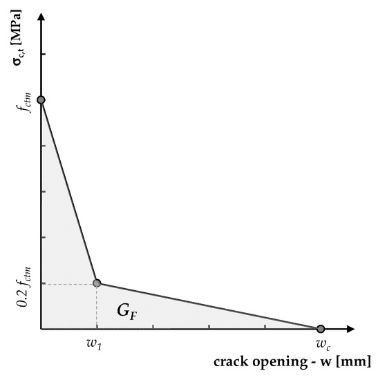
Figure 5.
Stress-crack opening relationship for cracked concrete.
3.3. Bond of Spread Fiber Reinforcement Embedded within the Cementitius Matrix
As for fibers, their response is supposed to result from the rigid body slipping of one of the two parts (actually, the shortest one) embedded in the two sides of the crack. Despite this, in the model proposed herein, it is assumed that the generic fiber intercepts the plane of formation of the crack exactly in the middle of its length, so that the unthreading conditions, on the right and left of the crack, are symmetrical. For the bond of the fibers, the two following contributions are considered (Figure 6):
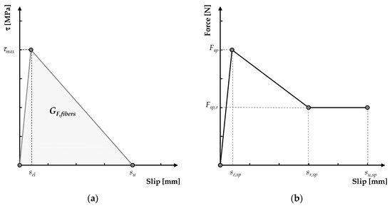
Figure 6.
Bond-slip law for short fibers embedded within the cementitious matrix: (a) longitudinal tangential stresses during slipping and (b) simulation of the hooked end.
- -
- the distributed bond throughout the lateral surface of the fiber, which is modelled through a bilinear bond-slip law (Figure 6a) which is defined by the three parameters τmax, sel and su and is governed by the fiber fracture energy (GF,fiber);
- -
- the concentrated force at the end hook (if present), which is described by a trilinear force-slip law (Figure 6b) defined by the maximum force Fsp attained at the slip se,sp, the residual force Fsp,r attained at a displacement sr,sp and sustained up to an ultimate slip value su,sp.
3.4. Force vs. Crack Opening Curves and Ductitlty Indices
Once the input parameters have been defined, it is possible to run the analysis by setting the number of simulations to be performed. Taking the input data above defined, the numerical procedure generates and positions the short fibers (Equations (1)–(6)). Subsequently, it assesses the stress reached in the cement-based matrix (by Equation (13)) as well as the contribution given by the fibers (by Equation (14)) in terms of strength. In this way, it is possible to define the position of the neutral axis (by Equation (15)) and, consequently, by integrating the axial tensions that arise on the cross section, the bending moment, through Equation (16). Finally, the load–displacement trend, expressed in terms of CMOD or CTOD, is simulated through the Equations (8) and (9).
The next step is the evaluation of the characteristic parameters defining the post-cracking response of the FRCCs. This is performed by introducing some ductility indices, by means of which it is possible to trace the numerical value of the areas underlying the load-CTOD curve, expression of the absorbed energy, and consequently, of the equivalent resistances and ductility indices.
More specifically, this evaluation is carried out as described by the UNI 11039/2003 [25,26] by introducing the following parameters: first crack strength (flf), work capacity indices (U1 and U2), the equivalent post-cracking strengths and ductility indices (D0 and D1)
The first crack strength (flf) is defined as follow:
where Plf represents the first crack load (in N).
The work capacity indices (U1 and U2) represent the areas under the vertical load P-CTOD curve in a representative range for the Serviceability Limit State (i.e., considering a CTOD ranging between CTOD0 and CTOD0 + 0.6 mm) and for the Ultimate State (i.e., considering CTOD ranges between CTOD0 + 0.6 mm and CTOD0 + 3.0 mm), respectively.
Regarding the two “equivalent post-cracking strengths” (feq(0–0.6) and feq(0.6–3)), the first is supposed to be relevant for the serviceability limit state (evaluated as a function of the U1 parameter), whereas the second one is relevant for the ultimate state (evaluated as a function of the U2 parameter).
Finally, the “ductility indices” (D0 and D1) can be determined with the following equations:
4. Model Validation
This section proposes a validation of the model based on experimental results already available in the literature, either in terms of applied force vs. crack-opening displacements (CMOD or CTOD) or ductility indices [25,26]. Specifically, the experimental data considered for this purpose refer to FRC mixtures incorporating several types of short fibers [37,38]:
- industrial steel fibers (ISF);
- recycled steel fibers (RSF);
- polypropylene fibers (PPF).
Table 1 reports the relevant geometric and mechanical properties of the fibers. A uniform statistical distribution has been adopted for generating position and orientation of fibers according to Equations (2)–(6).

Table 1.
Geometrical and mechanical properties of the short fibers.
In the two referenced experimental studies, several fiber-reinforced mixtures were produced by keeping unchanged the overall amount of fibers (i.e., 0.75% in volume) and considering several combinations as well as hybrid (i.e., including two type of fibers) systems (see Table 2).
Table 2.
Fiber Reinforced Concrete mixtures [37,38].
The cementitious matrices of the above-mentioned mixtures were produced with Portland cement type II, a water-to-cement ratio equal to 0.50 and presented an average value of 20 MPa in terms of average cylindrical compressive strength [37,38]. The numerical simulations were run after calibrating the bond-slip laws between the fibers and the surrounding matrix (Figure 6). A summary of the calibrated values is reported in Table 3. It is worth highlighting that those values were obtained for each single type of fibers and utilized in the analyses also in the case of hybrid FRCC made by blending two different types of fibers. Based on a sensitivity analysis (whose results are omitted herein for the sake of brevity), nc = 20 was assumed in Equations (15) and (16) and s was set to 300 mm.
Table 3.
Calibrated values for the fibers bond-slip laws.
Figure 7 shows some representative comparisons between experimental and numerical curves. The black lines represent the average experimental curve and the gray area its scatter. On the other hand, the red curves represent the curves obtained by the numeral simulations (10 simulations for each case): the scatter of the numerical curves is due to the fact that, for each simulation, a random distribution of the fibers is generated and, consequently, the number of fibers crossing the cracked section is variable.
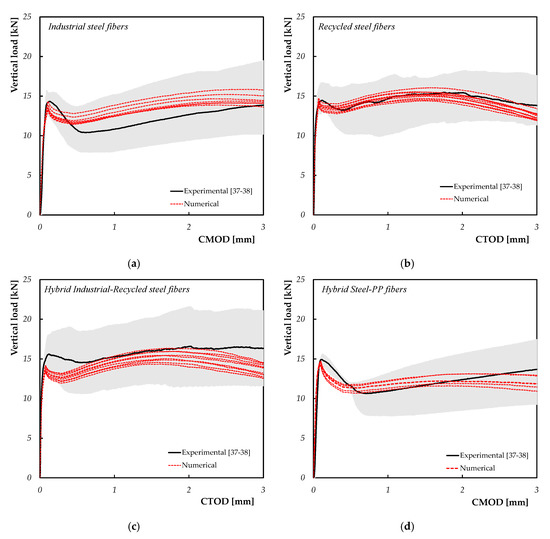
Figure 7.
Representative numerical versus experimental data for (a) ISF-FRC, (b) RSF-FRC, (c) Hybrid ISF-RSF FRC and (d) Hybrid ISF-PPF FRC mixtures.
The curves reported in Figure 7 demonstrate that the numerical simulations are able to reproduce the experimental results in a satisfactory manner. This evidence is clearer when ISF and/or PPF fibers are employed, while some scatter is registered for the Hybrid ISF-RSF FRC mixtures. This can be attributed to the fact that the ISF and PPF are industrial products meanwhile the RSF are derived by processing the waste of end-of-life tires. For these reasons, the RSF fibers (being a recycled product) present variable geometric characteristic but, in the present model only the average values (in terms of fibers’ diameter and length) are considered.
A more comprehensive comparison between the experimental and numerical analysis is performed in terms of work capacity and ductility indices (Figure 8). The points plotted in Figure 8 represent the average values of 1000 performed simulations for each type of mixture.
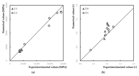
Figure 8.
Numerical versus experimental data for (a) work capacity indices and (b) ductility indices.
In terms of work capacity indices (U1 and U2), it is possible to note (Figure 8a) how the model is able to simulate the behavior obtained from the experimental tests. As a matter of the fact, the RSF-FRC mixtures present results almost coincident both in terms of U1 (8.23 Nm for the numerical model versus 8.25 Nm obtained in the experimental tests) and of U2 (34.49 Nm in the numerical analysis and 35.40 Nm in the case of experimental data). Similar results are also obtained in the other cases, especially for the ISF-FRC mixtures.
On the other hand, as a general trend the numerical simulations tend to overestimate (of around 20–25%) the D0 experimental values (Figure 8a). This difference is attributable to the underestimation of the first crack resistance flf (see for example Figure 7c), as D0 is strictly related to the latter. Conversely, the simulated ductility index D1 are closer to the corresponding experimental results (Figure 8b) and the scatter is often lower than 1–2%.
5. Conclusions
This paper presented a numerical model aimed at simulating the post-cracking response of FRCCs notched beams subjected to flexural loads. The cracked-hinge meso-mechanical model presented herein was also validated by comparing the results of experimental data already available in the literature. The following conclusions can be noted:
- -
- The obtained results show that the cracked-hinge model is able to represent quite faithfully the post-cracking behavior of the fiber-reinforced composites. Particularly, it has been shown that the load-COD curves (both in terms of CTOD and CMOD) are actually very close to the average experimental trend, especially for the mixtures reinforced with only industrial steel fibers.
- -
- For the hybrid mixtures, however, the results are certainly more than satisfactory, but could be further improved by further developing the model with the aim to take into account explicitly of the individual variation of geometric properties for recycled fibers.
- -
- The capability of the model to simulate the post-cracking behavior is clearly demonstrated. Further, the model is capable to reproduce the contribution of different types of fibers (either straight or hooked, made of steel or propylene) and this is a specific advantage of the proposed meso-mechanical approach;
- -
- The agreement obtained in terms of load-CMOD/CTOD curves is then reflected also in the characteristic parameters of the post-cracking behavior of the material. In fact, the values found are close to the experimental values in terms of work capacity and ductility indices.
Further evolutions of the present model are currently under development with the aim to generalise the theory presented in this study to fibers characterized by more complex features, such as embossments, curved profiles, or fractal geometries [39]. Such fibers may be 3D-printed in polymeric and metallic materials, so as to generate optimized fiber geometries and matrix–fiber fractal interlocking effects [40,41,42].
Author Contributions
Conceptualization, E.M. and M.P.; methodology, E.M., M.P., and F.F.; software, E.M.; validation, E.M. and M.P; formal analysis, E.M., M.P., and F.F.; investigation, M.P.; data curation, M.P.; writing—original draft preparation, M.P.; writing—review and editing, E.M. and F.F.; visualization, E.M., M.P., and F.F.; supervision, E.M. and F.F.; project administration, E.M. All authors have read and agreed to the published version of the manuscript.
Funding
This study is part of the Research Project SUPERCONCRETE (H2020-MSCA-RISE-2014, n. 645704) granted by the EU whose financial support is gratefully acknowledged.
Acknowledgments
The Author wishes to acknowledge the contribution of Agostino De Santis who ran some of the numerical analyses as part of his M.Sc. Thesis in Civil Engineering at the University of Salerno.
Conflicts of Interest
The authors declare no conflict of interest.
References
- Yoo, D.Y.; Banthia, N. Mechanical properties of ultra-high-performance fiber-reinforced concrete: A review. Cem. Concr. Compos. 2016, 73, 267–280. [Google Scholar] [CrossRef]
- Grabois, T.M.; Cordeiro, G.C.; Toledo Filho, R.D. Fresh and hardened-state properties of self-compacting lightweight concrete reinforced with steel fibers. Constr. Build. Mater. 2016, 104, 284–292. [Google Scholar] [CrossRef]
- da Silva, M.A.; Pepe, M.; de Andrade, R.G.M.; Pfeil, M.S.; Toledo Filho, R.D. Rheological and mechanical behavior of high strength steel fiber-river gravel self compacting concrete. Constr. Build. Mater. 2017, 150, 606–618. [Google Scholar] [CrossRef]
- Torres, J.A.; Lantsoght, E.O. Influence of Fiber Content on Shear Capacity of Steel Fiber-Reinforced Concrete Beams. Fibers 2019, 7, 102. [Google Scholar] [CrossRef]
- Karimi, M.M.; Darabi, M.K.; Jahanbakhsh, H.; Jahangiri, B.; Rushing, J.F. Effect of steel wool fibers on mechanical and induction heating response of conductive asphalt concrete. Int. J. Pavement Eng. 2019, 1–14. [Google Scholar] [CrossRef]
- Zhu, H.; Zhang, D.; Wang, T.; Wu, H.; Li, V.C. Mechanical and self-healing behavior of low carbon engineered cementitious composites reinforced with PP-fibers. Constr. Build. Mater. 2020, 259, 119805. [Google Scholar] [CrossRef]
- Ardanuy, M.; Claramunt, J.; Toledo Filho, R.D. Cellulosic fiber reinforced cement-based composites: A review of recent research. Constr. Build. Mater. 2015, 79, 115–128. [Google Scholar] [CrossRef]
- Ferrara, G.; Pepe, M.; Martinelli, E.; Tolêdo Filho, R.D. Influence of an impregnation treatment on the morphology and mechanical behaviour of flax yarns embedded in hydraulic lime mortar. Fibers 2019, 7, 30. [Google Scholar] [CrossRef]
- Martinelli, E.; Caggiano, A.; Xargay, H. An experimental study on the post-cracking behaviour of Hybrid Industrial/Recycled Steel Fibre-Reinforced Concrete. Constr. Build. Mater. 2015, 94, 290–298. [Google Scholar] [CrossRef]
- Spadea, S.; Farina, I.; Carrafiello, A.; Fraternali, F. Recycled nylon fibers as cement mortar reinforcement. Constr. Build. Mater. 2015, 80, 200–209. [Google Scholar] [CrossRef]
- Frazão, C.M.V.; Barros, J.A.O.; Bogas, J.A. Durability of Recycled Steel Fiber Reinforced Concrete in Chloride Environment. Fibers 2019, 7, 111. [Google Scholar] [CrossRef]
- Banthia, N.; Sappakittipakorn, M. Toughness enhancement in steel fiber reinforced concrete through fiber hybridization. Cem. Concr. Res. 2007, 37, 1366–1372. [Google Scholar] [CrossRef]
- Mobasher, B.; Yao, Y.; Soranakom, C. Analytical solutions for flexural design of hybrid steel fiber reinforced concrete beams. Eng. Struct. 2015, 100, 164–177. [Google Scholar] [CrossRef]
- Farina, I.; Fabbrocino, F.; Carpentieri, G.; Modano, M.; Amendola, A.; Goodall, R.; Fraternali, F. On the reinforcement of cement mortars through 3D printed polymeric and metallic fibers. Compos. Part B Eng. 2016, 90, 76–85. [Google Scholar] [CrossRef]
- Guerini, V.; Conforti, A.; Plizzari, G.; Kawashima, S. Influence of Steel and Macro-Synthetic Fibers on Concrete Properties. Fibers 2018, 6, 47. [Google Scholar] [CrossRef]
- Chi, Y.; Yu, M.; Huang, L.; Xu, L. Finite element modeling of steel-polypropylene hybrid fiber reinforced concrete using modified concrete damaged plasticity. Engineering Structures 2017, 148, 23–35. [Google Scholar] [CrossRef]
- Bošnjak, J.; Sharma, A.; Grauf, K. Mechanical Properties of Concrete with Steel and Polypropylene Fibres at Elevated Temperatures. Fibers 2019, 7, 9. [Google Scholar] [CrossRef]
- Othman, H.; Marzouk, H.; Sherif, M. Effects of variations in compressive strength and fibre content on dynamic properties of ultra-high performance fibre-reinforced concrete. Constr. Build. Mater. 2019, 195, 547–556. [Google Scholar] [CrossRef]
- Carvalho, M.R.; Barros, J.A.; Zhang, Y.; Dias-da-Costa, D. A computational model for simulation of steel fibre reinforced concrete with explicit fibres and cracks. Comput. Methods Appl. Mech. Eng. 2020, 363, 112879. [Google Scholar] [CrossRef]
- Farina, I.; Modano, M.; Zuccaro, G.; Goodall, R.; Colangelo, F. Improving flexural strength and toughness of geopolymer mortars through additively manufactured metallic rebars. Compos. Part B Eng. 2018, 145, 155–161. [Google Scholar] [CrossRef]
- Abed, F.; Alhafiz, A.R. Effect of basalt fibers on the flexural behavior of concrete beams reinforced with BFRP bars. Compos. Struct. 2019, 215, 23–34. [Google Scholar] [CrossRef]
- ASTM C1018-97. Standard Test Method for Flexural Toughness and First-Crack Strength of Fiber-Reinforced Concrete (Using Beam with Third-Point Loading); ASTM International: West Conshohocken, PA, USA, 1997. [Google Scholar]
- RILEM-TC-162-TDF. Test and design methods for steel fibre reinforced concrete–bending test, final recommendation. Mater. Struct. 2002, 35, 579–582. [Google Scholar] [CrossRef]
- EN 14651. Test Method for Metallic Fibred Concrete-Measuring the Flexural Tensile Strength (Limit of Proportionality (LOP), Residual); CEN: Brussels, Belgium, 2005. [Google Scholar]
- UNI 11039-1. Steel Fiber Reinforced Concrete-Definitions, Classification and Designation; UNI: Milan, Italy, 2003. [Google Scholar]
- UNI 11039-2. Steel Fiber Reinforced Concrete-Test Method to Determine the First Crack Strength and Ductility Indexes; UNI: Milan, Italy, 2003. [Google Scholar]
- Code, M. Fib Model Code for Concrete Structures 2010. Fédération Internationale du Béton; Ernst & Sohn: Berlin, Germany, 2013; p. 434. [Google Scholar]
- Hu, X.D.; Day, R.; Dux, P. Biaxial failure model for fiber reinforced concrete. J. Mater. Civ. Eng. 2003, 15, 609–615. [Google Scholar] [CrossRef]
- Li, F.; Li, Z. Continuum damage mechanics based modeling of fiber reinforced concrete in tension. Int. J. Solids Struct. 2001, 38, 777–793. [Google Scholar] [CrossRef]
- Beghini, A.; Bažant, Z.P.; Zhou, Y.; Gouirand, O.; Caner, F.C. Microplane model M5f for multiaxial behavior and fracture of fiber-reinforced concrete. J. Eng. Mech. 2007, 133, 66–75. [Google Scholar] [CrossRef]
- Ramm, E.; Hund, A.; Hettich, T. A variational multiscale model for composites with special emphasis on the X-FEM and level sets. In Computational Modelling of Concrete Structures: Proceedings of the EURO-C; CRC Press: Boca Raton, FL, USA, 2006; pp. 27–30. [Google Scholar]
- Caggiano, A.; Etse, G.; Martinelli, E. Zero-thickness interface model formulation for failure behavior of fiber-reinforced cementitious composites. Comput. Struct. 2012, 98, 23–32. [Google Scholar] [CrossRef]
- El-Helou, R.G.; Moen, C.D.; Lale, E.; Cusatis, G. Lattice discrete particle modeling of buckling deformation in thin ultra-high-performance fiber-reinforced concrete plates. Comput. Model. Concr. Struct. 2014, 1, 365–371. [Google Scholar] [CrossRef]
- Hillerborg, A.; Modeer, M.; Petersson, P.E. Analysis of Crack Formation and Crack Growth in Concrete by Means of Fracture Mechanics and Finite Elements. Cem. Concr. Res. 1976, 6, 773–781. [Google Scholar] [CrossRef]
- Olesen, J.F. Fictitious crack propagation in fiber-reinforced concrete beams. J. Eng. Mech. 2001, 127, 272–280. [Google Scholar] [CrossRef]
- Armelin, H.S.; Banthia, N. Predicting the flexural postcracking performance of steel fiber reinforced concrete from the pullout of single fibers. Mater. J. 1997, 94, 18–31. [Google Scholar]
- Caggiano, A.; Folino, P.; Lima, C.; Martinelli, E.; Pepe, M. On the mechanical response of hybrid fiber reinforced concrete with recycled and industrial steel fibers. Constr. Build. Mater. 2017, 147, 286–295. [CrossRef]
- Caggiano, A.; Gambarelli, S.; Martinelli, E.; Nisticò, N.; Pepe, M. Experimental characterization of the post-cracking response in hybrid steel/polypropylene fiber-reinforced concrete. Constr. Build. Mater. 2016, 125, 1035–1043. [Google Scholar] [CrossRef]
- Farina, I.; Goodall, R.; Hernández-Nava, E.; di Filippo, A.; Colangelo, F.; Fraternali, F. Design, microstructure and mechanical characterization of Ti6Al4V reinforcing elements for cement composites with fractal architecture. Mater. Des. 2019, 172, 107758. [Google Scholar] [CrossRef]
- Khoshhesab, M.M.; Li, Y. Mechanical behavior of 3D printed biomimetic koch fractal contact and interlocking. Extreme Mech. Lett. 2018, 24, 58–65. [Google Scholar] [CrossRef]
- Li, Y.; Ortiz, C.; Boyce, M.C. A generalized mechanical model for suture inter-faces of arbitrary geometry. J. Mech. Phys. Solids 2013, 61, 1144–1167. [Google Scholar] [CrossRef]
- Farina, I.; Fabbrocino, F.; Colangelo, F.; Feo, L.; Fraternali, F. Surface roughness effects on the reinforcement of cement mortars through 3D printed metallic fibers. Compos. Part B Eng. 2016, 99, 305–311. [Google Scholar] [CrossRef]


© 2020 by the authors. Licensee MDPI, Basel, Switzerland. This article is an open access article distributed under the terms and conditions of the Creative Commons Attribution (CC BY) license (http://creativecommons.org/licenses/by/4.0/).