Article

Stabilization and Incipient Carbonization of Electrospun Polyacrylonitrile Nanofibers Fixated on Aluminum Substrates

1
Faculty of Engineering and Mathematics, Bielefeld University of Applied Sciences, Interaktion 1, 33619 Bielefeld, Germany
2
Faculty of Physics, Bielefeld University, Universitätsstraße 25, 33615 Bielefeld, Germany
*
Author to whom correspondence should be addressed.
Fibers 2020, 8(9), 55; https://doi.org/10.3390/fib8090055
Submission received: 8 July 2020 / Revised: 14 August 2020 / Accepted: 19 August 2020 / Published: 21 August 2020
(This article belongs to the Special Issue Carbon Based Composites for Advanced Sustainable Technologies)

Abstract

:
Polyacrylonitrile (PAN) nanofibers, prepared by electrospinning, are often used as a precursor for carbon nanofibers. The thermal carbonization process necessitates a preceding oxidative stabilization, which is usually performed thermally, i.e., by carefully heating the electrospun nanofibers in an oven. One of the typical problems occurring during this process is a strong deformation of the fiber morphologies—the fibers become thicker and shorter, and show partly undesired conglutinations. This problem can be solved by stretching the nanofiber mat during thermal treatment, which, on the other hand, can lead to breakage of the nanofiber mat. In a previous study, we have shown that the electrospinning of PAN on aluminum foils and the subsequent stabilization of this substrate is a simple method for retaining the fiber morphology without breaking the nanofiber mat. Here, we report on the impact of different aluminum foils on the physical and chemical properties of stabilized PAN nanofibers mats, and on the following incipient carbonization process at a temperature of max. 600 °C, i.e., below the melting temperature of aluminum.

1. Introduction

Polyacrylonitrile (PAN) is a common precursor for carbon, using macroscopic fibers or electrospun nanofibers [1,2]. Carbon nanofibers are typically used in composites due to their mechanical properties [3], but also as electrode material in energy storage devices [4] or super-capacitors [5] due to their electrical conductivity and high specific surface area. PAN can be electrospun from a polymer solution by the widely used needle-based technique or by diverse needle-less methods, such as drum- or wire-based electrospinning. Besides the relatively high carbon yield of PAN [6], this polymer can be electrospun from the low-toxic solvent dimethyl sulfoxide (DMSO) [7] with a significantly higher fiber yield and better homogeneity than other polymers [8]. It is therefore suitable for medical applications wherein residues of toxic solvents might impede the patients’ health, and is less harmful to the environment than other synthetic polymers.
Before high-temperature carbonization, usually from 500 °C upwards, a stabilization step is necessary to preclude thermal decomposition. During thermal stabilization in air, different chemical processes occur, such as oxidation, cyclization, crosslinking, aromatization and dehydrogenation [9,10]. These processes are influenced by the process parameters, especially the heating rate, the final temperature and the time of the isothermal treatment [11,12,13,14].
While these influences are often discussed in detail in the literature, the problem of undesired modifications of the fiber’s morphology is scarcely mentioned. The fiber deformation upon thermal stabilization results from the heat-induced relief of internal tension introduced into the fibers during the electrospinning process due to extreme stretching of the polymers [15]. While the formation of conglutinations at the contact points is sometimes unproblematic [16,17] and can often be avoided by carefully tailoring the stabilization parameters [18], a larger problem is posed by the typical shrinking and bending of unfixed fibers during stabilization. Several approaches are reported in the literature, such as the stretching of bundles of nanofibers mats with a weight [19,20,21] or the fixing of nanofiber mats at two opposite sides [22,23], or even at all four sides [14,24]. Especially the latter was shown to lead to breaking of the nanofiber mats.
In a previous study, we demonstrated that a simple method for overcoming these problems involves electrospinning on aluminum foils as substrates, and stabilizing the whole composite. In this way, the forces that would otherwise cause the nanofiber mats to break are distributed over the entire surface, making stabilization possible without fiber deformation [25]. Here, we report on further experiments, using different aluminum foils and varying the process parameters of stabilization and incipient carbonization at 500 °C and 600 °C, i.e., well below the melting temperature of aluminum, to optimize both processes.

2. Materials and Methods

The needle-less electrospinning machine “Nanospider Lab” (Elmarco, Liberec, Czech Republic) was applied to prepare PAN nanofiber mats, using the following spinning parameters: voltage 80 kV, electrode–substrate distance 240 mm, nozzle diameter 0.9 mm, carriage speed 100 mm/s, substrate speed 0 mm/min, relative humidity and temperature in the spinning chamber 33% and 22 °C, respectively, and spinning duration 30 min. These process parameters were optimized in diverse previous studies.
The spinning solution was prepared from 16 wt.% PAN (copolymer with 6% methyl methacrylate, X-PAN, Dralon, Dormagen, Germany) dissolved in DMSO (≥99.9%, S3 chemicals, Bad Oeynhausen, Germany) by stirring for 2 h at room temperature. This spinning solution contains enough polymer to avoid bead formation, while it is still has low enough viscosity to be electrospun with a sufficient nanofiber gain [26].
Aluminum foils with three different thicknesses (2 µm (Rewe, Köln, Germany); 12 µm (Superb Home, Poland); 35 µm (Vireo.de, Merseburg, Germany)) were glued onto the polypropylene nonwoven (Elmarco) commonly used as substrate with the dull side on top, unless otherwise indicated. The nanofiber mats were not separated from these aluminum foils after electrospinning.
Stabilization was carried out in a muffle oven B150 (Nabertherm, Lilienthal, Germany) by applying a heat rate of 1 °C/min (or different, if mentioned in the text) from room temperature to 280 °C whereby the sample was treated isothermally for 1 h (or longer, if mentioned) in air. For the subsequent incipient carbonization, a furnace CTF 12/TZF 12 (Carbolite Gero Ltd., Hope, UK) was used, heating the samples at a rate of 10 °C/min to 500 °C (or 600 °C) whereby they were isothermally treated for 1 h and steadily exposed to a nitrogen flow of 180 mL/min. While a temperature of 500 °C can be regarded as enabling incipient carbonization, possibly more clearly showing the residual differences of the stabilization process, a temperature of 600 °C will lead to a higher degree of carbonization, while still staying below the melting temperature of the aluminum substrates.
Examinations were performed using a camera Canon 1300D with Tamron SP AF 17–50 mm F/2.8 XR Di II LD aspherical lens and a Fourier-transform infrared (FTIR) spectroscope Excalibur 3100 (Varian Inc., Palo Alto, CA, USA). For FTIR in attenuated total reflection mode (ATR-FTIR), the samples were pressed onto a diamond ATR crystal, which results in a penetration depth of about 1.7µm, depending on angle and wavenumber. The spectra cover a frequency range from 4000 to 700 cm−1. Each spectrum was averaged over 32 scans and corrected for atmospheric noise.
Further microscopic investigations were performed with the helium ion microscope (HIM) Orion Plus (Carl Zeiss, Jena, Germany) applying an acceleration voltage of 36 kV. The spot control was set to 5.8 to obtain a beam current of 0.3–0.5 PA. In contrast to a scanning electron microscope (SEM), HIM allows non-conductive surfaces to be imaged even without a conductive coating. To avoid charging effects during secondary electron detection, an electron flood gun was used after each line scan with a flood energy of 500 eV and a flood time of 50 µs.
Colorimetry was performed with the spectrophotometer ColorLite sph900 (ColorLite, Katlenburg-Lindau, Germany). The color difference values ΔE*ab (Euclidean distance of the L*a*b* values) based on the Commission Internationale de l’Eclairage (CIE) colorimetric system were measured with a 45°/0° probe using standard light D65 and a 10° observation angle. All color difference values have been determined relative to a standard white sample MA38 BAM-Standard (defined by Federal Institute for Materials Research and Testing, Berlin, Germany, purchased from ColorLite) 1E2187c.

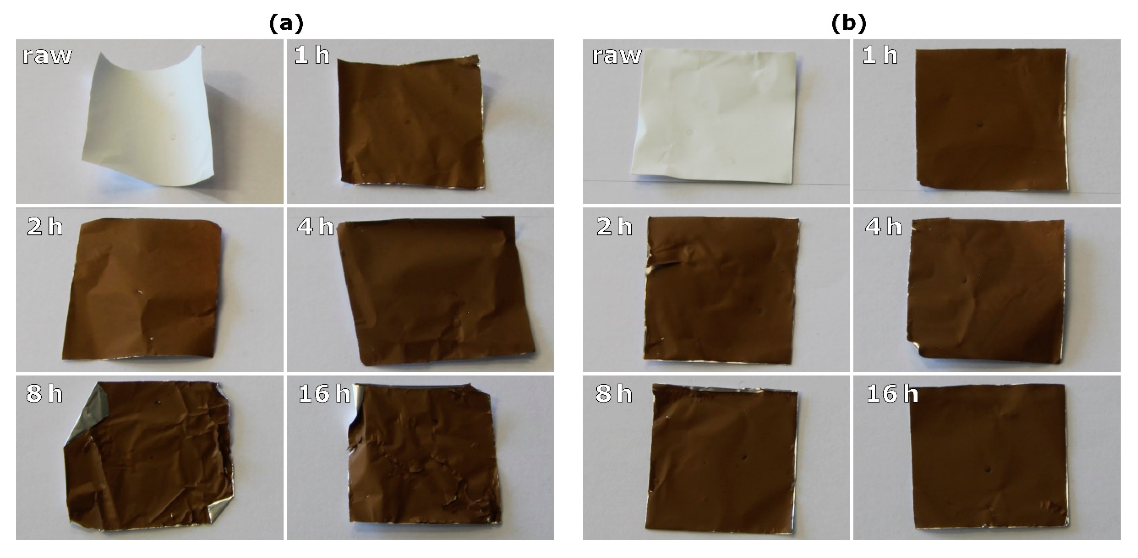
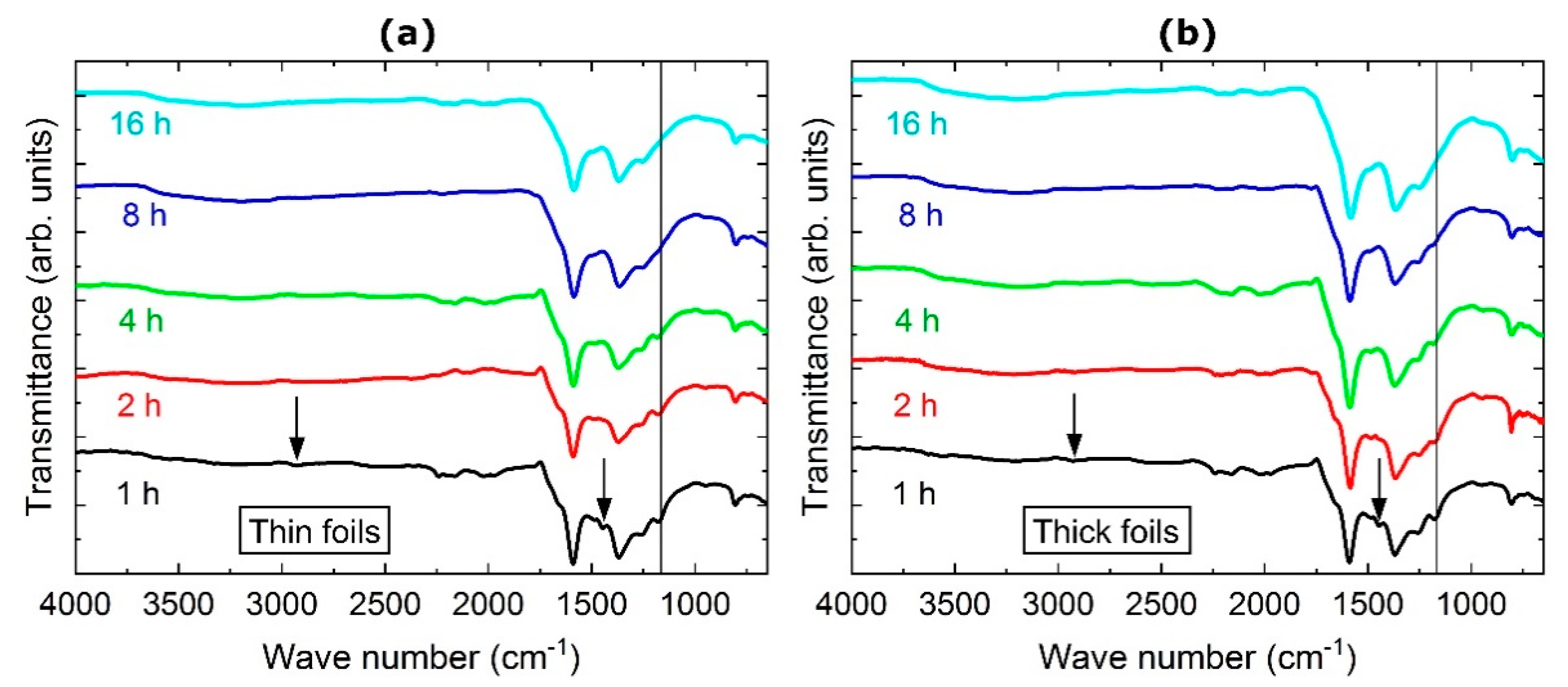
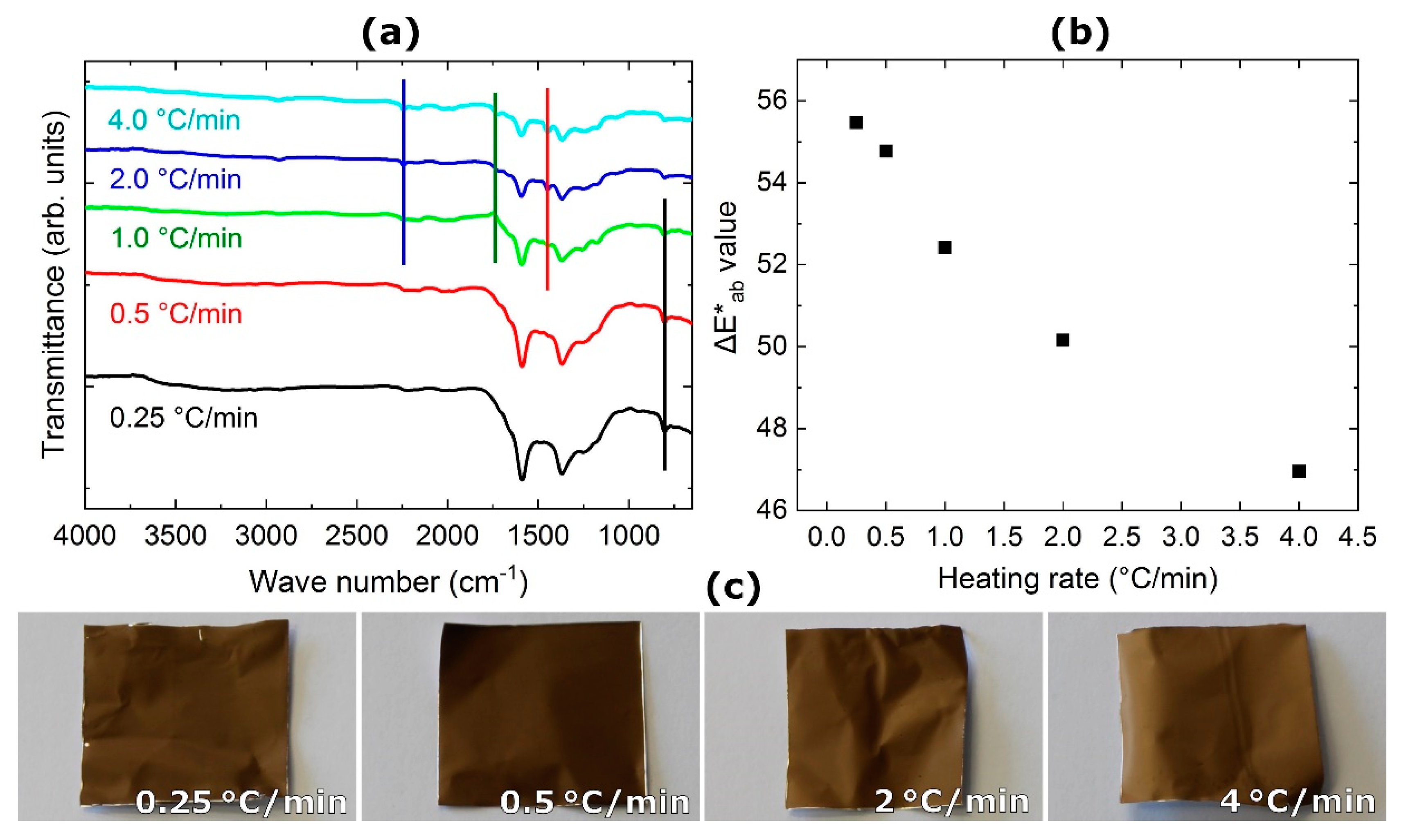
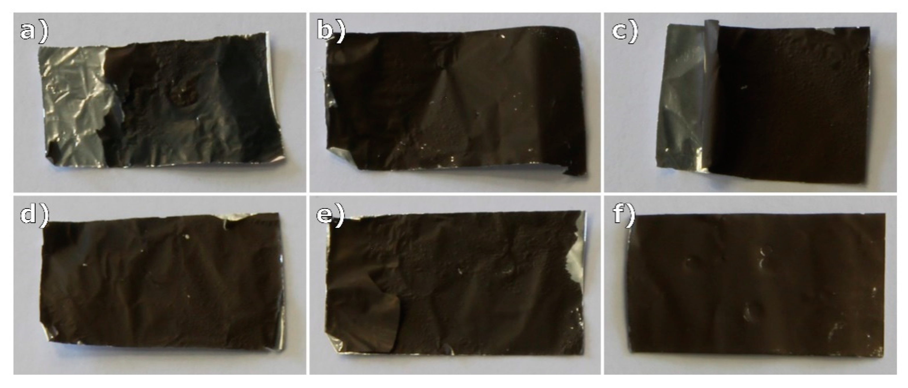
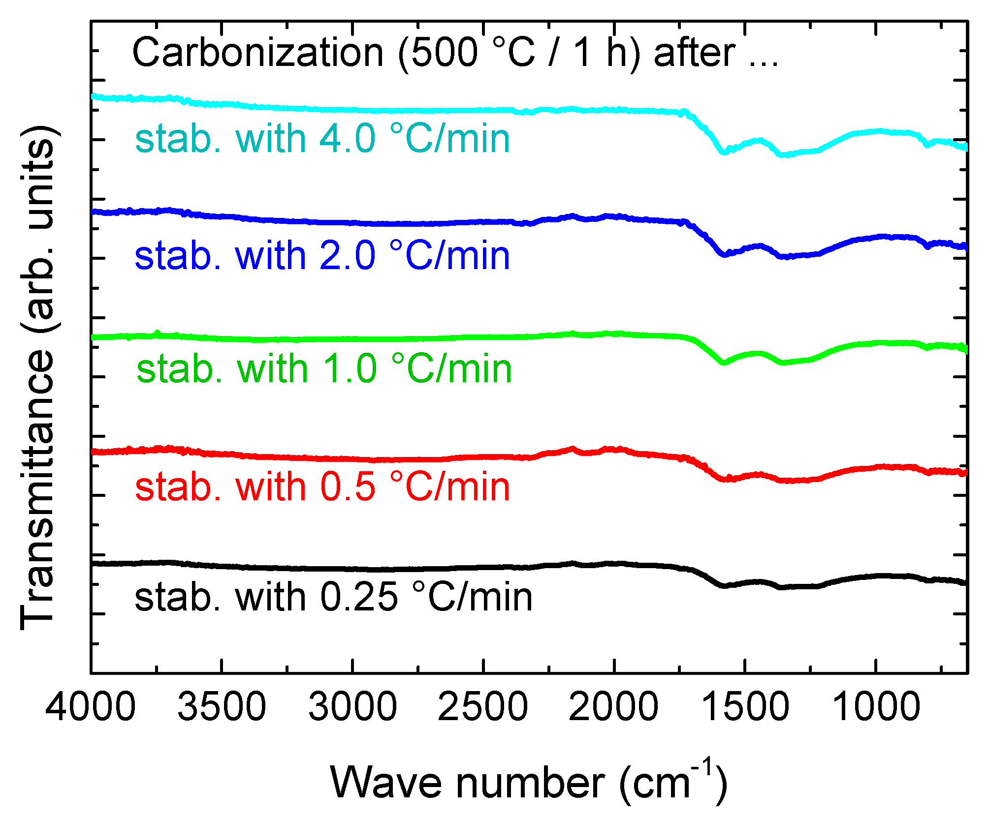
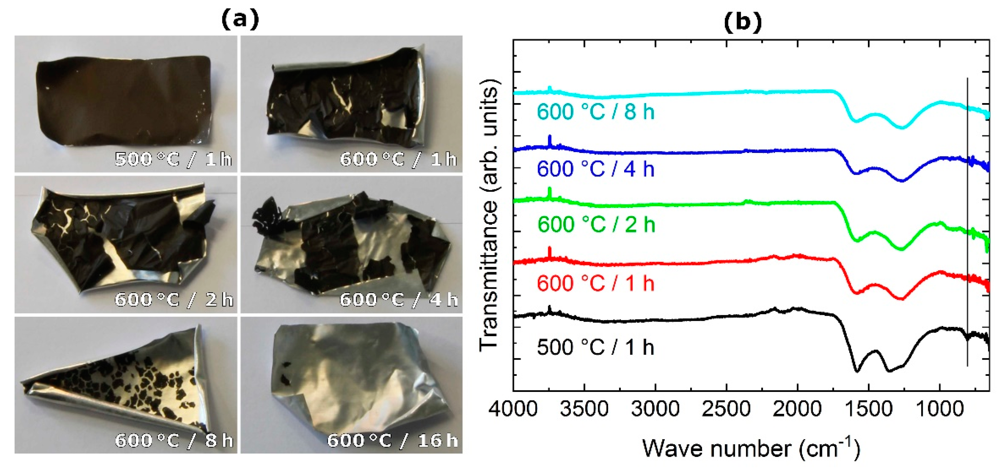
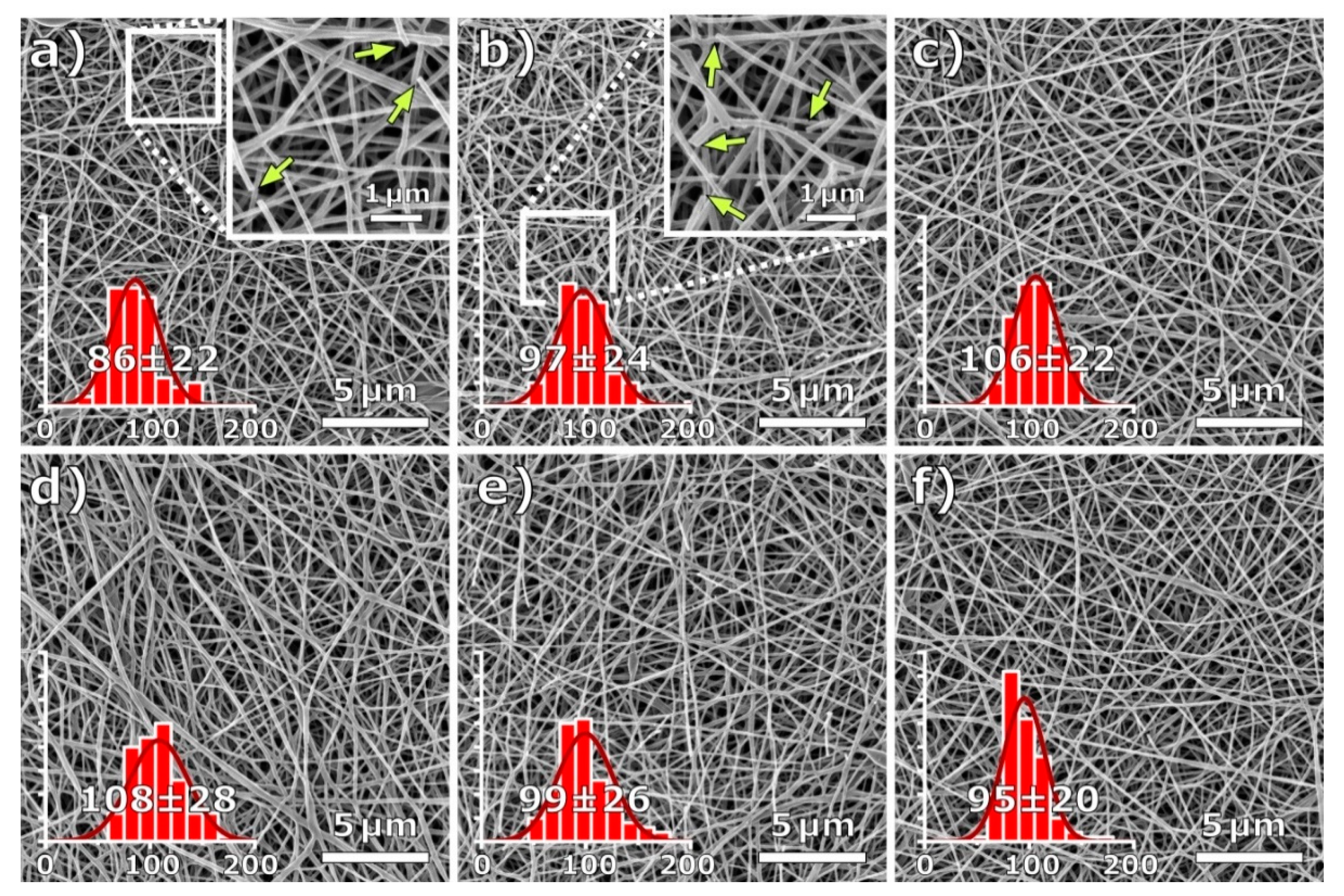
3. Results and Discussion

Figure 1 depicts photographs of samples after different stabilization times, prepared on both thin (Figure 1a) and thick aluminum foil (Figure 1b). While a clear color difference between the shortest and the longest stabilization durations is visible, the color change between directly adjacent stabilization times is hard to quantify.
To evaluate the influence of the stabilization duration in more detail, Figure 2 depicts FTIR spectra of the samples shown in Figure 1. At first glance, no large differences between the curves are visible. In all cases, the spectra contain two characteristic peaks, as expected after stabilization: the large double-peak of C = N stretching vibrations at 1582 cm−1 or C = C stretching vibration at 1660cm−1 [13], and the second large peak around 1360 cm−1 due to C−H bending and C−H2 wagging vibration [27]. The smaller peak around 800 cm−1 can be attributed to aromatic C−H vibrations, originating from oxidative dehydrogenation aromatization [28].
Figure 2 shows, nevertheless, differences as well. For 1 h stabilization time, peaks at 2938 cm−1 and 1380 cm−1 (black arrows) are still visible, which can be attributed to the bending and stretching vibrations of C−H2 [13]. These peaks are vanished for the 2 h stabilization duration, indicating a higher degree of stabilization with less H2 left in the fibers. The peak at 1161 cm−1 (black lines), corresponding to C−N stretching vibrations [29], is still noticeable after 4 h of the isothermal stabilization phase, and vanishes only after 8 h. This comparison shows that it is not easy to define a stabilization duration after which the process is completed; the necessary stabilization duration should rather be defined according to the requirements of the respective application.
Next, the heating rates during stabilization were modified. Figure 3 shows the results derived using the thick aluminum foil, which was chosen for further experiments since it showed significantly reduced crinkling and other deformations.
Figure 3a shows FTIR spectra of samples stabilized with different heating rates up to 280 °C. It should be mentioned that the curve detected for a heating rate of 1 °C/min is identical to the curve for 1 h stabilization duration in Figure 2b. Here, the differences between the heating rates are more pronounced than the differences between the isothermal treatment durations, shown in Figure 2. This indicates that the heating rate has a larger influence on the stabilization result than the duration of the isothermal phase. As seen in Figure 3b, the measured color difference values ΔE*ab between the standard white reference and the fiber mats, as seen in Figure 3c, show a clear tendency towards lighter shades with increased heating rates, indicating an incomplete chemical transition during fast stabilization.
Comparing the curves in more detail, the small peak at 800 cm−1 (black line in Figure 3a) due to aromatic C−H vibrations, being a sign of oxidative dehydrogenation aromatization [28], decreases with increasing heating rates. On the other hand, typical PAN peaks, such as C ≡ N stretching vibrations at 2240 cm−1 (blue line), C = O stretching vibrations at 1732 cm−1 (green line) or C−H2 stretching vibrations at 1452 cm−1 (red line), remain visible, indicating incomplete stabilization [13]. Apparently, the heating rates strongly influence the result of the stabilization process, unexpectedly much more than the duration of the isothermal treatment at the maximum temperature.
Next, the stabilized samples were carbonized. An overview of parts of the nanofiber mats after incipient carbonization at 500 °C, following commonly applied stabilization parameters (1 h at 280 °C after heating with 1 °C/min), is shown in Figure 4. On the one side, it is clearly visible that the aluminum substrates are partly folded and wrinkled, and some parts of the nanofiber mats have been scratched off the aluminum foils. As the chemical structure only depends on the stabilization and carbonization process, the chemical investigation by FTIR did not reveal any differences between the six samples (not shown here); neither in terms of the foil thickness nor in terms of spinning on the shiny or the dull side.
To investigate the influence of the stabilization parameters on the final carbonization result, further tests were performed, based on the previous variation of stabilization parameters. Since the stabilization duration had almost no impact on the resulting chemical composition of the corresponding samples, here we focused on carbonizing samples previously stabilized with different heating rates. Carbonization was carried out at 500 °C for 1 h to avoid the strong crinkling and rolling of the foils, which occurs during carbonization at 600 °C. The FTIR spectra of the resulting fiber mats are shown in Figure 5.
As expected, the residual broad double peak around 1500 cm−1, stemming from stabilization, is more pronounced in the spectra of samples stabilized at increased heating rates, which were less efficiently stabilized before. These differences, however, are small; for carbonization at higher temperatures, the differences have to be investigated in order to evaluate whether slow stabilization is indeed favorable, taking into account not only the higher carbonization degree, but also the necessary larger energy consumption.
Furthermore, the carbonization was compared for temperatures of 500 °C, as before, and 600 °C, the latter being applied for different durations. Photographs and FTIR spectra are depicted in Figure 6.
In all cases, the previous stabilization cycle was carried out under the aforementioned standard conditions, and the final carbonization temperature was approached at a heating rate of 10 °C/min. It is clearly visible that even the thick aluminum foil is creased and wrinkled much more noticeably at 600 °C than at 500 °C (cf. Figure 4). This is probably due to the fact that 600 °C is only 60 °C below the melting point of aluminum, and thus causes the foil to deform. The longer the carbonization time, the more the nanofiber mat detaches from the aluminum surface.
The reason for this is probably that adhesive bonds, due to secondary valence forces, decrease with progressing aromatization due to the increasing degradation of the polar, oxygen-containing polymer ingredients. This reduction of possible bonding sites in the nanofiber mat leads to reduced bonding between the nanofiber mats and the aluminum surface. In addition, it is known from previous experiments that the nanofiber mats tend to shrinking during carbonization, which supports the detachment. This finding encourages future tests of carbonization after detaching the stabilized nanofiber mat from the substrate, to investigate whether this negative effect of longer carbonization durations is based on deformations of the substrate or can also be found for the carbonization of the free nanofiber mat. As demonstrated by Wortmann et al., most of the morphological changes occur during stabilization, whereas only minor changes occur during subsequent carbonization [15]. In addition, different metal substrates with higher melting points should be investigated. Alternatively, carbonization at higher temperatures could possibly be used to create metal/carbon composites [30].
The FTIR spectra in Figure 6b show a clear difference between incipient carbonization at 500 °C and that at 600 °C, especially as regards the peak at 800 cm−1 (black line), stemming from aromatic C−H vibrations typical for the ladder-structure resulting from the stabilization of PAN [28]. This peak is still visible after thermal treatment at 500 °C, and vanishes after carbonization at 600 °C, indicating that the higher temperature, although still far below typical carbonization temperatures of 800 °C minimum, already increases the amount of carbon in the treated nanofiber mats. The duration of the isothermal treatment, however, does not show any difference in terms of the chemical composition. This suggests further tests with even shorter carbonization durations.
For morphological investigations, Figure 7 shows HIM images of the nanofiber mats carbonized at 500 °C after stabilization with different heating rates (Figure 7a–e), as well as those carbonized at 600 °C (Figure 7f). Generally, all images show straight fibers without conglutinations or deformations, as could be expected due to stabilization on the aluminum substrate [25]. Nevertheless, some fractured fibers are visible, as indicated by the arrows in the magnified image sections of Figure 7a,b. This is to be expected as internal tension in the fibers cannot relax during thermal treatment. A carbonization process adapted to mechanical fixation will be developed in upcoming studies. The fiber diameter distributions, as seen in the inserted histograms, are relatively narrow, and are all in a similar range without significant differences, underlining the advantage of the aluminum substrate in its ability to equally distribute contraction forces due to internal tension, and thus to produce straight fibers with homogeneous diameters.

4. Conclusions

PAN nanofiber mats were stabilized and subsequently carbonized using aluminum foils as substrates. While a previous study revealed that the common problem of undesired changes in fiber morphology can be avoided by stabilization on the aluminum foil, here the influence of stabilization and carbonization parameters was evaluated. The aluminum’s thickness did not influence the chemical properties after stabilization, but the thicker foils showed strongly reduced crinkling and other undesired deformations after thermal treatment. Neither the side of the aluminum foil (shiny or dull) nor the duration of the isothermal treatment influenced the chemical properties of the stabilized samples, which were, however, significantly modified by the heating rates during stabilization. These differences were still noticeable after carbonization. Carbonization duration again did not reveal significant differences; neither did the substrate thickness during carbonization. In all cases, incipient carbonization at 500 °C revealed straight nanofibers without conglutinations.
Our results demonstrate the importance of the heating rate used for stabilization on the aluminum substrate, which impeded undesired morphological changes or conglutinations. It has also been shown that the adhesive bond between fiber mats and aluminum dissolves as carbonization progresses, which is not a significant problem, as most of the morphological changes occur during stabilization. In order to utilize the fixing effect of the substrate, the fiber mats could be completely carbonized at high temperatures after the removal of the substrate. The best results were obtained with the thickest aluminum foil, with a heating rate during stabilization of 0.25–0.5 °C/min and an isothermal treatment time of 1 h.

5. Patents

This study is mainly based on the patent DE 10 2018 116 009 A1 [30].

Author Contributions

Conceptualization, J.L.S. and T.G.; methodology, J.L.S., T.G., and A.E.; validation, J.L.S., T.G., M.W. and A.E.; formal analysis, J.L.S., T.G., M.W. and A.E.; investigation, J.L.S., T.G., K.T., E.D., D.W., B.B., N.F. and M.W.; writing—original draft preparation, A.E. and M.W.; writing—review and editing. All authors; visualization, J.L.S., T.G., M.W. and A.E. All authors have read and agreed to the published version of the manuscript.

Funding

This research was funded by the German Federal Ministry for Economic Affairs and Energy, grant number 03THW09K08, and by the German Federal Ministry of Education and Research, funding program Forschung an Fachhochschulen, grant number 13FH018AN9.

Acknowledgments

We are grateful to Armin Gölzhäuser from Bielefeld University for providing the opportunity to use the helium ion microscope.

Conflicts of Interest

The authors declare no conflict of interest. The funders had no role in the design of the study; in the collection, analyses, or interpretation of data; in the writing of the manuscript, or in the decision to publish the results.

References

  1. Greiner, A.; Wendorff, J.H. Electrospinning: A fascinating method for the preparation of ultrathin fibers. Angew. Chem. Int. Ed. 2007, 46, 5670–5703. [Google Scholar] [CrossRef] [PubMed]
  2. Rahaman, M.S.A.; Ismail, A.F.; Mustafa, A. A review of heat treatment on polyacrylonitrile fiber. Polym. Degrad. Stab. 2007, 92, 1421–1432. [Google Scholar] [CrossRef] [Green Version]
  3. Manoharan, M.P.; Sharma, A.; Desai, A.V.; Haque, M.A.; Bakis, C.E.; Wang, K.W. The interfacial strength of carbon nanofiber epoxy composite using single fiber pullout experiments. Nanotechnology 2009, 20, 5. [Google Scholar] [CrossRef] [PubMed]
  4. Meligrana, G.; Ferrari, S.; Lucherini, L.; Celè, J.; Colò, F.; Brugger, J.; Ricciardi, C.; Ruffo, R.; Gerbaldi, C. Na3V2(PO4)3-Supported Electrospun Carbon Nanofiber Nonwoven Fabric as Self-Standing Na-Ion Cell Cathode. ChemElectroChem 2020, 7, 1652–1659. [Google Scholar] [CrossRef]
  5. Dirican, M.; Yanilmaz, M.; Asiri, A.M.; Zhang, X.W. Polyaniline/MnO2/porous carbon nanofiber electrodes for supercapacitors. J. Electroanal. Chem. 2020, 861, 113995. [Google Scholar] [CrossRef]
  6. Trabelsi, M.; Mamun, A.; Klöcker, M.; Sabantina, L.; Großerhode, C.; Blachowicz, T.; Ehrmann, A. Increased mechanical properties of carbon nanofiber mats for possible medical applications. Fibers 2019, 7, 98. [Google Scholar] [CrossRef] [Green Version]
  7. Grothe, T.; Wehlage, D.; Böhm, T.; Remche, A.; Ehrmann, A. Needleless Electrospinning of PAN Nanofibre Mats. Tekstilec 2017, 60, 290–295. [Google Scholar] [CrossRef]
  8. Wortmann, M.; Frese, N.; Sabantina, L.; Petkau, R.; Kinzel, F.; Gölzhäuser, A.; Moritzer, E.; Hüsgen, B.; Ehrmann, A. New Polymers for needleless electrospinning from low-toxic solvents. Nanomaterials 2019, 9, 52. [Google Scholar] [CrossRef] [Green Version]
  9. Bashir, Z. A critical review of the stabilisation of polyacrylonitrile. Carbon 1991, 29, 1081–1090. [Google Scholar] [CrossRef]
  10. Ismar, E.; Sezai Sarac, A. Oxidation of polyacrylonitrile nanofiber webs as a precursor for carbon nanofiber: Aligned and non-aligned nanofibers. Polym. Bull. 2017, 75, 485–499. [Google Scholar] [CrossRef]
  11. Fitzer, E.; Frohs, W.; Heine, M. Optimization of stabilization and carbonization treatment of PAN fibres and structural characterization of the resulting carbon fibres. Carbon 1986, 24, 387–395. [Google Scholar] [CrossRef]
  12. Mathur, R.; Bahl, O.; Mittal, J. A new approach to thermal stabilization of PAN fibres. Carbon 1992, 30, 657–663. [Google Scholar] [CrossRef]
  13. Mólnar, K.; Szolnoki, B.; Toldy, A.; Vas, L.M. Thermochemical stabilization and analysis of continuously electrospun nanofibers. J. Anal. Calorim. 2014, 117, 1123–1135. [Google Scholar] [CrossRef]
  14. Sabantina, L.; Klöcker, M.; Wortmann, M.; Rodríguez-Mirasol, J.; Cordero, T.; Moritzer, E.; Finsterbusch, K.; Ehrmann, A. Stabilization of PAN nanofiber mats obtained by needleless electrospinning using DMSO as solvent. J. Ind. Text. 2020, 50, 224–239. [Google Scholar] [CrossRef]
  15. Wortmann, M.; Frese, N.; Mamun, A.; Trabelsi, M.; Keil, W.; Büker, B.; Javed, A.; Tiemann, M.; Moritzer, E.; Ehrmann, A.; et al. Chemical and Morphological Transition of Poly(acrylonitrile)/Poly(vinylidene Fluoride) Blend Nanofibers during Oxidative Stabilization and Incipient Carbonization. Nanomaterials 2020, 10, 1210. [Google Scholar] [CrossRef]
  16. Alarifi, I.M.; Alharbi, A.; Khan, W.S.; Swindle, A.; Asmatulu, R. Thermal, Electrical and Surface Hydrophobic Properties of Electrospun Polyacrylonitrile Nanofibers for Structural Health Monitoring. Materials 2015, 8, 7017–7031. [Google Scholar] [CrossRef] [PubMed] [Green Version]
  17. Arbab, S.; Teimoury, A.; Mirbaha, H.; Adolphe, D.C.; Noroozi, B.; Nourpanah, P. Optimum stabilization processing parameters for polyacrylonitrile-based carbon nanofibers and their difference with carbon (micro) fibers. Polym. Degrad. Stab. 2017, 142, 198–208. [Google Scholar] [CrossRef]
  18. Dhakate, S.R.; Gupta, A.; Chaudhari, A.; Tawale, J.; Mathur, R.B. Morphology and thermal properties of PAN copolymer based electrospun nanofibers. Synth. Met. 2011, 161, 411–419. [Google Scholar] [CrossRef]
  19. Ma, S.; Liu, J.; Liu, Q.; Liang, J.Y.; Zhao, Y.; Fong, H. Investigation of structural conversion and size effect from stretched bundle of electrospun polyacrylonitrile copolymer nanofibers during oxidative stabilization. Mater. Des. 2016, 95, 387–397. [Google Scholar] [CrossRef]
  20. Wu, S.; Zhang, F.; Yu, Y.H.; Li, P.; Yang, X.P.; Lu, J.G.; Rye, S.K. Preparation of PAN-based carbon nanofibers by hot-stretching. Compos. Interfaces 2008, 15, 671–677. [Google Scholar] [CrossRef] [Green Version]
  21. Ma, S.; Liu, J.; Qu, M.; Wang, X.; Huang, R.; Liang, J. Effects of carbonization tension on the structural and tensile properties of continuous bundles of highly aligned electrospun carbon nanofibers. Mater. Lett. 2016, 183, 369–373. [Google Scholar] [CrossRef]
  22. Santos de Oliveira, M., Jr.; Manzolli Rodrigues, B.V.; Marcuzzo, J.S.; Guerrini, L.M.; Baldan, M.R.; Rezende, M.C. A statistical approach to evaluate the oxidative process of electrospun polyacrylonitrile ultrathin fibers. J. Appl. Polym. Sci. 2017, 134, 45458. [Google Scholar] [CrossRef]
  23. Wu, M.; Wang, Q.Y.; Li, K.; Wu, Y.Q.; Liu, H.Q. Optimization of stabilization conditions for electrospun polyacrylonitrile nanofibers. Polym. Degrad. Stab. 2012, 97, 1511–1519. [Google Scholar] [CrossRef]
  24. Sabantina, L.; Wehlage, D.; Klöcker, M.; Mamun, A.; Grothe, T.; Rodrígues Mirasol, J.; Cordero, T.; Finsterbusch, K.; Ehrmann, A. Stabilization of electrospun PAN/gelatin nanofiber mats for carbonization. J. Nanomater. 2018, 2018, 6131085. [Google Scholar] [CrossRef] [Green Version]
  25. Sabantina, L.; Rodríguez-Cano, M.Á.; Klöcker, M.; García-Mateos, F.J.; Ternero-Hidalgo, J.J.; Mamun, A.; Beermann, F.; Schwakenberg, M.; Voigt, A.-L.; Rodríguez-Mirasol, J.; et al. Fixing PAN nanofiber mats during stabilization for carbonization and creating novel metal/carbon composites. Polymers 2018, 10, 735. [Google Scholar] [CrossRef] [Green Version]
  26. Grothe, T.; Storck, J.L.; Dotter, M.; Ehrmann, A. Impact of solid content in the electrospinning solution on physical and chemical properties of polyacrylonitrile (PAN) nanofibrous mats. Tekstilec. submitted.
  27. Cipriani, E.; Zanetti, M.; Bracco, P.; Brunella, V.; Luda, M.P.; Costa, L. Crosslinking and carbonization processes in PAN films and nanofibers. Polym. Degrad. Stab. 2016, 123, 178–188. [Google Scholar] [CrossRef]
  28. Gergin, I.; Ismar, E.; Sarac, A.S. Oxidative stabilization of polyacrylonitrile nanofibers and carbon nanofibers containing graphene oxide (GO): A spectroscopic and electrochemical study. Beilstein J. Nanotechnol. 2017, 8, 1616–1628. [Google Scholar] [CrossRef] [Green Version]
  29. Huang, F.L.; Xu, Y.F.; Liao, S.Q.; Yang, D.W.; Hsieh, Y.-L.; Wei, Q.F. Preparation of amidoxime polyacrylonitrile chelating nanofibers and their application for adsorption of metal ions. Materials 2013, 6, 969–980. [Google Scholar] [CrossRef] [Green Version]
  30. Sabantina, L.; Beermann, F.; Schwakenberg, M.; Voigt, A.-L.; Klöcker, M.; Ehrmann, A. Stabilisierte Metall-Carbon-Komposite. Patent Application DE 10 2018 116 009 A1, 7 February 2018. [Google Scholar]
Figure 1. Photographs of nanofiber mats stabilized on (a) thin aluminum foil and (b) thick aluminum foil. Stabilization durations are given in the insets.
Fibers 08 00055 g001
Figure 2. FTIR spectra of nanofiber mats stabilized on (a) thin aluminum foil and (b) thick aluminum foil.
Fibers 08 00055 g002
Figure 3. (a) FTIR spectra of nanofiber mats stabilized with different heating rates approaching 280 °C and subsequent 1 h isothermal phase on thick aluminum foil. (b) Change of the dimensionless color difference value ΔE*ab and (c) photographs of the same stabilized nanofiber mats.
Fibers 08 00055 g003
Figure 4. Photograph of nanofiber mats after incipient carbonization at 500 °C: fibers on shiny sides of (a) thin, (b) middle and (c) thick aluminum foil; fibers on dull sides of (d) thin, (e) middle and (f) thick aluminum foil.
Fibers 08 00055 g004
Figure 5. FTIR spectra of carbonized nanofiber mats after stabilization at 280 °C (1 h isothermal phase), approached with different heating rates.
Fibers 08 00055 g005
Figure 6. (a) Photographs of nanofiber mats carbonized at 500 °C and 600 °C for different durations on the thick aluminum foil, durations of isothermal treatment are given in the insets; (b) FTIR spectra of nanofiber mats seen in (a).
Fibers 08 00055 g006
Figure 7. Helium ion microscope (HIM) images of nanofiber mats carbonized at 500 °C after stabilization at 280 °C (1 h isothermal phase), approached with heating rates of (a) 0.25 °C/min, (b) 0.5 °C/min, (c) 1.0 °C/min, (d) 2.0 °C/min, (e) 4.0 °C/min, and (f) carbonized at 600 °C after stabilization with a heating rate of 1.0 °C/min. Inserted fiber diameter histograms show normal distributions, mean fiber diameters and their respective standard deviations. Arrows in magnified image sections indicate fiber fractures.
Fibers 08 00055 g007

