1. Introduction
The widespread use of membrane technology is limited by the low choice of polymers for production and industrial application because of high requirements towards permeability ratios and production technologies of mechanically strong films or fibers, durability, chemical resistance, affordable price of the raw materials (polymer) and others [
1].
One of the most promising commercially available polymer materials for the membrane manufacture is poly(4-methyl-1-pentene) (PMP), a semicrystalline polymer with a glass transition temperature from 20 to 30 °C and a degree of crystallinity of 20 to 80%. PMP has a high ratio of permeability/selectivity and good mechanical properties due to its bulky side chains’ high thermal stability, compared to other membrane polymers, and excellent chemical stability [
2]. The main feature of PMP is its insolubility in aliphatic and aromatic hydrocarbons, which are usually used as polymer solvents in the temperature range from 20 to 60 °C, which makes it suitable for separating gas mixtures containing various hydrocarbons, while membranes from it can be obtained by melt technology [
3]. PMP is a medium permeable polymer, exhibiting permeability coefficients (
P) higher than the
p-values of commercial polycarbonates and polysulfone hollow fibers (HFs). PMP properties allow producing membranes, and hollow fiber membranes in particular, using non-solvent technology, which is important from the standpoint of an actual ecological approach.
HF membrane modules provide a higher specific area compared to other module types, and therefore, HF configuration is of greater commercial interest. In addition, HF membranes do not require the installation of additional supporting elements such as spacers that facilitate assembling during module production [
4]. Another advantage of HFs is that they are processable to textile modules of almost any shape. Hollow fiber gas separation membranes named “Graviton” based on PMP began to be produced back in the 1980s in Russia at NPO Chimvolokno (Moscow) [
5] but were discontinued at the end of the same century. As of today, the PMP has been most thoroughly investigated for the permeability and selectivity of the O
2/N
2 mixture for solving practical problems of obtaining technical nitrogen or concentrating oxygen; but there are also data in the literature on the permeability of other gases [
6,
7,
8]. At present, Mitsui Chemicals, Inc., Tokyo (Japan), produces membranes from PMP for blood oxygenation processes [
9].
2. Materials and Methods
Semi-crystalline PMP in pellet form was used to obtain non-porous hollow fibers. PMP is an aliphatic polyolefin with the lowest density of all thermoplastics −0.83 g/cm
3. For the melt spinning tests in this study, PMP type MX002 from Mitsui Chemicals, Inc., Tokyo (Japan) was used. This polymer grade has a glass transition temperature T
g of 21 °C and an initial crystallinity of 36% in pellet form. The high melting temperature of more than 220 °C is notably higher compared to other polyolefins, e.g., 160 °C for polypropylene. This is due to the bulky pentene side chains of PMP (see
Figure 1).
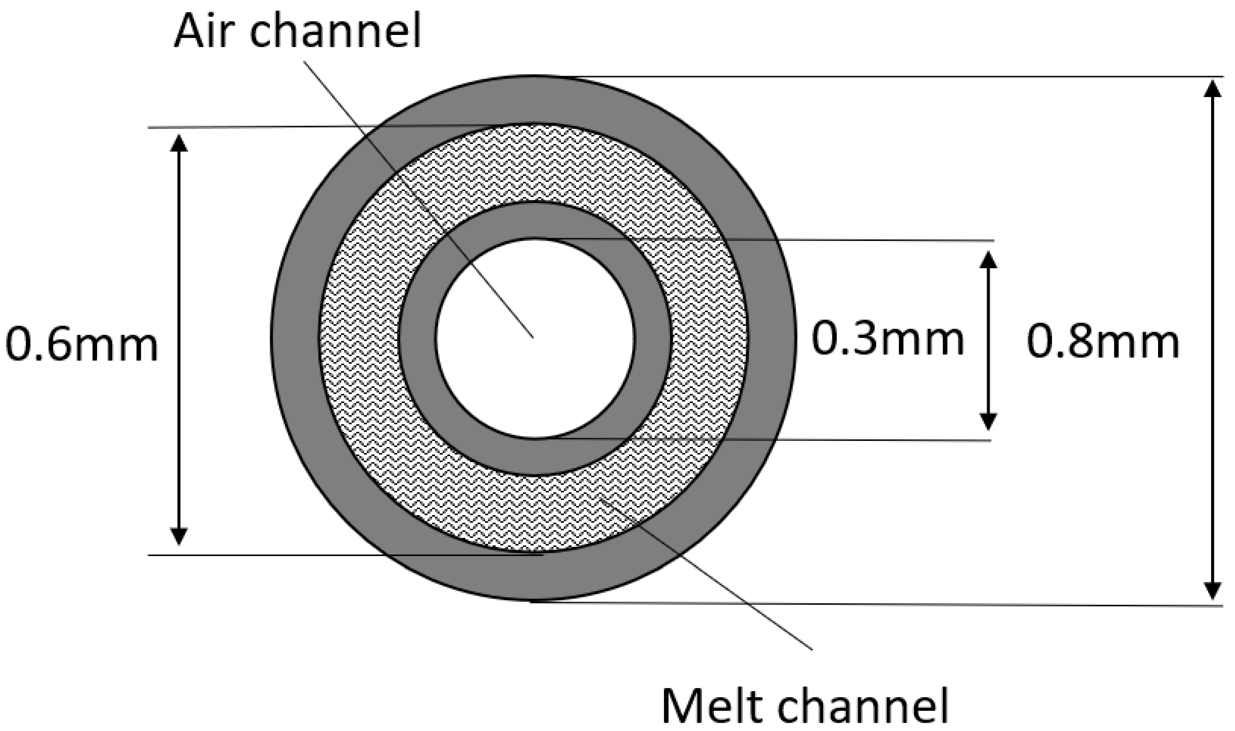
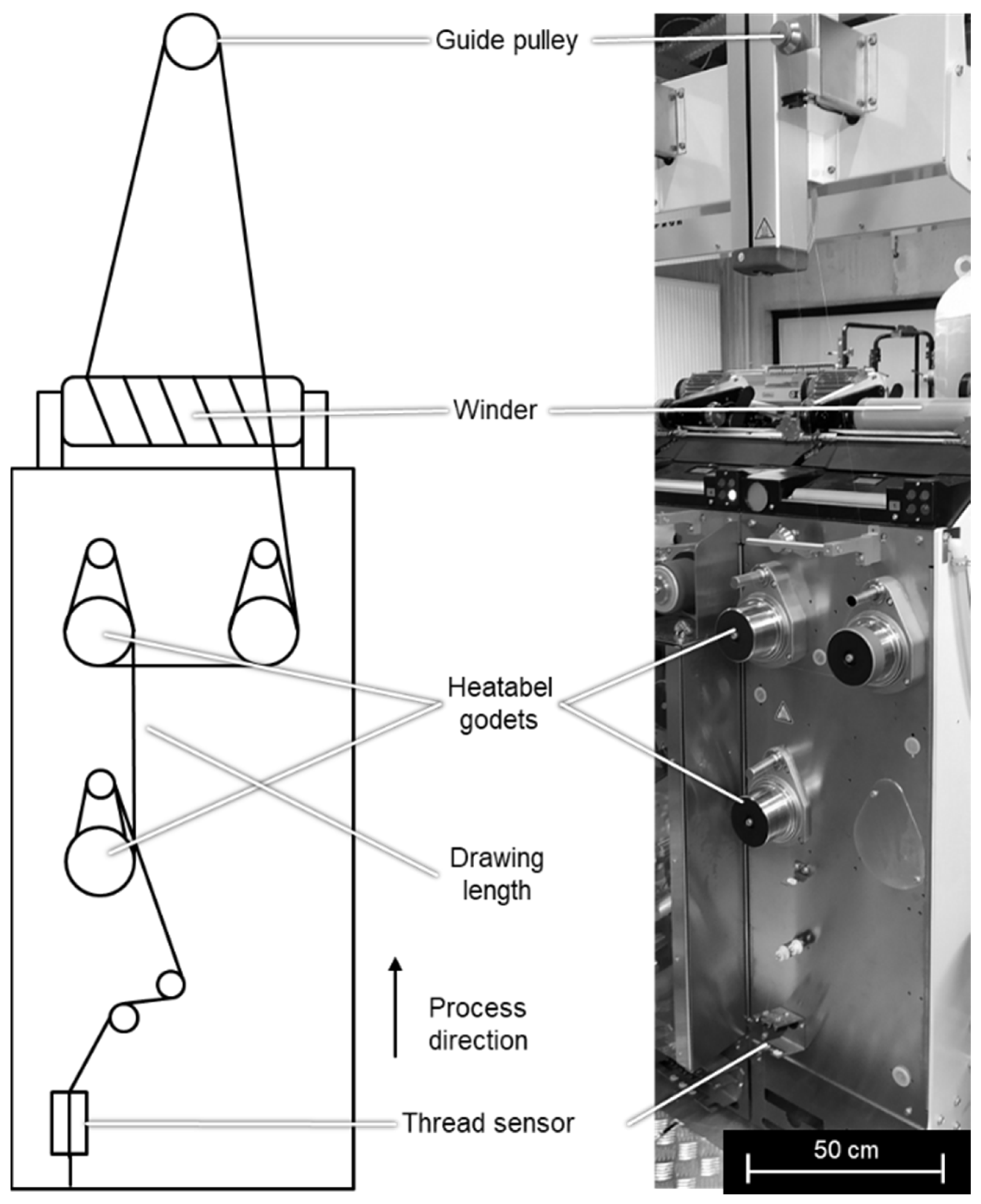
2.1. Fiber Preparation Method
Hollow fibers based on PMP pellets were melt spun using a pilot plant from Fourné Polymertechnik GmbH, Alfter (Germany) [
10]. A schematic representation of this melt spinning line is shown in
Figure 2. In the extruder, the granulate is melted due to the heat generated by the heating elements by the dissipation of mechanical energy from the extruder screw and by shear heating in the melt. The melt is fed through heated pipes to the spinning pump. The spinning pump (volumetric polymer feed 0.16 cm
3 per rotation) feeds the spinneret with a defined melt flow. The polymer melt exits the spin plate through four holes (named “shell” in
Figure 2). Each hole is separately fed with air. The air is channeled to the upper side of the spin plate and then to the center of the holes, named “core”. The die geometry is shown in
Figure 3. The so obtained four hollow fibers are formed into a bundle. Spin finish, an emulsion of oil and water, is applied to the filaments in order to obtain filament cohesion and make them textile processable.
The following setup and melt spinning parameters were used (see
Table 1).
In a subsequent step, chosen HFs are post-drawn between two heatable godets (
Figure 4). The HF yarn is passing a thread sensor and is guided to two heatable godets where the post-drawing is created. The drawing ratio is the speed of the second godet and the speed of the first godet. After drawing, the yarn is guided over another godet and a guide pulley to the winder.
To study the gas permeability of the obtained hollow fiber membranes based on PMP, laboratory membrane modules were assembled with working areas of HFs of about 60 to 80 cm
2. A photograph of the membrane module is shown in
Figure 5.
The glass transition temperature of PMP was evaluated using the DSC method, which was performed on the DSC823e unit (Mettler Toledo) using approximately 10 mg of PMP placed in an aluminum crucible. DSC thermogram was obtained from −20 to 300 °C at a heating rate of 10 °C/min in an argon atmosphere.
The cross sections of the obtained HF samples were investigated in the laboratory of the Institut für Textiltechnik of RWTH Aachen University (ITA) in Aachen (Germany) using reflected light microscopy and scanning electron microscopy (SEM) [
10]. For light microscopy, the model DM4000M from Leica, Wetzlar (Germany), was used. The maximum magnification is 1000. For the SEM, the microscope 1450 VP from Carl Zeiss AG, Oberkochen (Germany), was used with a maximum resolution of 3.5 nm using tungsten at 30 kV. The accelerating voltage is adjustable from 200 to 30 kV, and the pressure can be varied between 1 and 400 Pa.
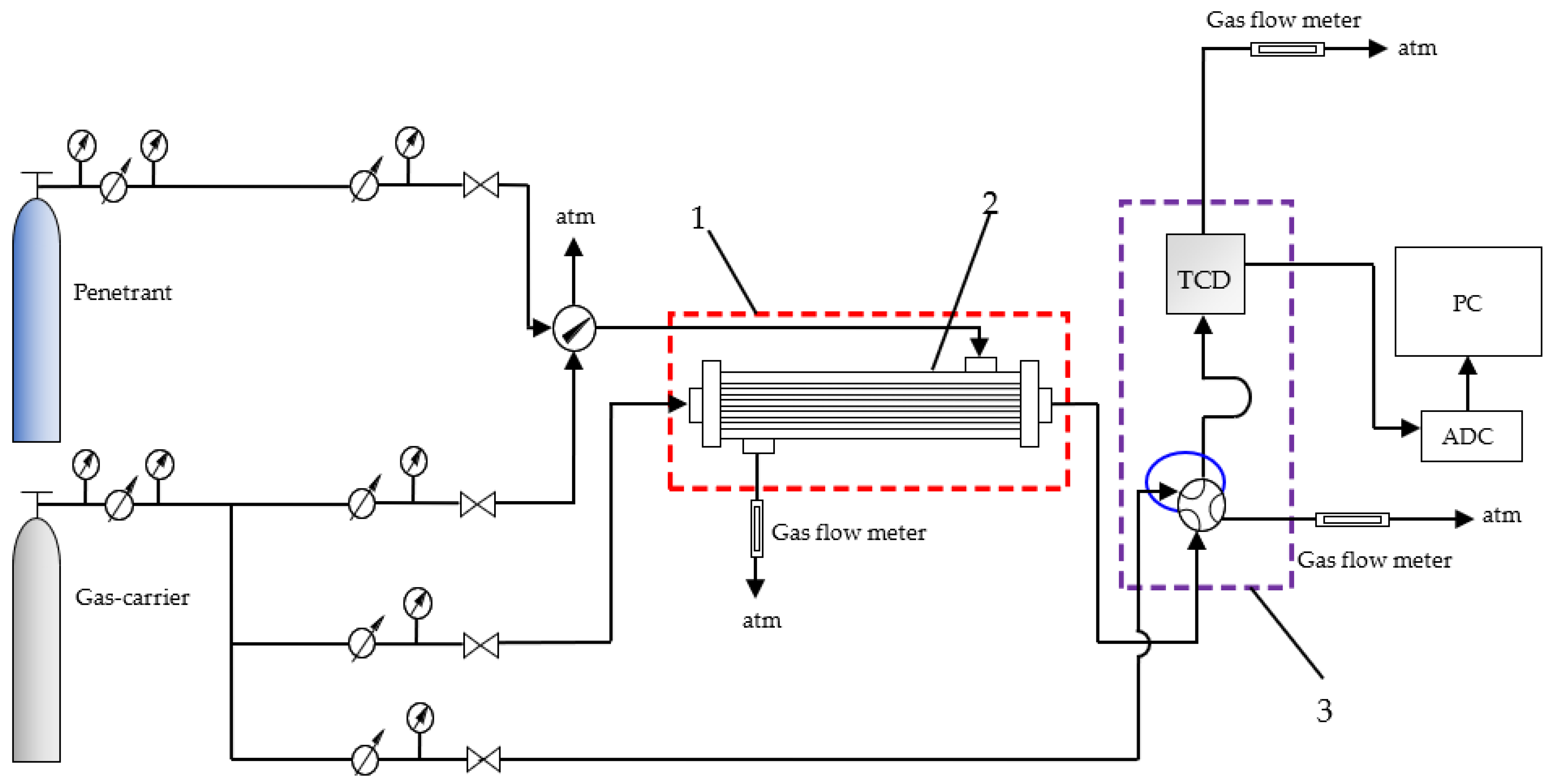
2.2. Gas Permeability Measurement Method
The permeability of CO
2, CH
4, N
2 and their mixtures was measured by the method of differential gas permeability with gas chromatographic analysis using a gas-carrier (He) at a partial pressure drop across the hollow fiber membrane around 1 atm. The setup for measuring gas permeability is shown in
Figure 6.
The test gas was fed into the shell side of the laboratory membrane module at atmospheric pressure and a flow rate of 1 cm3/s. The carrier gas was fed into the bore side of the HFs. The partial pressure drop across the HF membrane was around 1 atm. The composition of the permeate (carrier gas + penetrant) was determined by gas chromatography. Experiments were performed in a temperature range from 15 (below Tg) to 40 °C (above Tg).
The gas permeance through the HFs was calculated using the equation:
where V is the flow rate of the gas carrier with the gas studied from the bore side, m
3(STP)/s; A is a membrane area, m
2; p is the atmospheric pressure, Pa;
is the concentration of the gas studied in the gas carrier stream from the bore side, vol. %;
is the concentration of the gas studied in the shell side, vol. %.
The permeability coefficient (P) was calculated as follows:
where l is the HF wall thickness, m.
The selectivity for the pair of gases was determined by the equation:
Equation for the approximation of temperature dependence of the permeability coefficient:
where E
p is the apparent activation energy of permeability, kJ/mol; T is a temperature, K; P is the permeability coefficient, Barrer.
3. Results and Discussion
In this work, the influence of the conditions for obtaining HFs on the fiber’s geometry was investigated, and the values of gas permeability of samples of PMP HFs were obtained for various parameters of their preparation.
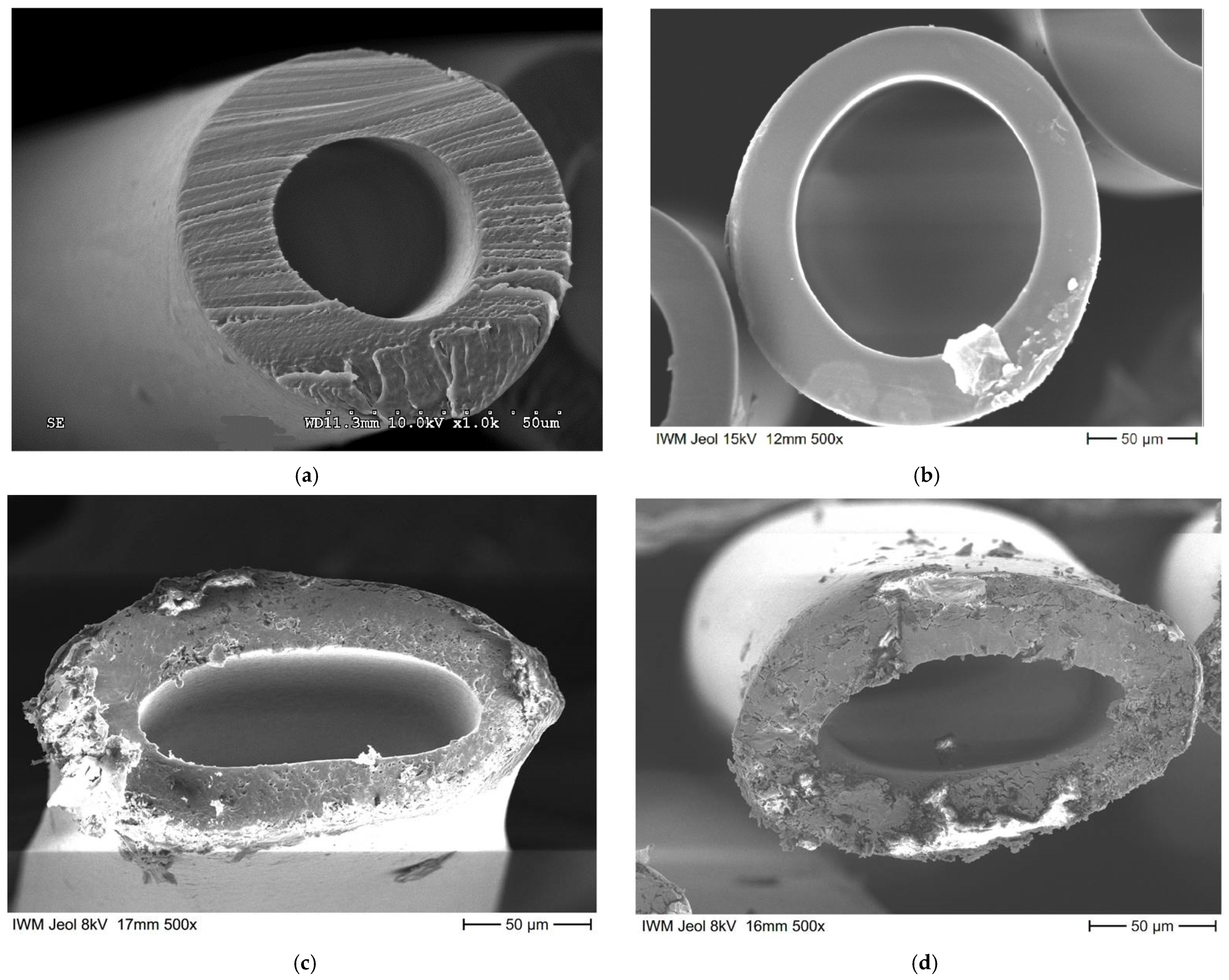
3.1. Effects of Post-Drawing on the Cross Section Geometry
The macrostructure of the obtained HF samples was studied using a scanning electron microscope (SEM) in order to qualitatively assess the morphology in the cross section.
Figure 7 shows the cross sections of the chosen HF samples based on PMP and industrial Graviton HFs for comparison.
As can be seen in
Figure 7, the samples HF_0 (undrawn) have highly uniform and round geometry, whereas samples HF_100_C (continuously drawn by 100% between un-heated (20 °C) godets) and HF_100_80 (continuously drawn by 100% at 80 °C godet temperature) after the post-processing (pulling of the fibers between the godets) demonstrate significant flattening of the fiber and loss of cylindricity. The geometric dimensions of the PMP HFs were averaged by 15 measurements of randomly chosen cross sections from different light microscopy images. The results are presented in
Table 2.
Based on the obtained photographs of cross-sections of HF samples and the calculated geometric dimensions, it can be concluded that post-drawing leads to decreasing of internal and external diameters, and this effect is stronger under conditions with HF heating. It is important to note that the laboratory HF internal diameter is bigger than the diameter of the Graviton HF. The larger diameters mitigate the risk of HF blocking due to the condensation of such components as vapors in separation processes(for example, water vapors, which was an issue in real applications) and additionally improve the hydrodynamics for using HFs as membrane contactors.
Based on the DSC analysis, the glass transition temperatures, melt temperatures and crystallinity degree (X
C, using heat of fusion ΔH
f) of samples of HFs based on PMP were determined, and data are presented in
Table 3. As it is seen from the obtained data, the conditions range of new fiber production does not affect the polymer T
g significantly. However, the value is slightly lower than the T
g of Graviton fibers. PMP can demonstrate the range of polymer properties, including glass transition temperature depending on the membrane preparation method (see
Table 4). It should be taken into account for the comparison of gas permeability and selectivity properties of different membranes based on PMP. Furthermore, it can be noted that HF post-drawing at 80 °C leads to a slight increase in PMP crystallinity degree instead of “cold” post-drawing.
3.2. Influence of Production Conditions on Gas Transport and Release Properties
Permeability of the CO
2/CH
4/N
2 (20/30/50 vol.%, respectively) gas mixture was measured to estimate the integrity of PMP HFs walls. The obtained gas permeability coefficients data at 23–25 °C are presented in
Table 4 in comparison with published data for PMP films.
As can be seen from the comparative
Table 4, the gas permeability coefficients of the studied PMP HFs are slightly lower than the values of the permeability coefficients of films from the same polymer. At the same time, the obtained gas selectivity data show good agreement between studied samples and with published values for PMP films, which proves the absence of defects in HFs walls and the quality of obtained HFs for its application as gas separation membranes.
3.3. Investigation of the Peculiarities of Permeability of Mixtures in Membrane Modules with PMP HFs
It is known from the literature data that the composition of the separated mixture can affect the transfer of gases through the polymer membrane [
14,
15,
16,
17]. Therefore, an experimental study of the gas separation properties of the HF_0 sample for CO
2/CH
4 and CO
2/N
2 mixtures with a variation of CO
2 concentrations in a wide range was carried out. The results are shown in
Table 5,
Table 6 and
Table 7.
As it can be seen from the experimental data, in general, the level of permeability of the components in the mixtures remains the same over the entire concentration range in the studied sample HF_0, which makes it possible to use new PMP HF membranes for future separating processes of gas mixtures of different origins and compositions.
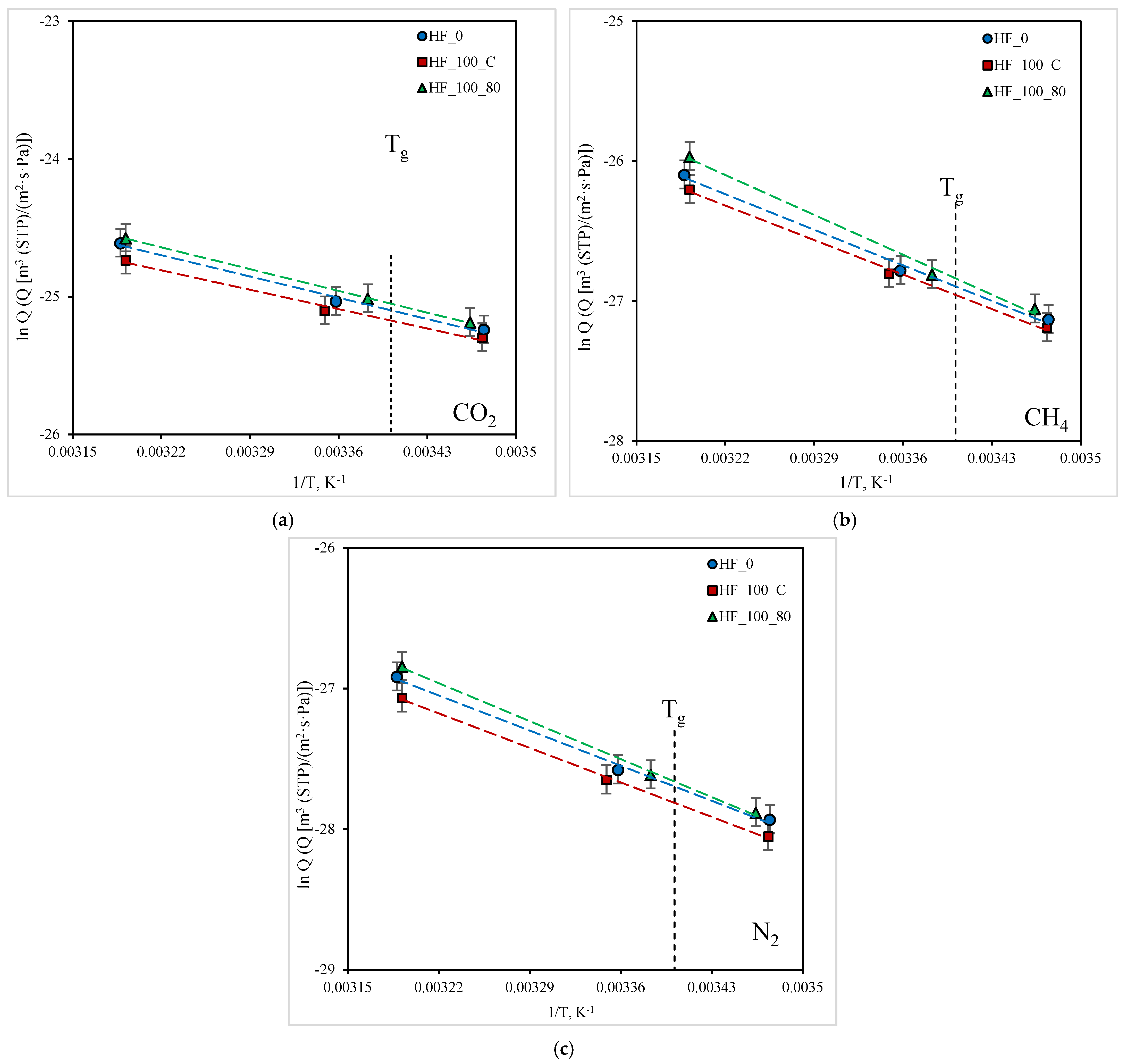
3.4. Effect of Temperature on the Gas Transport Properties of PMP HFs
To assess the prospects for the use of new membranes in various processes of gas separation, the temperature dependences of the permeability of gases are investigated in this work. Thus, in this work, the dependence of the permeance of the components in a ternary mixture CO
2/CH
4/N
2 (20/30/50 vol.%, respectively) for PMP HFs in the temperature range from 15 (below T
g) to 40 °C (above T
g) was obtained. The results are shown in
Figure 8.
Obtained data array represents new results of gas mixture transport in PMP for the specified temperature range. It is shown that temperature dependences are linear in Arrhenius coordinates and there are no visible deviations from linearity at the transition across T
g of the polymer, i.e., the permeability for the gases is insensitive towards T
g. There is a tendency to an increase in permeability with an increase in temperature for all studied gases. To make it possible to predict the transport and separation characteristics of the HFs and membrane modules based on them in a wide temperature range, the apparent activation energies of the permeability E
p of the studied gases for HFs samples was determined using an approximation of experimental dependences by Equation (4). The obtained values are presented in
Table 8.
It is shown that the level of gas permeability in the studied samples of PMP HFs does not vary a lot. However, for the post-drawn samples, the flattened shape leads to a significant increase in the hydrodynamic resistance and creates the danger of HF “collapse” in case of membrane module operation under high-pressure conditions. The results obtained for the permeability of the HF samples below and above Tg of the PMP make it possible to predict the separating properties in a wide temperature range.
4. Conclusions
A new set of hollow fiber gas separation membranes with a non-porous selective layer were obtained under various conditions using the melt spinning process as solvent-free technology. The influence of the production conditions on the fiber geometry was investigated. It was found that a spin head temperature of 280 °C and a specific mass throughput of 103 g mm−2 h−1 are optimal to obtain defect-free hollow fibers in a stable melt spinning process, using the given spinneret geometry and a winding speed of 25 m/min. The selected conditions provide the round cross-section of HF, which is favorable for sealing and allows to apply higher pressure in the shell side of the membrane module, whereas post-drawing leads to flattening of the fiber that increases the hydrodynamic resistance and creates the danger of HF collapse in the case of membrane module operation under high-pressure conditions. Comparative analysis of the geometry of new PMP HFs and those obtained from other manufacturers showed that the resulting larger cross section geometry of the new fibers with bigger inner diameter allows avoiding possible condensation of components of gas mixtures, for example, water vapor.
The parameters of the permeability of CO2, CH4, and N2 in gas mixtures were experimentally investigated. It was found that separation characteristics of HFs investigated in this work are close to the values reported in the literature for flat PMP membranes. The permeability of PMP for gas mixtures of different compositions with a variation of CO2 concentrations in a wide range was studied for the first time. It was found that the transfer of gas mixture components proceeds regardless of the mixture composition.
For all samples of PMP HFs, the temperature dependences of the permeability of the studied gases were obtained above and below the glass transition temperature of the polymer. Based on the temperature dependences, the apparent activation energies of the permeability of gases in PMP HFs have been determined, which makes it possible to predict gas transfer characteristics in a wide temperature range for modeling and optimization of separation processes.
Author Contributions
Conceptualization, D.A.S., V.V.T., M.G.S., T.G.; investigation, A.V.D., S.Y.M., M.P.; writing—original draft preparation, A.V.D.; writing—review and editing, D.A.S., M.P., S.Y.M., M.G.S.; supervision, D.A.S., V.V.T., M.G.S., T.G. All authors have read and agreed to the published version of the manuscript.
Funding
This research was funded by Russian Science Foundation, Grant No. 19-49-04105 and Deutsche Forschungsgemeinschaft, Grant No. GR1311/94-1.
Acknowledgments
The authors thank senior researcher G.A. Shandryuk for providing the DSC analysis.
Conflicts of Interest
The authors declare no conflict of interest. The funders had no role in the design of the study; in the collection, analyses, or interpretation of data; in the writing of the manuscript, or in the decision to publish the results.
References
- Baker, R.W. Membrane Technology and Application, 2nd ed.; John Wiley & Sons, Ltd: San Francisco, CA, USA, 2012; p. 574. [Google Scholar]
- Buller, K.-U. Heat and Heat-Resistant Polymers; Chemistry: Moscow, Russia, 1984; p. 1056. [Google Scholar]
- He, T.; Porter, R.S. Characterization of uniaxially drawn poly(4-methyl-pentene-1). Polymer 1987, 28, 1321–1325. [Google Scholar] [CrossRef]
- Chen, X.Y.; Vinh-Thang, H.; Ramirez, A.A.; Rodrigue, D.; Kaliaguine, S. Membrane gas separation technologies for biogas upgrading. RSC Adv. 2015, 5, 24399–24448. [Google Scholar] [CrossRef]
- Kostrov, J.A.; Mostrova, G.B.; Ignatienko, T.I.; Arbashnikov, A.J.; Khutorski, B.I. Graviton hollow gas-separating fibre. Fibre Chem. 1987, 18, 479–481. [Google Scholar] [CrossRef]
- Abedini, R.; Omidkhah, M.; Dorosti, F. Hydrogen separation and purification with poly(4-methyl-1-pentene)/MIL 53 mixed matrix membrane based on reverse selectivity. Int. J. Hydrogen Energy 2014, 39, 7897–7909. [Google Scholar] [CrossRef]
- Nematollahi, M.H.; Dehaghani, A.H.S. CO2/CH4 separation with poly(4-methyl-1-pentyne) (TPX) based mixed matrix membrane filled with Al2O3 nanoparticles. Korean J. Chem. Eng. 2016, 33, 657–665. [Google Scholar] [CrossRef]
- Wolinska-Grabczyk, A.; Jankowski, A.; Sekuła, R.; Kruczek, B. Separation of SF6 from binary mixtures with N2 using commercial poly(4-methyl-1-pentene) films. Sep. Sci. Technol. 2011, 46, 1231–1240. [Google Scholar] [CrossRef]
- Mitsui Chemical, Inc. Available online: https://us.mitsuichemicals.com/index.htm (accessed on 22 May 2021).
- Pelzer, M.; Vad, T.; Becker, A.; Gries, T.; Markova, S.; Teplyakov, V. Melt spinning and characterization of hollow fibers from poly(4-methyl-1-pentene). J. Appl. Polym. Sci. 2021, 138, 49630. [Google Scholar] [CrossRef]
- Mohr, J.M.; Paul, D.R.; Mslna, T.E.; Lagow, R.J. Surface fluorination of composite membranes. Part I. Transport properties. J. Membr. Sci. 1991, 55, 131–148. [Google Scholar] [CrossRef]
- Puleo, A.C.; Paul, D.R.; Wong, P.K. Gas sorption and transport in semicrystalline poly(4-methyl-1-pentene). Polymer 1989, 30, 1357–1366. [Google Scholar] [CrossRef]
- Markova, S.Y.; Beckman, I.N.; Teplyakov, V.V. Diffusion of C1-C3 Alkanes in Semicrystalline Poly(4-Methyl-1-Pentene) as a Two-Phase Polymeric System. Int. J. Mem. Sci. Tech. 2017, 4, 28–36. [Google Scholar]
- Sridhar, S.; Veerapur, R.S.; Patil, M.B.; Gudasi, K.B.; Aminabhavi, T.M. Matrimid polyimide membranes for the separation of carbon dioxide from methane. J. Appl. Polym. Sci. 2007, 106, 1585–1594. [Google Scholar] [CrossRef]
- Donohue, M.D.; Minhas, B.S.; Lee, S.Y. Permeation behavior of carbon dioxidemethane mixtures in cellulose acetate membranes. J. Membr. Sci. 1989, 42, 197–214. [Google Scholar] [CrossRef]
- Yeom, C.K.; Lee, S.H.; Lee, J.M. Study of transport of pure and mixed CO2/N2 gases through polymeric membranes. J. Appl. Polym. Sci. 2000, 78, 179–189. [Google Scholar] [CrossRef]
- Markova, S.Y.; Pelzer, M.; Shalygin, M.G.; Vad, T.; Gries, T.; Teplyakov, V.V. Gas separating hollow fibres from Poly(4-methyl-1-pentene): A new development. Sep. Purif. Technol. 2022, 278, 119534. [Google Scholar] [CrossRef]
Figure 1.
Structural formula of poly(4-methyl-1-pentene).
Figure 1.
Structural formula of poly(4-methyl-1-pentene).
Figure 2.
Installation for obtaining HF with a spinneret head with 4 coaxial holes with air supply to the internal space of the HF.
Figure 2.
Installation for obtaining HF with a spinneret head with 4 coaxial holes with air supply to the internal space of the HF.
Figure 3.
Scheme of coaxial holes of spinneret for the HFs preparation.
Figure 3.
Scheme of coaxial holes of spinneret for the HFs preparation.
Figure 4.
Setup for the fiber cold and hot post drawing.
Figure 4.
Setup for the fiber cold and hot post drawing.
Figure 5.
Laboratory-scale membrane module with PMP HFs.
Figure 5.
Laboratory-scale membrane module with PMP HFs.
Figure 6.
Scheme of the experimental setup for determining gas transport parameters: (1) thermocryostat (Huber CC 410), (2) HF membrane cell, (3) gas chromatograph (Crystal 2000m).
Figure 6.
Scheme of the experimental setup for determining gas transport parameters: (1) thermocryostat (Huber CC 410), (2) HF membrane cell, (3) gas chromatograph (Crystal 2000m).
Figure 7.
Cross section of HFs based on PMP: (a) Graviton HF; (b) HF_0 (undrawn); (c) HF_100_C (continuously drawn by 100% between unheated (20 °C) godets); (d) HF_100_80 (continuously drawn by 100% at 80 °C godet temperature).
Figure 7.
Cross section of HFs based on PMP: (a) Graviton HF; (b) HF_0 (undrawn); (c) HF_100_C (continuously drawn by 100% between unheated (20 °C) godets); (d) HF_100_80 (continuously drawn by 100% at 80 °C godet temperature).
Figure 8.
Dependence of CO2, CH4, and N2 permeance on temperature in Arrhenius coordinates for the studied HF samples: (a) CO2; (b) CH4; (c) N2.
Figure 8.
Dependence of CO2, CH4, and N2 permeance on temperature in Arrhenius coordinates for the studied HF samples: (a) CO2; (b) CH4; (c) N2.
Table 1.
Setup and melt spinning parameters for obtaining HF based on PMP.
Table 1.
Setup and melt spinning parameters for obtaining HF based on PMP.
Volumetric Polymer Feed (cm3/Rotation) | Extruder Rotation Speed (Rotations/min) | Spin Head Temperature (°C) | Specific Mass Throughput (g mm−2 h−1) | Winding Speed (m/min) |
---|
0.16 | 13.13 | 280 | 103 | 25 |
Table 2.
Basic geometric dimensions of hollow fibers PMP.
Table 2.
Basic geometric dimensions of hollow fibers PMP.
HF Sample | Process Conditions | Internal Diameter (µm) | External Diameter (µm) | Wall Thickness (µm) |
---|
Graviton HFs | | 40 | 80 | 20 |
HF_0 | see Table 1 | 111 | 187 | 38 |
HF_100_C | continuously drawn by 100% between unheated (20 °C) godets | 93 | 173 | 40 |
HF_100_80 | continuously drawn by 100% at 80 °C godet temperature | 88 | 141 | 27 |
Table 3.
DSC analysis results of the PMP HFs samples used in experiments.
Table 3.
DSC analysis results of the PMP HFs samples used in experiments.
Sample | XC | Tg, °C | Tm, °C | ΔHf, (J g−1) |
---|
Graviton HF | 0.54 | 30 | 235 | 33.5 |
HF_0 | 0.32 | 21 | 227 | 20.0 |
HF_100_C | 0.32 | 22 | 227 | 19.6 |
HF_100_80 | 0.36 | 23 | 227 | 22.1 |
Table 4.
Comparative table of gas permeability coefficients in PMP at 23–25 °C.
Table 4.
Comparative table of gas permeability coefficients in PMP at 23–25 °C.
Gas | CO2 | CH4 | N2 | Selectivity | Ref. |
---|
Sample | Permeability Coefficient, Barrer * | CO2/CH4 | CO2/N2 | |
PMP film | 108 | 20.1 | 8.50 | 5.4 | 12.7 | [11] |
PMP (Q) (Xc = 0.51; Tg = 30 °C) | 108 | 19.8 | 9.26 | 5.5 | 11.7 | [12] |
PMP (S) (Xc = 0.61; Tg = 27 °C) | 85.0 | 14.0 | 6.74 | 6.1 | 12.6 |
PMP (A) (Xc = 0.76; Tg = 22 °C) | 74.0 | 13.0 | 5.93 | 5.7 | 12.5 |
PMP (H) (Xc = 0.68; Tg = 37 °C) | 82.0 | 14.2 | 6.68 | 5.8 | 12.3 |
PMP (2.5X) (Xc = 0.38; Tg = 40 °C) | 86.0 | 14.6 | 6.55 | 5.9 | 13.1 |
PMP (10X) (Xc = 0.20; Tg = 53 °C) | 68.0 | 10.5 | 5.02 | 6.5 | 13.5 |
PMP film (Xc = 0.69; Tg = 29.7 °C) | - | 14.0 | - | - | - | [13] |
PMP Graviton HFs | 42.3 | 7.3 | 4.5 | 5.8 | 9.4 | This work |
PMP HF_0 | 68.4 | 12 | 5.37 | 5.7 | 12.7 | This work |
PMP HF_100_C | 67.1 | 12.2 | 5.26 | 5.5 | 12.8 | This work |
PMP HF_100_80 | 48.7 | 8.1 | 3.62 | 6.0 | 13.5 | This work |
Table 5.
Permeance of CO2/CH4 mixtures of various compositions at 25 °C.
Table 5.
Permeance of CO2/CH4 mixtures of various compositions at 25 °C.
CO2/CH4 Mixture Composition, % vol. | 100/0 | 90/10 | 27/73 | 10/90 | 0/100 |
---|
Q(CO2)·1012, m3 (STP)/(m2·s·Pa) | 24.1 | 24.6 | 21.8 | 25.2 | – |
Q(CH4)·1012, m3 (STP)/(m2·s·Pa) | – | 3.9 | 4.1 | 3.9 | 3.8 |
Table 6.
Permeance of CO2/N2 mixtures of various compositions at 25 °C.
Table 6.
Permeance of CO2/N2 mixtures of various compositions at 25 °C.
CO2/N2 Mixture Composition, % vol. | 100/0 | 27/73 | 15/85 | 12/88 | 0/100 |
---|
Q(CO2)·1012, m3 (STP)/(m2·s·Pa) | 24.1 | 21.6 | 22.8 | 23.5 | – |
Q(N2)·1012, m3 (STP)/(m2·s·Pa) | – | 1.6 | 1.7 | 1.8 | 1.6 |
Table 7.
Selectivity of separation of CO2/CH4 and CO2/N2 mixtures at 25 °C.
Table 7.
Selectivity of separation of CO2/CH4 and CO2/N2 mixtures at 25 °C.
Composition of the Mixture, % vol. | 90/10 | 27/73 | 15/85 | 12/88 | 10/90 | αid |
---|
| Mixture Selectivity (α) | |
CO2/CH4 | 6.3 | 5.3 | – | – | 6.4 | 6.4 |
CO2/N2 | – | 13.3 | 13.5 | 13.3 | – | 15.2 |
Table 8.
Apparent activation energies of permeability Ep for CO2, CH4, and N2 in PMP HFs.
Table 8.
Apparent activation energies of permeability Ep for CO2, CH4, and N2 in PMP HFs.
Gas | EP, kJ/mol |
---|
| HF_0 | HF_100_C | HF_100_80 |
CO2 | 16.7 | 18.4 | 18.8 |
CH4 | 29.3 | 30.2 | 33.9 |
N2 | 29.2 | 29.6 | 32.1 |
| Publisher’s Note: MDPI stays neutral with regard to jurisdictional claims in published maps and institutional affiliations. |
© 2021 by the authors. Licensee MDPI, Basel, Switzerland. This article is an open access article distributed under the terms and conditions of the Creative Commons Attribution (CC BY) license (https://creativecommons.org/licenses/by/4.0/).