Abstract
The impact resistance of functionally layered two-stage fibrous concrete (FLTSFC) prepared using the cement grout injection technique was examined in this study. The impact resistance of turtle shells served as the inspiration for the development of FLTSFC. Steel and polypropylene fibres are used in more significant quantities than usual in the outer layers of FLTSFC, resulting in significantly improved impact resistance. An experiment was carried out simultaneously to assess the efficacy of one-layered and two-layered concrete to assess the effectiveness of three-layered FLTSFC. When performing the drop-mass test ACI 544, a modified version of the impact test was suggested to reduce the scattered results. Instead of a solid cylindrical specimen with no notch, a line-notched specimen was used instead. This improvement allows for the pre-definition of a fracture route and the reduction of the scattering of results. The testing criteria used in the experiments were impact numbers associated to first crack and failure, mode of failure, and ductility index. The coefficient of variation of the ACI impact test was lowered due to the proposed change, indicating that the scattering of results was substantially reduced. This research contributes to the idea of developing enhanced, more impact-resistant fibre composites for use in possible protective structures in the future.
1. Introduction
New composite materials and processes are transforming the building industry at breakneck speed [,]. One novel approach is a bionic-inspired, functionally graded composites. Researchers have discovered these biomaterials’ unique hierarchical architectures with excellent impact strength. Research in biomimicry, or the use of biological materials, is a new trend in material technology. Biomimicry and increased impact resistance may be achieved by using composite concrete materials (e.g., the carapace of turtle). Complex spatially organized organic and inorganic nano/micro/mesoscale structures. The turtle shell protects them from impact and allows them to move freely. The endocortic layer is thick and shielding, while the porous middle layer serves as absorber of impact. The third layer is dense and foreign; it shields. The endocortical layer resists piercing while the trabecular layer absorbs the given stress.
1.1. Literature Review
A standard composite material in the construction industry is fibre reinforced concrete (FRC), which improves the efficiency of concrete structures exposed to different impact loads [,]. FRC is the potential for enhancing impact-resistant applications in essential constructions such as flooring, nuclear storage, and airplane pavements []. An intense explosion may not harm the buildings, but repeated collisions can cause damage and collapse []. Increasing made-made risks have forced the construction of high impact resistance infrastructure subjected to repeated crashes and explosions []. Several studies have been conducted on FRC, which can withstand a higher impact than normal concrete [,,]. In general, the engineering qualities of steel FRC are influenced by several factors, including the aspect ratio, length, shape, dosage of fibre, and the parameters of the cement matrix properties []. Steel FRC’s compressive strength was unaffected by a fibre dosage of up to 1%, although flexural and splitting strength was significantly increased []. Many engineering properties may benefit from adding fibres to concrete, namely resistance to fatigue and impact loading, thermal shock strength, fracture toughness, torsion, and flexural strength [,,]. Kazemi et al. [] reported that the addition of steel fibres to concrete led to a significant improvement in the fracture energy and ductility of high-strength concrete. Previous research has demonstrated that adding steel fibres into concrete [,] prevents brittle fracture by enhancing tensile strength and toughness and inhibits crack development and propagation by bridging the fibres.
Composites such as two-stage fibrous concrete (TSFC) have been developed as a result of advances in material science and unification []. The TSFC is a particular kind of composite that is cast utilizing a unique casting method that is not used for normal concrete []. Fibres and coarse aggregate volume were prepacked in the formwork, followed by a flowable grout are used to fill up the voids between the fibres and aggregates []. Increasing the concentration of coarse aggregate in TSFC improves the concrete’s properties by increasing aggregate contact points and improving stress distribution []. Murali and Ramprasad (2018) [] investigated the impact resistance of multilayer TSFC slabs. Three-layered TSFC slabs had 4% and 2% different fiber doses, correspondingly for top, bottom, and intermediate layers. The results showed that TSFC could absorb impact energy well, reducing breakability and delaying fracture formation and expansion. The possible use of this kind of concrete in the building industry has been extensively researched. TSFC is now being advanced as functionally layered fibre concrete (FLFC).
Functionally graded concrete (FGC) is a new kind of composite material that has been developed as a consequence of modern material technology. FGC is a new composite with improved mechanical qualities as well as the requisite performance attributes []. Functionally layered fibrous concrete (FLFC) offers excellent toughness and resistance to impact. Beams with three layers of FLFC made of customised cementitious composite comprising 1.5% and 0.5% polyvinyl alcohol were examined by Sridhar and Prasad (2019) []. The findings revealed that the multi-layered FLFC beams exhibited 36% more strength than a normal beam. Moghadam and Omidinasab (2020) [] studied the impact behavior of FLFC slabs having 1% nylon and 1% steel fibres. Steel fibre showed a greater increase in FLFC flexural strength than nylon fibre. Flexural strength was improved by 1.7, 2.6, and 1.2 times, respectively, using hybrid, steel, and nylon fibres. FLFC outperformed conventional fibrous concrete in flexural strength. Prasad and Murali (2021) [] studied the effect of drop mass impact on three-layered FLFC cylindrical specimens. Three-layered FLFC specimens with different polypropylene and steel fibre dosages were made. The greatest impact resistance was observed in three-layered FLFC specimens with 3.6% in the top and bottom layers and 0% steel fibre content in the intermediate. Multi-layered specimens had a 39% higher failure impact strength than single-layered specimens made from identical steel fibres. The researchers used layered fibre composite designs with higher dosages of fibre on the top and bottom layers to improve fiber efficiency and impact resistance. There is a limited amount of research available on the production of FLFC utilizing two-stage concrete. More research is required to further understand this material’s energy absorption and impact capabilities properly.
1.2. Impact Test Methods and Modifications
Several test methods for measuring FRC impact resistance have been reported (ACI 544-2R, 1984) [,]. Charpy pendulum, projectile, blast, and drop mass are examples. An easier method for assessing the impact resistance of FRCs is provided by the drop-mass test in the (ACI 544-2R, 1984) [] standard. A cylindrical specimen is fractured with a constant impact force. The following variables caused significant dispersion in experimental findings from the ACI 544 testing method [,,,]: (1) Detection of a crack’s commencement and final crack may be done visually, and it can occur in any direction at all []. (2) A single point of impact on the concrete’s surface yields the impact strength value []. (3) Concrete’s non-homogeneity leads to a mix of design inconsistencies and impact strength dispersions []. (4) This test also included exercise performance, such as pulling and dropping a 4.54 kg load from a certain height []. Dropping a 4.54 kg steel ball from 457 mm above the specimen’s top surface is part of the ACI 544 drop weight testing procedure. The cylindrical specimen is 76 mm in radius and 64 mm in thickness, respectively. In Figure 1, a solid steel plate holds the specimen, and four positioning lugs prevent the sample from moving to the left or right. A positioning bracket is used to attach a 63.5 mm steel ball that is put on the specimen to distribute stress evenly throughout the surface. The test specimen cracks and fails, and this is documented on the test specimen.
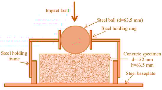
Figure 1.
A drop weight impact test suggested by ACI 544.
This research examines the top two sources of inaccuracy and suggests solutions. The following variables were found by Badr and Ashour []: (i) The cause of variation may be the proper specimen preparation techniques. ACI 544 recommends that disc specimens for concrete compressive strength may be cast or cut from standardized cylinders. (ii) According to the criteria for determining specimen failure, the impact may be stopped before or after failure, causing errors in the impact numbers. Furthermore, there are no guidelines for preventing mechanisms of failure. (iii) Dispersion of results may be caused in two different ways by the applied impact force on the steel ball at the centre.
- It enables the development of fractures in any direction, making the first visible crack more challenging to identify.
- Although concrete is a composite mixture, the concentrated force may hit a soft mortar area or a solid grain of coarse aggregate. As a result, findings may not correctly represent the impact strength of material.
The top surface of the specimens with a line-edged notch and a line-load transmitting plate are shown in Figure 2. When the hammer is continually dropped on the transmitting steel plate, it has a greater impact force since it is scattered across a wider area. Second, specimens may split in half without numerous radial cracks appearing when fractures occur parallel to the contact line. This modification decreased the dispersion of data by defining the fractured path and specimen failure.
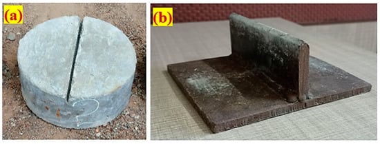
Figure 2.
Modification proposed (a) Notched specimen, (b) Line-load transmitting plate.
2. Significance of Research
This paucity of knowledge is seen in the bibliography of materials for ACI modified drop-weight testing. Although this is the case, investigators all around the globe have used a variety of statistical techniques to analyse the significant scattering in the ACI drop-weight test results. It is an attractive experience to go through the altered impact test and come to a reasonable decision about how to lessen dispersion outcomes. However, only a few studies have been conducted to determine if adding granular bedding may help reduce dispersion results, and there are still several gaps in this field of study. As a result, this study aimed to examine the impact resistance of FLTSFC by using an altered impact test approach in order to bridge these research gaps. A straightforward method for reducing dispersion effects is proposed. In this case, a line knife plate and a notched specimen are used, rather than the conventional without notched specimen and steel ball.
3. Experimental Program
3.1. Raw Materials
- Portland Pozzolana Cement, obtained from Dalmia cement, was used to make FLTSFC. It met the requirements of (Bureau of Indian Standard (BIS), Manak Bhawan, Old Delhi, 1991) [].
- Conforming to the specifications of IS 383 (2016) [], natural river sand was utilized as the fine aggregate. The specific gravity of 2.65 and a fineness modulus of 2.41 of used aggregate, as specified by the standard ASTM:C939-10 (2010) []. The fine aggregate particle size was less than 2.36 mm, so that the grout enters the fibre skeleton and aggregates via gravity.
- Crushed granite gravel with a particle size of 12.5 mm is used to make coarse aggregate, according to IS 383 (2016) []. Water absorption was 0.56%, the specific gravity was 2.69, and the apparent bulk density was 1700 kg/m3 for coarse aggregate.
- The flowable cement grout was made possible by the employment of Tech Mix 640 high-range super plasticizing ingredient, with a dose ranging from 0.35% to 0.45% of cement weight, to satisfy the efflux time of the grout. The mixing combination of materials is shown in Table 1.
 Table 1. Mixing composition of the composite.
 - The tensile strength of composite was improved by adding two distinct fibres. A polypropylene fibre (PF) with a tensile strength of 500 MPa, a length of 45 mm, and a diameter of 0.8 mm was used. Steel fibre (SF) with a diameter of 1 mm, length of 50 mm, and strength of 1150 MPa was used. The appearance of two distinct fibres utilized in this research is shown in Figure 3. The average dosage of fibre was restricted to 2.4% owing to low-density fibre utilisation (PF). The dose of PF above 2.4% removes the additionally aggregates placed into the formwork. The idea of two-stage fibrous concrete was updated as slurry infiltrated fibrous concrete (SIFCON). This study focuses solely on impact performance of functionally graded two-stage fibrous concrete beams. To prevent creating SIFCON, an average fibre dose is restricted to 2.4% in this research.
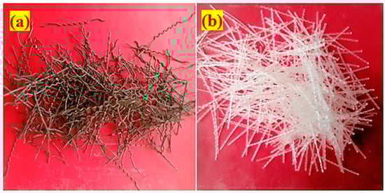 Figure 3. Fibre appearance (a) Steel fibre and (b) Polypropylene fibre.
3.2. Mixing Composition
The current research tested the impact resistance of 12 diverse concrete mixtures. According to ASTM:C939-10, (2010) [] guidelines, a grout efflux time ranged between 35 and 40 s to achieve a flowable grout. Numerous grout mixing cone tests were performed to obtain the efflux time of 37 ± 2 s. For water to cement (w/c) and cement to sand (c/s), the optimum ratios were 0.45 and 1, respectively. Grout flowability was improved by adding a high-quality water reducer to the water at a concentration of 0.35% and 0.45% for non-fibrous and fibrous specimens, respectively. It is seen in Table 1 that each layer of FLTSFC has a different fibre scheme and dosage. The initial combination was designated PAC as a fibre-free control specimen. SF and PF were used in the second and third mixtures and were made using single-layer PAFC, containing a 2.4% dose of PF and SF, respectively, and labelled S-SF and S-PF. The fourth combination was made using a two-layer FLTSFC with SF and PF at the top and bottom layers, respectively, while mixture five was likewise a two-layer FLTSFC reverse the PF and SF addition. Mixtures four and five were assigned the names D-SF-PF and D-PF-SF, respectively. T-FG1–T-FG7 were the last seven combinations, three-layered FLTSFCs with a 2.4% dose and a variety of fibre schemes, which were tested.
3.3. Specimen Preparation
The impact strength was calculated using 152 mm diameter and 64 mm thick cylindrical specimens. As illustrated in Figure 4, the FLTSFC casting process has the following stages. Figure 4a depicts an empty cylindrical mould resting on a level platform with oil applied to all interior surfaces of the mould. Figure 4b depicts the placement of premixed aggregates and fibres into an empty mould in order to build a natural skeleton. As a further step, the cement grout was poured over the top of the skeleton and allowed to fill up the spaces as gravity worked its way through the structure, as illustrated in Figure 4c. Finished specimens after grouting and inserted notch plate are displayed in Figure 4d. The demolded specimen after 24 h is shown in Figure 4e. Before testing, the specimens were subjected to a 28-day curing period in water.
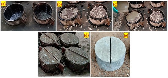
Figure 4.
Casting procedure of FLTSFC.
3.4. Drop-Mass Impact Testing Device
The impact strength of the FLTSFC specimens was determined using a modified drop-mass impact test in line with ACI 544-2R, which was developed by the American Concrete Institute in 1984 []. Importantly, ACI 544 recommended testing is an uncomplicated test that does not require the use of shaking, deformations, or additional measurements other than the number of impacts. According to the modified impact test procedure, a 4.45 kg steel hammer must be hoisted to a height of 457 mm and dropped freely against the top of a line-load transmitting steel plate that has been placed on top of the notched specimen. The specimen’s lateral movement was restricted by placing it on a steel plate of four-legged. The modified drop-weight testing device that was employed in this study is depicted in Figure 5. The impact numbers associated with first crack (Q1) and failure (Q2) were recorded through the visual examination. When a fracture reaches the bottom specimen, it is classified as a failure and is divided into two pieces.
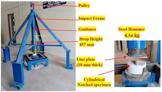
Figure 5.
Impact testing device.
4. Results and Discussion
4.1. Compressive Strength of FLTSFC
In line with IS 516:2014 [], the mean compressive strength of three 100 mm cubes is shown in Table 2. As seen in Figure 6, all FLTSFC specimens demonstrated an increase in compressive strength over the control specimen. The compressive strength of S-SF & S-PF specimens containing 2.4% SF and PF were increased by 59% and 19%, respectively, compared to PAC specimens. As a result of the greater dosage of fibre (2.4 percent) provided in the full cross-section, the bonding activity of fibre in the damaged region is enhanced, which postpones crack initiation and development [,].
Table 2.
Compressive strength results.
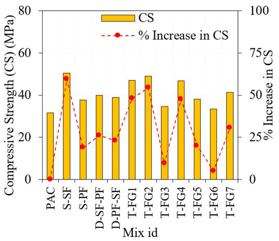
Figure 6.
Observed compressive strength of FLTSFC.
Compared to PAC, the compressive strength was improved by 23% and 26% for the specimens D-PF-SF and D-SF-PF, respectively. However, evenly distributed SF and PF at the top or bottom layers could avoid macro fractures, increasing compressive strength []. The load distribution on the concrete’s outer layers modified the fracture route and decreased the development of crack by the action of fibre bridging []. There is a noticeable improvement in compressive strength from three-layer FLTSFC reinforced with various fibre dosages, and the strength varies from 5% to 54%, compared to PAC. Among the three-layer FLTSFC specimens, the T-FG2 with 1.6% SF in the middle layer and 2.8% SF in the top and bottom layers displayed the best compressive strength. Because of the large amount of SF at outer layers, their compressive strength has been improved as well. All such three-layered FLTSFC specimens improved compressive strength were recorded based on increased quantities of mono and hybrid fibres. The fibre dosage in the normal concrete is limited to 2% owing to workability problems, nonuniform fibre dispersion, and fibre balling. This phenomenon creates a void formation and developing crack begins at the micro-scale []. Pre-placing a greater amount of coarse aggregates and fibres in the mould before grout pouring is a feature of the FLTSFC production technique that eliminates this problem []. In summary, SF and PF positively influenced the compressive strength for the single-layered specimens to a greater extent than the two and three-layered FLTSFC. A higher dose of fibres is added into layers, leading to increased resistance to crack growth and propagation. This innovative manufacturing method ensured consistent distribution, eliminating clustering and fibre balling []. The imperative increase in compressive strength of FLTSFC over PAC is due to a greater fibre dose (2.4%).
4.2. Impact Test Results
Table 3 demonstrates the impact numbers associated with first crack (Q1) and failure (Q2) for the twelve different mixtures. The mean of fifteen specimens was used for discussion.
Table 3.
Results from the experimental impact test.
4.2.1. Effect of Single-Layered Concrete
Table 2 and Figure 7 shows the impact strength of a single-layered specimen. For the reference specimen (PAC), the recorded Q1 and Q2 were 17 and 29, respectively. Adding fibre to concrete improves its impact strength significantly.
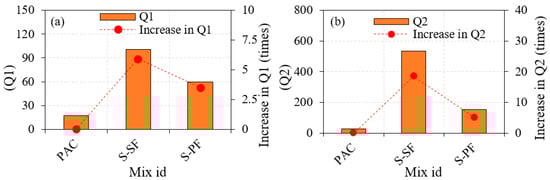
Figure 7.
Impact strength of a single-layered specimen.
- The S-SF specimen exhibited a Q1 value around 101 and Q2 around 536. These observed values were 5.94 and 18.48 times larger than PAC specimens, respectively.
- The S-PF specimen exhibited a Q1 value of 60 and Q2 of 152. Values obtained from this specimen were 3.53 and 5.24 times higher than those from the PAC specimen, respectively.
- S-SF specimen showed improved Q1 and Q2 values by about 1.68 and 3.7 times, respectively, with respect to the S-PF specimen.
After fracture development, SF in concrete may effectively prevent macro-crack propagation and transfer tensile loads. PF addition was also bridges microcracks and slowed their growth by interacting with the matrix and fibres []. The increased Q1 and Q2 due to a higher fibre dose (2.4%) resulted in improved ductility.
4.2.2. Effect of Double-Layered FLTSFC
The impact strength of the two-layered FLTSFC is shown in Figure 8a,b. Compared to PAC specimens, the double-layered FLTSFC exhibited excellent impact strength.
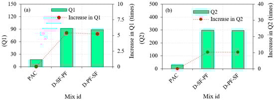
Figure 8.
Impact strength of double-layered FLTSFC.
- The recorded values were 92 and 299, corresponding to Q1 and Q2 for the D-SF-PF specimen. With respect to PAC specimen, the recorded Q1 value improved by 5.41 times and Q2 by 10.31 times.
- The Q1 and Q2 of the D-PF-SF specimens recorded were 89 and 296, respectively. These values were 5.24 times higher in Q1 and 10 times higher in Q2.
The two-layered FLTSFC with SF and PF at the outer layers showed superior impact resistance, improved ductility, and eradicates brittleness []. A top layer of the two-layered FLTSFC with 2.4% SF dosage performed a major influence in modifying the process of cracking in D-SF-PF than D-PF-SF. Because of the greater amount of SF existence in the top layer and impact point, higher impact energy is absorbed. Bridge action between the FLTSFC’s matrix and SF results in improved stiffness and pull-out resistance of fibre from the surrounding matrix, improved performance of crack resistant, and transference of tensile stress effectively along the FLTSFC’s top layer damaged segments []. Contrarily, top-layer comprised PF contributed to rapid cracking, which proliferated to the bottom-layer comprised SF. The impact resistance performance of the D-PF-SF specimen is marginally lower than D-SF-PF specimen. Because of the crack-bridging action of the SF fibres, both the PF-SF and PF-SF specimens exhibited higher Q1 and Q2 values, which had an impact on the fracture stabilisation process. Consequently, this enhanced fibre debonding, sliding, and pulling out, as well as the delay in the development of fractures [,]. It was found that the two-layered FLTSFC specimens had a lower impact strength compared to the single-layered S-SF specimens. The single-layered concrete specimen comprised even SF/PF dispersed throughout the cross-section, while the two-layered FLTSFC specimen had just one layer of SF/PF.
4.2.3. Effect of Three-Layer FLTSFC
The three-layered FLTSFC specimens impact strength in terms of Q1 and Q2 are shown in Figure 9a,b, respectively. Compared to PAC specimen, all FLTSFC specimens demonstrated a significant improvement in Q1 and Q2 values.
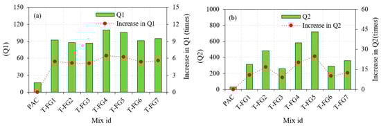
Figure 9.
Impact strength of triple-layered specimen.
- For T-FG1 specimen, the recorded Q1 value was 92 and Q2 was 313. These two values were improved by 5.41 and 10.79 times higher with respect to PAC specimen.
- T-FG2 specimen exhibited an impact strength of 88 and 483 corresponding to Q1 and Q2, respectively. In comparison with PAC specimen, the recorded values were 5.18 and 16.65 times higher.
- For T-FG3 specimen, the recorded Q1 value was 87 and Q2 value was 260. These two impact strength values were enhanced by 5.12 and 8.96 times, respectively.
- The T-FG4 specimen displayed a Q1 value of 110 and Q2 value of 583. These values were improved by about 6.47 and 20.10 times, respectively.
- The T-FG5 specimen has the maximum Q1 and Q2 values ever recorded, with the highest being 106 and 720, respectively. When compared to PAC, the values were improved by 24 and 24.82 times, respectively.
- For the T-FG6 specimen, the recorded Q1 and Q2 values were 91 and 292, respectively. There was an increase in the values observed by 5.35 and 10.07 times, respectively.
- In the case of the T-FG7 specimen, the Q1 and Q2 values were 95 and 360, respectively. The numbers were multiplied by 5.59 and 12.41 times, respectively.
When compared to PAC, all FLTSFC showed superior impact resistance. The T-FG5 specimens exhibited the maximum Q1 and Q2 values. In terms of Q1 fracture toughness efficiency, the T-FG4 sample was the best, with a hybrid SF + PF mixture of 2.8% at the top and bottom layers and 1.6% at the middle layer. Functionally graded concrete retains greater impact energy than cross-sections with the same quantity of fibre in full-reinforced cross-sections. This may be because the specimen’s top surface may be capable strain withstanding greater amounts of tensile waves [,]. Higher fibre doses enhanced tensile properties in both outer layers, leading to good impact resistance. The T-FG5 specimen’s failure strength was improved due to the greater dosage of SF at outer layers. The ductile FLTSFC specimen was intended to micro-crack to reduce energy waves with enormous tensile stress waves at the top and bottom layers. It was noted that greater SF dosages used in the top and bottom layers exhibited an increase in tensile strength and provide greater impact energy engrossment capacity via membrane action, therefore dispersing impact stress more widely []. The goal of FLTSFC is to sustain the development of finely structured materials capable of meeting the performance requirements of structural components. The different fibre doses applied to each layer of concrete give it unique properties and the shear stress is transferred through interfacial transition zones. The addition of layers may improve composite action by reducing shear stress transfer. The ultimate limit state required all three layers to functions together, indicating an excellent bond. A rigid layer was produced at the point of impact with a higher dose of fibres []. In comparison with PAC specimen, the findings demonstrated that the varied SF and PF doses used in FLTSFC greatly enhanced the impact energy absorption capability.
4.2.4. Ductility Index (IDI) of FLTSFC
The IDI is determined by dividing Q2 by Q1 [], and the IDI results for all possible combinations are depicted in Figure 10. The IDI value for the PAC specimen in Figure 10 was 1.7, indicating that the specimen had insufficient post-cracking resistance. The PAC specimens immediately broke into two halves. S-SF and S-PF specimens showed IDI values of 5.31 and 2.53, respectively, representing that the specimens comprised of SF rather than PF exhibited excellent post-crack resistance. However, the three-layered FLTSFC displayed an outstanding post-crack resistance ranging from 2.98 to 6.79. Fibres prevent the fracture point from opening inside the concrete, reducing brittleness and slowing crack development []. The higher fibre dose in FLTSFC causes a ductile failure. A high IDI number implies good ductility, whereas a low IDI suggests brittleness [].
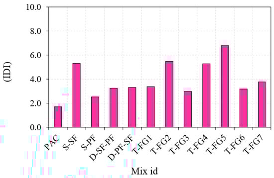
Figure 10.
Impact ductility index.
4.2.5. Failure Pattern
Figure 11 depicts the fracture of FLTSFC at the top (T) and side (S) faces. The fibre-free control specimen was divided into two fragments, and brittle failure was observed. As demonstrated in Figure 11a,b, when a line-notched specimen is impacted, the fracture propagates via the notch tip and eventually reaches the specimen bottom surface after numerous impacts. A ductile failure was seen in the behaviour all FLTSFC specimens, and the stress transfer capacity across developed fractures was greatly boosted by the addition of concrete fibres. The fibers’ improved bridging activity on both sides of the fractured area stopped them from growing []. Because of the increased energy absorption capacity of the concrete, it was possible to achieve a higher impact resistance []. Prior to breaking, the top surface of the specimen may withstand a larger impact number than the bottom surface. The notched specimens were found to fracture in a more controlled way []. The fracture spread along with the notch depth as the frequency of hits increased, as seen in Figure 11a,b. When the specimens with line notch achieved their braking capability, they generated fractures along the projection of the notch. It is possible to predict this failure pattern because of the action of notches and load distributors, which may distribute stress along a notched line and consequently regulate the fracture path. This pattern of failure has been demonstrated to be consistent with earlier research by Abid et al. (2020) as well as Badr and Ashour (2005) [,]. It is the goal of this modification to regulate the fracture direction rather than allow cracks to propagate at random.
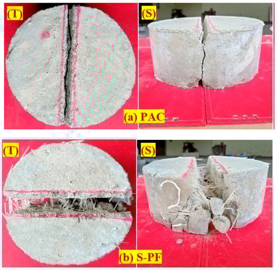
Figure 11.
Failure of specimens.
4.2.6. The Results of the ACI and the Modified Technique Impact Tests
The modified test results from this study are compared to the ACI-544 method testing results from prior work by Prasad and Murali et al. (2021) [] for the same mixtures with similar schemes and dosages of fibre, shown in Figure 12. The modified impact methodology provided higher impact results in Q1 and Q2 compared to ACI-544 method, as shown in Figure 12a,b. Irrespective of the layered concrete, this pattern remained constant across all permutations. Figure 12c illustrates the percentage difference between the modified impact and ACI test methods differed from –11.5% to 90.9% in Q1 and from 8.7% to 78.6% percent in Q2. Due to the fact that the specimens were only subjected to a single contact point, the ACI test yielded a localised impact on a tiny specimen, which resulted in lower values in Q1 and Q2 findings for the specimens. The aggregate, soft material, and fibres region of a compact cylindrical specimen may be subjected to a single point impact, which leads to the accumulation of impact energy in a confined area. Fractures and cracks were spread in a radial direction due to this event, leading to a rapid collapse. The modified impact test, on the other hand, resulted in significantly higher values in impact strength for all FLTSFC specimens. By placing the line-load transmitting steel plate on the top specimen’s surface and striking with a repeated impact, the impact force was distributed across a greater area, resulting in a more uniform distribution of force. A consequence of this decision, the new testing procedure, which included applying single-point impact stress to a soft or hard portion of the fibres, was discarded. This was owing to the fact that the line impact force was delivered across such a large region and did not cause the specimens to collapse soon.
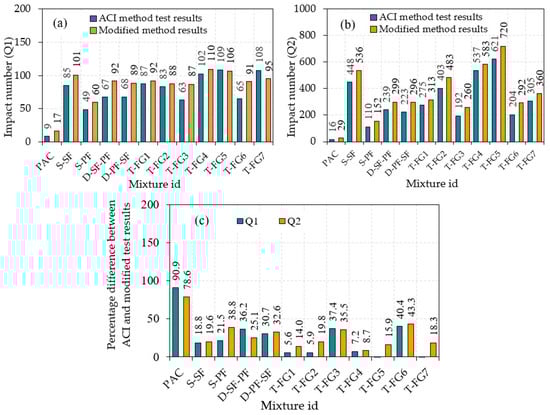
Figure 12.
Impact results comparison between ACI and modified method.
4.2.7. Coefficient of Variance (COV) Comparison
The COV analysis reveals the impact test dispersion. Increasing and decreasing COV levels enhance and reduce the dispersion of impact test results. A smaller COV is always preferred since it indicates a more accurate evaluation. Figure 13 compares the improved impact test COV to the ACI method COV from the earlier study conducted by Prasad and Murali (2021) []. The COV from the ACI test method varied from 32.8% to 50.5% for Q1 and 9.0% to 43.3% for Q2. However, modified impact testing findings showed a lower COV across all twelve combinations, ranging from 9.4% to 16.9% for Q1 and 5.9% to 14.6% for Q2. Compared to the ACI test method’s similar mixtures, the COV value calculated utilizing the modified impact test was reduced and ranged between 57.8% and 78.9% in Q1 and 23.2–75.2% in Q2 shown in Figure 13c. This event demonstrates that adding a line notch specimen that delivers impact using a line-load transmitting steel plate on the top surface instead of a single-point impact enhanced impact strength and decreased the dispersion of results [,,,,,,].
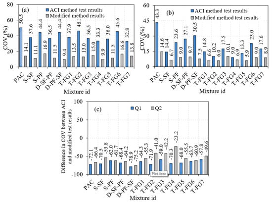
Figure 13.
COV comparison (a) Q1 (b) Q2 and (c) Percentage COV difference in two test methods.
5. Conclusions
In this study, it is proposed that a modified impact test of FLTSFC be performed against low-velocity repeated impacts. A line notch specimen and the line-load transmitting steel plate were introduced to reduce the dispersion of experimental findings. Single, double, and triple layered concrete were prepared using steel and polypropylene fibre to evaluate the impact resistance of mono and hybrid mix designs. According to the comprehensive study, the main results were drawn as follows:
- The S-SF specimen had the highest compressive strength, which increased by 59.6% compared to the PAC specimen. The T-FG2 specimen had the second largest compressive strength increase, with 2.8% SF at the topmost and bottom layers, and 1.6% SF at the intermediate layer, resulting in the second highest compressive strength gain overall. The single-layered specimens exhibited higher compressive strength than the three-layered FLTSFC. The contribution of SF in increasing strength is considerably higher than PF, irrespective of the fibre scheme or number of layers.
- When compared to PAC, the reported Q1 values for the S-SF and S-PF specimens were raised by 5.94 and 5.23 times, respectively. Likewise, the recorded Q2 values increased by about 10.31 and 10.21 times, respectively. This phenomenon is due to the addition of fibres, which increased the matrix’s tensile strength by delivering high tensile stress absorption over cracks via crack bridging.
- Due to the obvious matrix reinforcing impact of fibres, the T-FG group of specimens showed higher Q1 and Q2 records than the PAC specimen, as was anticipated. In Q1 and Q2, significant increases was recorded by about 6.47 and 20.10 times for T-FG4 and 6.4 and 23.2 times for TFG-5, respectively. The top and bottom layers of higher SF dosage receive greater impact stresses due to direct contact with the drop weight and the supporting base plate. Moreover, SF’s crimped and hooked-end structure improved bond strength, including its significantly higher tensile strength than PF.
- The index ductility values of all fibre specimens ranged between 2.53 and 6.79, indicating a greater resistance after cracking. A properly controlled cracking pattern was obtained via the use of notched specimens and transmission plates. The fractures in the notch specimens were initiated and proliferated mostly along the borders of the notches. In contrast, there were many randomly distributed cracks in the samples evaluated according to the ACI 544-2R technique. This regulated activity would simplify the identification of criteria for the acceptance or rejection of results of test specimens according to their cracking pattern, which leads to a reduction in the dispersion of results.
- Compared to the ACI-544 method, the modified impact results were superior. The computed COV values for all twelve mixtures were decreased by 57.8–78.9% in Q1 and by 23.2–75.2% in Q2 compared with the ACI test method. Therefore, the proposed suggestion for the impact test could improve the reliability of results, make them easy to conduct, and contribute to new materials science.
Author Contributions
Conceptualization, N.P. and G.M.; methodology, N.P. and G.M.; software, N.P. and G.M.; validation, N.P. and G.M.; formal analysis, N.P. and G.M.; investigation, N.P. and G.M.; resources, N.P. and G.M.; data curation, N.P. and G.M.; writing—original draft preparation, N.P. and G.M.; writing—review and editing, R.F., S.R.A., N.V., R.F., S.K. and M.A.; visualization, G.M.; supervision, G.M.; project administration, G.M.; funding acquisition, R.F. and N.V. All authors have read and agreed to the published version of the manuscript.
Funding
This research received no external funding.
Institutional Review Board Statement
Not applicable.
Informed Consent Statement
Not applicable.
Data Availability Statement
Not applicable.
Acknowledgments
The authors are grateful to the School of Civil Engineering, SASTRA Deemed to be University, for their support.
Conflicts of Interest
The authors declare no conflict of interest.
Abbreviations
| FLTSFC | Functionally Layered Two-stage Fibrous Concrete |
| FRC | Fibre Reinforced Concrete |
| TSFC | Two-Stage Fibrous Concrete |
| FGC | Functionally Graded Concrete |
| FLFC | Functionally Layered Fibrous concrete |
| PF | Polypropylene Fibre |
| SF | Steel fibre |
| SIFCON | Slurry Infiltrated Fibrous Concrete |
| SP | Superplasticizer |
| Q1 | First crack impact number |
| Q2 | Failure impact number |
| SD | Standard deviation |
| COV | Coefficient of variation |
References
- Abid, S.R.; Ali, S.H.; Murali, G.; Al-Gasham, T.S. A simple suggested approach to reduce the testing time of concrete surface abrasion using ASTM C1138. Case Stud. Constr. Mater. 2021, 15, e00685. [Google Scholar] [CrossRef]
- Murali, G.; Abid, S.R.; Amran, M.; Fediuk, R.; Vatin, N.; Karelina, M. Combined effect of multi-walled carbon nanotubes, steel fibre and glass fibre mesh on novel two-stage expanded clay aggregate concrete against impact loading. Crystals 2021, 11, 720. [Google Scholar] [CrossRef]
- Abid, S.R.; Abdul-Hussein, M.L.; Ayoob, N.S.; Ali, S.H.; Kadhum, A.L. Repeated drop-weight impact tests on self-compacting concrete reinforced with micro-steel fiber. Heliyon 2020, 6, e03198. [Google Scholar] [CrossRef]
- Murali, G.; Abid, S.R.; Abdelgader, H.S.; Amran, Y.H.M.; Shekarchi, M.; Wilde, K. Repeated Projectile Impact Tests on Multi-Layered Fibrous Cementitious Composites. Int. J. Civ. Eng. 2021, 19, 635–651. [Google Scholar] [CrossRef]
- Mohan, K.S.R.; Diviyabharrathi, K.B.; Murali, G. Research on the Development of High Impact Resistant Preplaced Aggregate Fibrous Concrete by the Inclusion of Coarse Aggregates Coated with Asphalt. Arab. J. Sci. Eng. 2021. [Google Scholar] [CrossRef]
- Al-ameri, R.A.; Abid, S.R.; Murali, G.; Ali, S.H.; Özakça, M. Residual repeated impact strength of concrete exposed to elevated temperatures. Crystals 2021, 11, 941. [Google Scholar] [CrossRef]
- Murali, G.; Santhi, A.S.; Mohan Ganesh, G. Empirical relationship between the impact energy and compressive strength for fiber reinforced concrete. J. Sci. Ind. Res. 2014, 73, 469–473. [Google Scholar]
- Murali, G.; Santhi, A.S.; Ganesh, G.M. Impact resistance and strength reliability of fiber-reinforced concrete in bending under drop weight impact load. Int. J. Technol. 2014, 5, 111–120. [Google Scholar] [CrossRef]
- Murali, G.; Santhi, A.S.; Mohan Ganesh, G. Effect of crimped and hooked end steel fibres on the impact resistance of concrete. J. Appl. Sci. Eng. 2014, 17, 259–266. [Google Scholar] [CrossRef]
- Jabir, H.A.; Abid, S.R.; Murali, G.; Ali, S.H.; Klyuev, S.; Fediuk, R.; Vatin, N.; Promakhov, V.; Vasilev, Y. Experimental tests and reliability analysis of the cracking impact resistance of uhpfrc. Fibers 2020, 8, 74. [Google Scholar] [CrossRef]
- Mohamed, N.; Soliman, A.M.; Nehdi, M.L. Full-scale pipes using dry-cast steel fibre-reinforced concrete. Constr. Build. Mater. 2014, 72, 411–422. [Google Scholar] [CrossRef]
- Şahin, Y.; Köksal, F. The influences of matrix and steel fibre tensile strengths on the fracture energy of high-strength concrete. Constr. Build. Mater. 2011, 25, 1801–1806. [Google Scholar] [CrossRef]
- Nataraja, M.C.; Dhang, N.; Gupta, A.P. Statistical variations in impact resistance of steel fiber-reinforced concrete subjected to drop weight test. Cem. Concr. Res. 1999, 29, 989–995. [Google Scholar] [CrossRef]
- Deifalla, A.F.; Zapris, A.G.; Chalioris, C.E. Multivariable regression strength model for steel fiber-reinforced concrete beams under torsion. Materials 2021, 14, 3889. [Google Scholar] [CrossRef]
- Zanuy, C.; Ulzurrun, G.S.D. Impact resisting mechanisms of shear-critical reinforced concrete beams strengthened with high-performance FRC. Appl. Sci. 2020, 10, 3154. [Google Scholar] [CrossRef]
- Kazemi, M.T.; Golsorkhtabar, H.; Beygi, M.H.A.; Gholamitabar, M. Fracture properties of steel fiber reinforced high strength concrete using work of fracture and size effect methods. Constr. Build. Mater. 2017, 142, 482–489. [Google Scholar] [CrossRef]
- Guo, Y.C.; Zhang, J.H.; Chen, G.M.; Xie, Z.H. Compressive behaviour of concrete structures incorporating recycled concrete aggregates, rubber crumb and reinforced with steel fibre, subjected to elevated temperatures. J. Clean. Prod. 2014, 72, 193–203. [Google Scholar] [CrossRef]
- Murali, G.; Vinodha, E. Experimental and Analytical Study of Impact Failure Strength of Steel Hybrid Fibre Reinforced Concrete Subjected to Freezing and Thawing Cycles. Arab. J. Sci. Eng. 2018, 43, 5487–5497. [Google Scholar] [CrossRef]
- Murali, G.; Asrani, N.P.; Ramkumar, V.R.; Siva, A.; Haridharan, M.K. Impact Resistance and Strength Reliability of Novel Two-Stage Fibre-Reinforced Concrete. Arab. J. Sci. Eng. 2019, 44, 4477–4490. [Google Scholar] [CrossRef]
- Ramkumar, V.R.; Murali, G.; Asrani, N.P.; Karthikeyan, K. Development of a novel low carbon cementitious two stage layered fibrous concrete with superior impact strength. J. Build. Eng. 2019, 25, 100841. [Google Scholar] [CrossRef]
- Murali, G.; Poka, L.; Parthiban, K.; Haridharan, M.K.; Siva, A. Impact Response of Novel Fibre-Reinforced Grouted Aggregate Rubberized Concrete. Arab. J. Sci. Eng. 2019, 44, 8451–8463. [Google Scholar] [CrossRef]
- Abirami, T.; Murali, G.; Saravana Raja Mohan, K.; Salaimanimagudam, M.P.; Nagaveni, P.; Bhargavi, P. Multi-layered two stage fibrous composites against low-velocity falling mass and projectile impact. Constr. Build. Mater. 2020, 248, 118631. [Google Scholar] [CrossRef]
- Murali, G.; Ramprasad, K. A feasibility of enhancing the impact strength of novel layered two stage fibrous concrete slabs. Eng. Struct. 2018, 175, 41–49. [Google Scholar] [CrossRef]
- Torelli, G.; Fernández, M.G.; Lees, J.M. Functionally graded concrete: Design objectives, production techniques and analysis methods for layered and continuously graded elements. Constr. Build. Mater. 2020, 242, 118040. [Google Scholar] [CrossRef]
- Sridhar, R.; Prasad, D.R. Damage assessment of functionally graded reinforced concrete beams using hybrid fiber engineered cementitious composites. Structures 2019, 20, 832–847. [Google Scholar] [CrossRef]
- Moghadam, A.S.; Omidinasab, F. Assessment of hybrid FRSC cementitious composite with emphasis on flexural performance of functionally graded slabs. Constr. Build. Mater. 2020, 250, 118904. [Google Scholar] [CrossRef]
- Prasad, N.; Murali, G. Exploring the impact performance of functionally-graded preplaced aggregate concrete incorporating steel and polypropylene fibres. J. Build. Eng. 2021, 35, 102077. [Google Scholar] [CrossRef]
- ACI 544-2R Measurement of Properties of Fiber Reinforced Concrete. Publ. SP Am. Concr. Inst. 1984, 89, 433–439.
- Murali, G.; Karthikeyan, K.; Ramkumar, V.R. Reliability analysis of impact failure energy of fibre reinforced concrete using Weibull distribution. J. Appl. Sci. Eng. 2018, 21, 163–170. [Google Scholar] [CrossRef]
- Murali, G.; Santhi, A.S.; Mohan Ganesh, G. Impact resistance and strength reliability of fiber reinforced concrete using two parameter weibull distribution. J. Eng. Appl. Sci. 2014, 9, 554–559. [Google Scholar]
- Murali, G.; Gayathri, R.; Ramkumar, V.R.; Karthikeyan, K. Two statistical scrutinize of impact strength and strength reliability of steel Fibre-Reinforced Concrete. KSCE J. Civ. Eng. 2018, 22, 257–269. [Google Scholar] [CrossRef]
- Murali, G.; Chandana, V. Weibull reliability analysis of impact resistance on self-compacting concrete reinforced with recycled CFRP pieces. Rev. Rom. Mater. Rom. J. Mater. 2017, 47, 196–203. [Google Scholar]
- Gunasekaran, M.; Thangavel, M.; Nemichandran, N.K.; Ravikumar, I.; Glarance, H.J.; Kothandapani, K. Impact response and strength reliability of green high performance fibre reinforced concrete subjected to freeze-thaw cycles in NaCl solution. Medziagotyra 2017, 23, 384–388. [Google Scholar] [CrossRef][Green Version]
- Gunasekaran, M.; Kothandapani, K.; Kanthamani, M.K.H. Statistical scrutiny of variations in impact strength of green high performance fibre reinforced concrete subjected to drop weight test. Rev. Rom. Mater. Rom. J. Mater. 2018, 48, 214–221. [Google Scholar]
- Haridharan, M.K.; Matheswaran, S.; Murali, G.; Abid, S.R.; Fediuk, R.; Mugahed Amran, Y.H.; Abdelgader, H.S. Impact response of two-layered grouted aggregate fibrous concrete composite under falling mass impact. Constr. Build. Mater. 2020, 263, 120628. [Google Scholar] [CrossRef]
- Prasad, N.; Murali, G.; Vatin, N. Modified falling mass impact test performance on functionally graded two stage aggregate fibrous concrete. Materials 2021, 14, 5833. [Google Scholar] [CrossRef]
- Badr, A.; Ashour, A.F. Modified ACI drop-weight impact test for concrete. ACI Mater. J. 2005, 102, 249–255. [Google Scholar] [CrossRef]
- IS 1489(Part 1): 2015 Portland Pozzolana Cement-Specification; IS 1489 (Part 1) (Third rev.); Bureau of Indian Standards: New Delhi, India, 2015.
- IS 383 Is 383: 2016 Annex-a; Bureau of Indian Standards: New Delhi, India, 2016; pp. 1–14.
- Astm:C939-10 Standard Test Method for Flow of Grout for Preplaced-Aggregate Concrete (Flow Cone Method). ASTM Int. 2010, 4, 9–11. [CrossRef]
- IS 516:2014 Method of Tests for Strength of Concrete; IS 516—1959 (Reaffirmed 2004); Bureau of Indian Standards: New Delhi, India, 2004.
- Nili, M.; Afroughsabet, V. The effects of silica fume and polypropylene fibers on the impact resistance and mechanical properties of concrete. Constr. Build. Mater. 2010, 24, 927–933. [Google Scholar] [CrossRef]
- Yildirim, S.T.; Ekinci, C.E.; Findik, F. Properties of Hybrid Fiber Reinforced Concrete under Repeated Impact Loads. Russ. J. Nondestruct. Test. 2010, 46, 538–546. [Google Scholar] [CrossRef]
- Prasad, N.; Murali, G.; Fediuk, R.; Vatin, N.; Karelina, M. Response of novel functionally-graded prepacked aggregate fibrous concrete against low velocity repeated projectile impacts. Materials 2021, 14, 280. [Google Scholar] [CrossRef]
- Nia, A.A.; Hedayatian, M.; Nili, M.; Sabet, V.A. An experimental and numerical study on how steel and polypropylene fi bers affect the impact resistance in fi ber-reinforced concrete. Int. J. Impact Eng. 2012, 46, 62–73. [Google Scholar] [CrossRef]
- Mastali, M.; Dalvand, A.; Sattarifard, A. The impact resistance and mechanical properties of the reinforced self-compacting concrete incorporating recycled CFRP fi ber with different lengths and dosages. Compos. Part B 2017, 112, 74–92. [Google Scholar] [CrossRef]
- Rithanyaa, R.; Murali, G.; Salaimanimagudam, M.P.; Fediuk, R.; Abdelgader, H.S.; Siva, A. Impact response of novel layered two stage fibrous composite slabs with different support type. Structures 2021, 29, 1–13. [Google Scholar] [CrossRef]
- Murali, G.; Abid, S.R.; Karthikeyan, K.; Haridharan, M.K.; Amran, M.; Siva, A. Low-velocity impact response of novel prepacked expanded clay aggregate fibrous concrete produced with carbon nano tube, glass fiber mesh and steel fiber. Constr. Build. Mater. 2021, 284, 122749. [Google Scholar] [CrossRef]
- Li, Q.; Zhao, X.; Xu, S.; Leung, C.K.Y.; Wang, B. Multiple Impact Resistance of Hybrid Fiber Ultrahigh Toughness Cementitious Composites with Different Degrees of Initial Damage. J. Mater. Civ. Eng. 2019, 31, 04018368. [Google Scholar] [CrossRef]
- Fu, Q.; Niu, D.; Li, D.; Wang, Y.; Zhang, J.; Huang, D. Impact characterization and modelling of basalt–polypropylene fibre-reinforced concrete containing mineral admixtures. Cem. Concr. Compos. 2018, 93, 246–259. [Google Scholar] [CrossRef]
- Ghernouti, Y.; Rabehi, B.; Bouziani, T.; Ghezraoui, H.; Makhloufi, A. Fresh and hardened properties of self-compacting concrete containing plastic bag waste fibers (WFSCC). Constr. Build. Mater. 2015, 82, 89–100. [Google Scholar] [CrossRef]
- Mastali, M.; Ghasemi Naghibdehi, M.; Naghipour, M.; Rabiee, S.M. Experimental assessment of functionally graded reinforced concrete (FGRC) slabs under drop weight and projectile impacts. Constr. Build. Mater. 2015, 95, 296–311. [Google Scholar] [CrossRef]
- Ramkumar, V.R.; Komarasamy, C.; Gunasekaran, M. Impact resistance of fibre reinforced concrete containing lime sludge based composite cements. J. Struct. Eng. 2018, 44, 649–662. [Google Scholar]
- Asrani, N.P.; Murali, G.; Parthiban, K.; Surya, K.; Prakash, A.; Rathika, K.; Chandru, U. A feasibility of enhancing the impact resistance of hybrid fibrous geopolymer composites: Experiments and modelling. Constr. Build. Mater. 2019, 203, 56–68. [Google Scholar] [CrossRef]
- Mo, K.H.; Yap, S.P.; Alengaram, U.J.; Jumaat, M.Z.; Bu, C.H. Impact resistance of hybrid fibre-reinforced oil palm shell concrete. Constr. Build. Mater. 2014, 50, 499–507. [Google Scholar] [CrossRef]
- Manohar, T.; Suribabu, C.R.; Murali, G.; Salaimanimagudam, M.P. A novel steel-PAFRC composite fender for bridge pier protection under low velocity vessel impacts. Structures 2020, 26, 765–777. [Google Scholar] [CrossRef]
- Salaimanimagudam, M.P.; Suribabu, C.R.; Murali, G.; Abid, S.R. Impact response of hammerhead pier fibrous concrete beams designed with topology optimization. Period. Polytech. Civ. Eng. 2020, 64, 1244–1258. [Google Scholar] [CrossRef]
- Abirami, T.; Loganaganandan, M.; Murali, G.; Fediuk, R.; Vickhram Sreekrishna, R.; Vignesh, T.; Januppriya, G.; Karthikeyan, K. Experimental research on impact response of novel steel fibrous concretes under falling mass impact. Constr. Build. Mater. 2019, 222, 447–457. [Google Scholar] [CrossRef]
- Ramakrishnan, K.; Depak, S.R.; Hariharan, K.R.; Abid, S.R.; Murali, G.; Cecchin, D.; Fediuk, R.; Mugahed Amran, Y.H.; Abdelgader, H.S.; Khatib, J.M. Standard and modified falling mass impact tests on preplaced aggregate fibrous concrete and slurry infiltrated fibrous concrete. Constr. Build. Mater. 2021, 298, 123857. [Google Scholar] [CrossRef]
- Abid, S.R.; Abdul Hussein, M.L.; Ali, S.H.; Kazem, A.F. Suggested modified testing techniques to the ACI 544-R repeated drop-weight impact test. Constr. Build. Mater. 2020, 244, 118321. [Google Scholar] [CrossRef]
- Prasad, N.; Murali, G. Research on flexure and impact performance of functionally-graded two-stage fibrous concrete beams of different sizes. Constr. Build. Mater. 2021, 288, 123138. [Google Scholar] [CrossRef]
- Elistratkin, M.Y.; Lesovik, V.S.; Zagorodnjuk, L.H.; Pospelova, E.A.; Shatalova, S.V. New point of view on materials development. IOP Conf. Ser. Mater. Sci. Eng. 2018, 327, 32020. [Google Scholar] [CrossRef]
- Klyuyev, S.V.; Guryanov, Y.V. External reinforcing of fiber concrete constructions by carbon fiber tapes. Mag. Civ. Eng. 2013, 36, 21–26. [Google Scholar] [CrossRef]
- Begich, Y.E.; Klyuev, S.V.; Jos, V.A.; Cherkashin, A.V. Fine-grained concrete with various types of fibers. Mag. Civ. Eng. 2020, 97. [Google Scholar] [CrossRef]
- Klyuyev, A.V.; Sopin, D.M.; Netrebenko, A.V.; Kazlitin, S.A. Heavy loaded floors based on fine-grained fiber concrete. Mag. Civ. Eng. 2013, 38, 7–14. [Google Scholar] [CrossRef]
- Klyuev, S.V.; Bratanovskiy, S.N.; Trukhanov, S.V.; Manukyan, H.A. Strengthening of concrete structures with composite based on carbon fiber. J. Comput. Theor. Nanosci. 2019, 16, 2810–2814. [Google Scholar] [CrossRef]
- Lesovik, R.V.; Klyuyev, S.V.; Klyuyev, A.V.; Tolbatov, A.A.; Durachenko, A.V. The Development of textile fine-grained fiber concrete using technogenic raw materials. Res. J. Appl. Sci. 2015, 10, 701–706. [Google Scholar]
- Lesovik, R.V.; Klyuyev, S.V.; Klyuyev, A.V.; Netrebenko, A.V.; Durachenko, A.V. High-strength fiber-reinforced concrete containing technogenic raw materials and composite binders with use of nanodispersed powder. Res. J. Appl. Sci. 2014, 9, 1153–1157. [Google Scholar]
Publisher’s Note: MDPI stays neutral with regard to jurisdictional claims in published maps and institutional affiliations. |
© 2021 by the authors. Licensee MDPI, Basel, Switzerland. This article is an open access article distributed under the terms and conditions of the Creative Commons Attribution (CC BY) license (https://creativecommons.org/licenses/by/4.0/).