Abstract
This study examines in situ induction-heating thermal field assistance during laser cladding of Stellite 6 on 17-4PH stainless steel. Single-layer, multi-track coatings (~2.3 mm) were produced at induction powers of 0, 300, 600, and 900 W while keeping laser parameters constant. Surface morphology, phase constituents, and microstructures were characterized by LSCM, OM, XRD, SEM, EDS, and EBSD, and nanoscale features were probed by TEM for the 600 W condition; microhardness and coating-only tensile properties were evaluated. Thermal assistance improved surface finish (minimum Sa = 16.67 μm at 600 W) and suppressed hot cracking. XRD/EBSD revealed a γ-Co matrix with interdendritic carbides and an increased ε-Co fraction under thermal assistance; TEM further showed stacking-fault lamellae and a distinct FCC/HCP interface, supporting a fault-assisted, diffusionless γ → ε transformation. Increasing induction power coarsened the microstructure (larger DE and SDAS), decreasing hardness from 537.1 to 461.5 HV0.1 and lowering yield/ultimate strengths from 1046 MPa and 1512 MPa to 849 MPa and 1423 MPa, while elongation increased from 4.37% to 6.27%. Considering crack-free valve hardfacing with acceptable strength loss and improved ductility, 600 W provides the best overall performance.
1. Introduction
17-4PH martensitic precipitation-hardening stainless steel is a common structural material for nuclear valves. However, its surface is prone to wear, fretting fatigue, and stress corrosion failure during high-temperature service, affecting sealing performance and lifespan [1,2]. Therefore, Stellite 6 cobalt-based alloy, known for its high hardness, excellent corrosion resistance, and high-temperature oxidation resistance [3], is often used as a wear-resistant coating for surface strengthening. Traditional coating processes like plasma arc surfacing and brazing suffer from excessive heat input and high dilution rates, which can lead to deviations from the designed coating composition, grain coarsening, and precipitate growth, consequently affecting wear resistance and crack susceptibility [4,5,6]. Laser cladding technology offers an effective alternative, as its high-energy beam characteristics enable metallurgical bonding with low dilution rates (<10%) and form high-hardness equiaxed crystal regions on the coating surface through rapid cooling [7]. Researchers domestically and internationally have conducted series of studies on cladding cobalt-based alloys onto 17-4PH stainless steel. Qin et al. from the Institute of Metal Research, Chinese Academy of Sciences [8], prepared cobalt-based alloy laser cladding coatings on 17-4PH stainless steel and studied their cavitation erosion performance. The results showed excellent cavitation erosion resistance of the cobalt-based alloy, and the work-hardened layer generated on the coating surface after cavitation further increased the material hardness. Sun et al. from Zhejiang University of Technology [9] used laser cladding technology to prepare Stellite 6 coatings on 17-4PH stainless steel and studied their service performance, indicating good cavitation erosion resistance. Ren et al. from Shanghai Jiao Tong University [10] prepared Stellite 6 alloy coatings on 17-4PH stainless steel and conducted corrosion and fatigue tests. The results showed that the electrochemical corrosion resistance of the Stellite 6 alloy coating was about 10 times that of the substrate, and its fatigue limit reached 380 MPa.
However, the excessive cooling rate during laser cladding can introduce steep thermal gradients and strain incompatibility during cooling, which increases the susceptibility to coating cracking. Previous studies have reported that introducing external heat input can moderate the thermal gradient and the associated strain incompatibility during deposition, thereby suppressing cracks and related defects [11]. Lu et al. [12] used directed energy deposition (DED) technology combined with substrate preheating to prepare Ti6Al4V and analyzed the effect of substrate preheating on residual stress using 3D thermomechanical coupling, showing an 80.2% reduction in residual stress at a preheating temperature of 700 °C. Baek et al. [13] used resistance wire as a thermal assistance device and preheated the substrate to 200–300 °C during the preparation of M4 tool steel using L-DED technology. The results showed that thermal field assistance effectively reduced residual stress and inhibited crack growth; however, excessively high assistance temperature (≥500 °C) caused grain coarsening and carbide growth in the sample structure, reducing strength and toughness.
Compared to resistance-wire preheating—which can cause undesirable substrate overheating due to limited localized control—in situ heating processes allow for more precise localization of heat input, effectively protecting the substrate’s microstructure and properties. Dalaee et al. [14] used an induction coil as a thermal assistance device and prepared In625 coatings using L-DED technology. The results showed that electromagnetic induction preheating effectively improved the cladding-layer preparation efficiency, offering higher heating temperatures and a more uniform thermal field. Fan et al. [15] used finite element simulation to study the effect of synchronous induction heating on the cladding process, showing that synchronous heating reduced thermal stress during cladding by about 80%, and the maximum stress area shifted from the bottom of the deposition to the middle of the substrate.
In summary, synchronous heating with induction coils, as a typical thermal field assistance technique for laser cladding, holds great potential. However, systematic research on its impact mechanism on the microstructure and mechanical properties of cladding layers is scarce. Therefore, this paper takes the cladding of Stellite 6 coating on 17-4PH stainless steel surface as an example, uses an in situ heating induction coil device during the cladding process, and studies the effects of different thermal field assistance induction heating powers on the coating’s macroscopic morphology, phase composition, microstructure, and mechanical properties, aiming to provide a reference for expanding the application of thermal field assistance in laser cladding.
2. Materials and Methods
2.1. Materials
17-4PH stainless steel was used as the substrate material, with dimensions of 250 mm × 150 mm × 70 mm. The cladding raw powder was spherical Stellite 6 with a particle size range of 53–150 μm (Avimetal AM Tech Co., Ltd., Beijing, China). Its microscopic morphology, shown in Figure 1a, indicates good sphericity and flowability. The particle size distribution, shown in Figure 1b, has a median particle size (D50) of approximately 108.97 μm. The powder was gas-atomized, which ensured uniform particle size distribution. Table 1 shows the chemical composition of the Stellite 6 alloy powder.
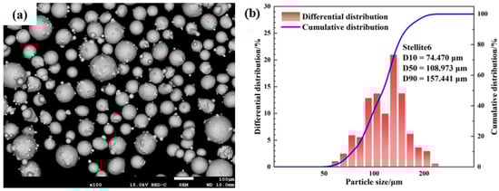
Figure 1.
(a) SEM image of the Stellite 6 raw powder; (b) particle size distribution of Stellite 6 raw powder.

Table 1.
Chemical composition of Stellite 6 raw powder.
2.2. Experimental Procedures
Before the experiment, the oxide scale and other impurities on the surface of the 17-4PH substrate were removed with an angle grinder, and the surface oil stains were cleaned with anhydrous ethanol. The substrate was then placed in an 80 °C oven for 2 h. The powder was dried in a 120 °C vacuum oven for 1 h before the experiment. The laser cladding system used in this paper consisted of a 6 kW fiber laser (wavelength 1080 nm), a six-axis industrial robot, and a powder-feed gas system. Argon gas with a purity of 99.99% was used as the shielding gas and powder-feed gas. During the experiment, the thermal field assistance in situ heating device shown in Figure 2 was used for heating. Coaxial powder feeding was adopted. The cladding strategy consisted of a multi-track, single-layer deposition pattern, with a back-and-forth scanning pattern. Adjacent tracks overlapped by 73%. The scanning direction alternated between successive tracks. A schematic of the scanning pattern is shown in Figure 2c.
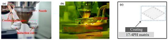
Figure 2.
Thermal-field-assisted in situ heating device (a) assembly diagram; (b) operational diagram; (c) cladding pattern.
The processing parameters listed in Table 2 were selected based on preliminary trials to obtain a stable single-layer multi-track coating with continuous tracks, good surface continuity, and no obvious lack of fusion under the given powder size range (53–150 μm). In this study, the laser power, scanning speed, powder feeding rate, and gas flow rates were kept constant to minimize confounding effects from changes in energy input and powder delivery. The overlap rate (73%) was chosen to ensure sufficient remelting between adjacent tracks and to achieve a relatively flat surface morphology for subsequent microstructural and mechanical characterization. The induction heating power was the only intentionally varied parameter (0, 300, 600, and 900 W) to isolate and quantify the influence of thermal field assistance on coating formation, microstructure evolution, and mechanical response. The four cladding samples were named according to their corresponding thermal assistance power. Only a single layer of Stellite 6 coating was deposited, with an average coating thickness of approximately 2.3 mm. This thickness was consistent across all the cladded samples.
Table 2.
Laser cladding process parameters.
This paper conducted macro- and micro-level microstructure characterization of coatings prepared with thermal assistance technology. A laser scanning confocal microscope (LSCM, OLS5000, Olympus, Tokyo, Japan) was used to observe the macroscopic surface 3D morphology of the laser cladding samples and obtain the average surface roughness Sa. The detection range was about 2.5 mm × 2.5 mm, and the roughness was measured at three random locations on each sample to ensure accuracy. An optical microscope (OM, Axiovert 5, Carl Zeiss, Oberkochen, Germany) was used to examine the macroscopic cross-sectional morphology of the cladding coatings. An X-ray diffractometer (XRD, D8 Advance, Bruker, Billerica, MA, USA) was used to characterize the phase types of the cladding coatings, with a scanning voltage and current of 40 kV and 30 mA, respectively, and a diffraction angle range and step size of 20–90° and 0.02°, respectively. A scanning electron microscope (SEM, Sigma 300, Carl Zeiss, Oberkochen, Germany) equipped with an X-ray spectrometer (EDS) and an electron backscatter diffraction (EBSD) probe was used to characterize the microstructure, microscopic element distribution, dislocation density, and low/high-angle grain-boundary content of the metallographic samples.
Cobalt-based alloy Stellite 6 has high hardness and excellent wear and corrosion resistance [3], hence its use as a strengthening material on stainless steel surfaces. This paper used a micro-Vickers hardness tester (FM-700, FUTURE-TECH, Kawasaki, Japan) to measure the microhardness of the surface and cross-section of the cladding coatings. The test load was 100 gf, and the dwell time was 15 s. For surface hardness testing, 10 random points were selected, and the average value was taken. For cross-sectional hardness testing, one sample from each of the three parallel samples was randomly selected.
Tensile tests were conducted by a universal mechanical testing machine (Instron 8802, Instron, Norwood, MA, USA) in accordance with GB/T 228.1-2021 [16] (method of tensile test at room temperature). The tensile specimens were machined entirely from the laser-cladded Stellite 6 coating, without including the 17-4PH substrate material, as illustrated in Figure 3a,b. The gauge section consisted solely of the deposited coating, with a thickness of 1 mm, ensuring that the measured tensile response was dominated by the coating material. For each sample, three parallel specimens were used for tensile testing to ensure reproducibility of the results. Tests were conducted at a fixed strain rate of 1 mm/min. The specimens were properly aligned in the testing machine, and the tensile load was applied while the displacement was monitored using a laser extensometer. The stress–strain curves were recorded, and the yield strength, ultimate tensile strength (UTS), and elongation at break were determined from these curves. After the test, the tensile fracture surfaces were examined using scanning electron microscopy (SEM, Sigma 300, Carl Zeiss, Oberkochen, Germany) to analyze the fracture mechanism.
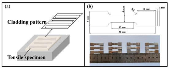
Figure 3.
Schematic of tensile test specimen. (a) Schematic of sample extraction; (b) schematic of sample dimensions.
3. Results and Discussion
3.1. Macrostructure and Morphology
Figure 4 shows the surface 3D morphology and surface roughness Sa data of laser cladding samples under different thermal assistance powers. From Figure 4a–d, it can be seen that the laser cladding sample surfaces under the process parameters with a 73% overlap rate are relatively flat, with small protrusions present on all four sample surfaces. This is because during laser cladding, some metal powder is not fully heated and melted, remaining on the sample surface to form the small protrusions shown. To scientifically evaluate the impact of the thermal assistance process on the surface morphology of laser cladding samples, this paper introduces the average surface roughness (Sa) as a measurement indicator. As the thermal assistance power increases, the protrusions on the laser cladding sample surface first decrease and then increase. Combined with Figure 4e, the average surface roughness (Sa) of the samples decreases from 35.73 µm to 16.67 µm and then increases to 25.59 µm. This is because when using the thermal assistance process for in situ heating of the laser cladding coating, as the thermal assistance power increases, the unmelted powder on the surface gradually melts, causing the sample surface roughness to gradually decrease. However, when the thermal assistance power is too high, it causes local overmelting on the cladding-layer surface, increasing the radial surface tension gradient of the molten metal. This gradient drives the melt to flow from the center to the periphery, forming an undulating wrinkled structure upon solidification, causing the surface roughness to increase again [17].
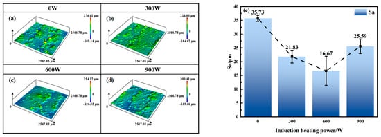
Figure 4.
Surface morphology and roughness of laser-cladded Stellite 6 coating. (a) 0 W; (b) 300 W; (c) 600 W; (d) 900 W; (e) roughness.
The cross-sectional microstructure of the polished samples was observed using an optical microscope, as shown in Figure 5. The interface between the four coating samples and the substrate is relatively flat. Among them, the 0 W sample (without thermal field assistance) contains many cracks in its structure, and the crack propagation path is relatively rugged. In contrast, no cracks were found in the three samples (300 W, 600 W, 900 W) prepared using the thermal assistance process. The above results indicate that the thermal field assistance in situ heating process can effectively improve the surface and cross-sectional structure of the coating. When the induction heating power is 600 W, the sample has the lowest surface roughness.
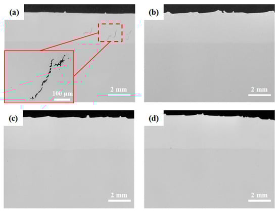
Figure 5.
Cross-sectional morphology of laser-cladded Stellite 6 coating obtained by optical microscopy (OM). (a) 0 W, (b) 300 W; (c) 600 W; (d) 900 W.
3.2. Phase Composition
X-ray diffraction analysis was performed on the laser cladding coating samples, and the results are shown in Figure 6. From Figure 6a, it can be seen that the main diffraction peaks in the XRD patterns of the four Stellite 6 coating groups are from γ-Co, M23C6, and M7C3. It is worth noting that an allotropic transformation of Co occurred in the laser-clad samples: the Co element exists as face-centered cubic (FCC) γ-Co above 360 °C and typically as hexagonal close-packed (HCP) ε-Co at room temperature [18]. Owing to the rapid thermal cycle during laser cladding, a considerable fraction of γ-Co can be retained at room temperature [19], and the solid solution of alloying elements (e.g., Ni) further stabilizes the FCC γ-Co phase [20], ultimately resulting in a large amount of γ-Co being present at room temperature.
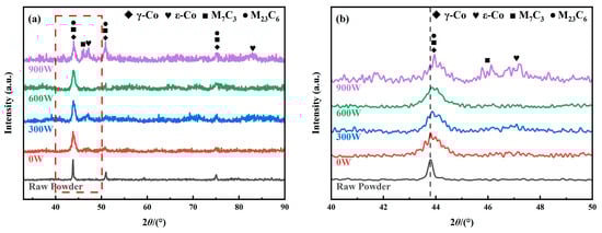
Figure 6.
XRD diffraction patterns of laser-cladded Stellite 6 coating. (a) Full pattern; (b) enlarged view.
Notably, in the thermally assisted samples, additional ε-Co diffraction peaks appear near ~47°, indicating the presence of ε-Co. Figure 6b further shows a gradual shift in the γ-Co peak position with increasing thermal assistance power, suggesting a systematic variation in phase constitution. The spatial distribution and quantitative phase fractions under different induction heating powers are further analyzed by EBSD.
3.3. Microstructure
An analysis of the cracking cause in the 0 W sample was conducted, and the results are shown in Figure 7. The SEM images and the IPF map indicate that the grains on the two sides of the crack exhibit different orientations, and the crack mainly propagates along grain boundaries with a tortuous path. These features are morphologically consistent with hot cracking. From the KAM and grain-boundary maps, pronounced local lattice distortion and a high fraction of low-angle grain boundaries are observed in the cracked region (marked by the white dashed circle), indicating a high dislocation content and strain accommodation. Scholars [21,22,23] have analyzed the causes of hot cracks in cobalt-based alloy coatings. The excessive cooling rate can generate steep thermal gradients and pronounced strain incompatibility during solidification and cooling, increasing the cracking tendency of the coating. When the residual stress exceeds the grain-boundary binding strength, intergranular cracks occur. Accordingly, process measures such as substrate preheating and reduced cooling severity can moderate the thermal gradient and strain incompatibility, thereby lowering the cracking susceptibility [24].
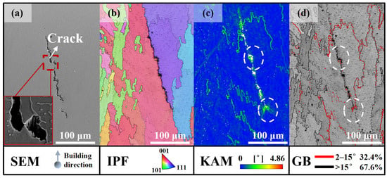
Figure 7.
EBSD analysis of cracks in 0 W sample: (a) SEM image; (b) IPF image; (c) KAM map; (d) high- and low-angle grain-boundary distribution image. The white dashed circle marks the presumed crack initiation site, where elevated KAM values and a high fraction of low-angle grain boundaries indicate strong local lattice distortion.
To further clarify the effect of the thermal assistance process on the Stellite 6 coating structure and its mechanism for eliminating cracks, the microstructure of the 600 W sample was characterized using SEM, EDS, and EBSD. Figure 8 shows SEM images of the cross-sectional microstructure of the 600 W sample. In Figure 8a, the black box indicates equiaxed crystals, the red box indicates dendrites, the yellow box indicates columnar crystals, the blue box indicates cellular crystals, and the white box indicates planar crystals. Figure 8b–d show the structural morphology from the top to the bottom region of the coating, revealing a transition pattern of “equiaxed crystals–dendrites–columnar crystals–planar crystals” from top to bottom, similar to the structure of traditional laser-cladded Stellite 6 coatings without thermal field assistance [25,26]. The differences in structural morphology in different areas of the cladding coating are mainly due to inconsistent cooling rates at different positions of the coating. Research shows that the morphology of laser cladding coatings is mainly influenced by two parameters: the temperature gradient G and the cooling rate R [27,28]. The cooling rate R is fastest in the top region of the coating. This area is closer to the cladding head, and the temperature gradient G is smaller, making it prone to fine equiaxed crystals and dendrites. The cooling rate gradually slows down in the middle region of the coating, and the temperature gradient gradually increases. The middle part of the coating mainly consists of dendritic crystals. The cooling rate R is slowest in the bottom region of the coating. The position in contact with the substrate has the largest temperature gradient G, leading to the appearance of cellular crystals and planar crystals in the structure.
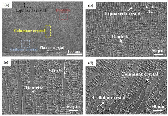
Figure 8.
SEM image of laser-cladded Stellite 6 coating (600 W sample): (a) overview; (b) top; (c) middle; (d) bottom.
After introducing thermal field assistance, the morphological morphology of the Stellite 6 cladding coating remained basically consistent, but the structural size changed. Using the method described in reference [29], Image J image processing software was used to statistically determine the equiaxed grain size (DE) and secondary dendrite arm spacing (SDAS) at the top of the four coating samples. The results are shown in Figure 9. As the thermal assistance power increased from 0 W to 900 W, DE increased from 3.05 µm to 4.30 µm, and SDAS increased from 2.15 µm to 2.98 µm. DE and SDAS can effectively reflect the influence of heat dissipation on the growth of the Stellite 6 coating structure. The above results indicate that under the action of the in situ induction-heating thermal field assistance device, the heat accumulation effect intensifies and the coating cooling rate slows down, causing the growth of structures such as equiaxed crystals and dendrites to varying degrees.
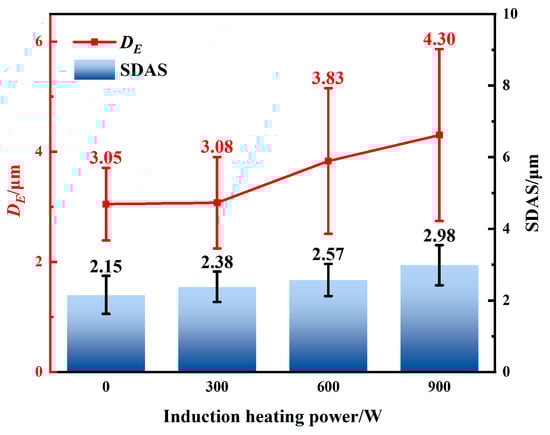
Figure 9.
Equiaxed grain size (DE) and secondary dendrite arm spacing (SDAS) in the mid-region of laser-cladded Stellite 6 coating.
To further characterize the distribution of various elements in the thermal-field-assisted laser cladding Stellite 6 coating, EDS spectroscopy was used to characterize the structure in the middle of the coating. The results are shown in Figure 10. Simultaneously, EDS point-scan analysis was performed on the two structures at higher magnification, and the results are shown in Table 3. From the EDS area-scan results, the coating structure consists of two parts: a blocky dark-gray structure and a reticular light-gray structure. The dark-gray structure is rich in Co element, while the light-gray structure contains large amounts of C, Cr, and W elements. Combined with the XRD analysis results of the cladding coating, the dark-gray structure is the γ-Co solid solution, and the light-gray structure at the grain boundaries is mainly composed of M23C6 and M7C3 carbides [3].

Figure 10.
Thermal-field-assisted laser-cladded Stellite 6 coating (600 W sample): (a) EDS mapping; (b) EDS pointing.
Figure 10.
Thermal-field-assisted laser-cladded Stellite 6 coating (600 W sample): (a) EDS mapping; (b) EDS pointing.

Table 3.
Elemental composition at different positions in Stellite 6 (600 W sample) microstructure (%, atomic fraction).
Table 3.
Elemental composition at different positions in Stellite 6 (600 W sample) microstructure (%, atomic fraction).
| Point | C | Cr | Co | Fe | O | W | Ni | Mo |
|---|---|---|---|---|---|---|---|---|
| 1 | 17 | 24 | 50.4 | 4.3 | 0.6 | 1.2 | 2.4 | 0.2 |
| 2 | 15.9 | 23.8 | 51.5 | 4.3 | 0.5 | 1.1 | 2.6 | 0.2 |
| 3 | 32.9 | 31.1 | 29.3 | 2.4 | 1.0 | 1.6 | 1.3 | 0.5 |
| 4 | 37.9 | 30.7 | 25.2 | 2.2 | 1.1 | 1.3 | 1.2 | 0.4 |
Since the coating structure changed noticeably after introducing thermal field assistance, EBSD was used to further analyze the grain orientation, lattice distortion degree, and low/high-angle grain-boundary ratio in the sample’s microstructure. The specific results are shown in Figure 11. From Figure 11(a1),(b1), it can be seen that after applying 600 W thermal field assistance, the average grain size of the coating increased from 17.37 µm to 20.77 µm. This is mainly because the thermal field assistance slowed down the coating’s heat dissipation rate, increasing the growth time of grains in the structure. KAM (Kernel Average Misorientation) represents the average orientation difference between a point and its adjacent points within a grain. KAM reflects local lattice curvature and is widely used as an indirect indicator of local plastic strain/lattice distortion (closely related to geometrically necessary dislocations), rather than a direct measurement of residual stress. The geometrically necessary dislocation (GND) density (ρGND) of the two samples was calculated using Equation (1) [30]. The calculation results show that the ρGND for the 0 W and 600 W samples are 7.3 × 10¹⁴/m2 and 4.4 × 10¹⁴/m2, respectively. Combined with Figure 11(a2),(b2), thermal field assistance promotes recovery during cooling, reducing local lattice distortion/dislocation density and leading to more uniform strain accommodation.
where θm is the average misorientation angle, μ is the scan step size (1 µm), and b is the Burgers vector magnitude.
ρGND = 2θm/μb
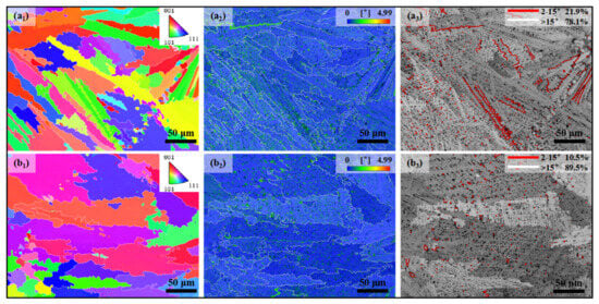
Figure 11.
EBSD maps for the 0 W and 600 W laser-cladded Stellite 6 coatings: (a1,b1) IPF maps; (a2,b2) KAM maps; (a3,b3) the distribution of LAGBs (2–15°) and HAGBs (>15°).
Grain boundaries between adjacent grains with a misorientation angle less than 15° are generally defined as low-angle grain boundaries (LAGBs). From the observation and analysis of Figure 11(a3),(b3), after applying 600 W thermal field assistance, the content of low-angle grain boundaries (LAGBs, 2–15°) in the coating structure decreased from 21.9% to 10.5%, consistent with the trend in dislocation density change. Liu [31] et al. believe this phenomenon is mainly due to the reduction in LAGB content, which decreases the distortion and entanglement experienced by dislocations during movement. These phenomena all indicate that the thermal field assistance process can effectively reduce the risk of coating cracking.
The phase content in the middle of the samples under different induction heating powers was quantified by EBSD (Figure 12 and Table 4). As shown in Figure 12, γ-Co (FCC) dominates the matrix, whereas ε-Co (HCP) and carbides are mainly located in the interdendritic regions. With increasing induction heating power, both the ε-Co fraction and the carbide fraction increase (Table 4), consistent with the XRD results. This trend indicates that thermal field assistance modifies the thermal history during deposition, leading to a reduced effective cooling rate and prolonged thermal exposure, which facilitate the diffusionless γ → ε transformation in Co-based alloys.
Beyond cooling conditions, the γ → ε transformation may also be influenced by the stacking-fault energy (SFE) and the associated stacking-fault density. Since SFE in Co-based alloys is composition-dependent, local solute partitioning and defect-level segregation (e.g., Suzuki segregation) can modify the propensity for stacking-fault formation and thereby affect the nucleation of HCP stacking/ε-Co. In addition, carbide precipitation coupled with solute redistribution in interdendritic regions can further perturb the local chemistry and defect structure, contributing to variations in ε-Co fraction [32]. Meanwhile, the increased thermal exposure promotes solute redistribution and carbide precipitation/coarsening, thereby increasing the carbide fraction and altering the local matrix composition; these effects jointly influence the γ/ε balance. Similar interdendritic ε-Co in laser-cladded Stellite 6 has also been reported by Liu et al. [31], and the role of thermal history on carbide evolution has been discussed in Refs. [33,34].
Notably, although the carbide fraction increases with induction heating power, the moderated thermal gradient and improved strain accommodation under thermal assistance reduce the susceptibility to hot cracking, indicating that crack suppression is governed primarily by the thermomechanical conditions during solidification/cooling rather than carbide fraction alone. A quantitative assessment of carbide size/continuity and chemistry at grain boundaries requires dedicated high-resolution analyses (e.g., EPMA/TEM) and will be addressed in future work.

Figure 12.
Phase distribution maps of the laser-cladded Stellite 6 coatings. (a) 0 W; (b) 300 W; (c) 600 W; (d) 900 W.
Figure 12.
Phase distribution maps of the laser-cladded Stellite 6 coatings. (a) 0 W; (b) 300 W; (c) 600 W; (d) 900 W.

Table 4.
Phase composition and area fraction of coatings under different induction heating power/%. Note: Phase fractions were quantified from the middle region of each sample using EBSD maps of 22.75 × 17 μm2, and the reported values represent area fractions.
Table 4.
Phase composition and area fraction of coatings under different induction heating power/%. Note: Phase fractions were quantified from the middle region of each sample using EBSD maps of 22.75 × 17 μm2, and the reported values represent area fractions.
| Samples | γ-Co | ε-Co | Cr23C6 | Cr7C3 | W2C | Zero Solution |
|---|---|---|---|---|---|---|
| 0 W | 94.91 | 0.19 | 0.71 | 0.37 | 0.38 | 3.44 |
| 300 W | 94.33 | 0.23 | 0.75 | 1.00 | 0.81 | 2.88 |
| 600 W | 93.75 | 0.29 | 0.82 | 1.42 | 0.60 | 3.12 |
| 900 W | 91.07 | 0.62 | 2.31 | 1.45 | 1.12 | 3.43 |
Figure 13 presents TEM/STEM characterization of the coating prepared at 600 W induction heating power, providing direct nanoscale evidence for ε-Co formation. In the HAADF image (Figure 13a), stacking faults appear as bright lamellar bands in the γ-Co matrix, attributed to the strong Z-contrast sensitivity and local structural contrast; a representative stacking fault is highlighted by the white arrow. The corresponding HRTEM image (Figure 13b) taken from the region marked by the yellow box in Figure 13a reveals a distinct FCC-Co/HCP-Co interface, with SAED patterns confirming the coexistence of both crystal structures. The measured lattice spacings (d ≈ 1.925 Å for FCC and d ≈ 1.878 Å for HCP) further corroborate the phase identification. Together, these observations indicate a fault-assisted pathway for ε-Co formation, consistent with reports that the FCC → HCP transformation in Co-based alloys proceeds diffusionlessly and is closely linked to stacking-fault structures and their energetics [32]. Quantitative chemical profiling across the FCC/HCP interface and carbide-adjacent regions requires dedicated STEM-EDS/EELS analyses, which will be addressed in future work.
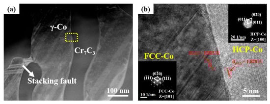
Figure 13.
TEM phase identification of 600 W sample: (a) high-angle annular dark field image (HAADF); (b) high-resolution interface image (HRTEM).
3.4. Mechanical Properties
Figure 14 shows the average micro-Vickers hardness values of the four samples. The surface hardness of the coating gradually decreases with increasing thermal assistance power. This trend is consistent with the Hall–Petch-type strengthening concept, as shown in Equation (2), where smaller characteristic microstructural length scales generally lead to higher strength [35], and hardness is often approximately proportional to strength; therefore, the increase in the average equiaxed grain size (DE) and the secondary dendrite arm spacing (SDAS) on the coating surface from 0 to 900 W is expected to reduce the coating hardness. From the cross-sectional hardness profiles, the hardness gradually decreases with increasing distance from the top surface and drops sharply at ~2.25–2.5 mm, corresponding to the coating/substrate interface. Notably, the coating and substrate hardness values of the 900 W sample are lower than those of the other samples, which is attributed to excessive thermal assistance causing more pronounced coarsening and softening in both the coating and the heat-affected substrate region.
where σy is the yield strength of the sample (MPa); σ0 is the single-crystal yield strength (MPa); K is a constant; d is the average grain size of the sample (nm).
σy = σ0 + Kd−1/2
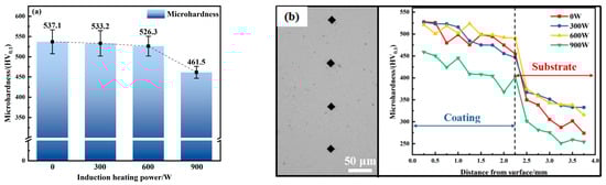
Figure 14.
Micro-Vickers hardness of thermal-field-assisted laser-cladded Stellite 6 coating: (a) surface hardness; (b) cross-sectional hardness.
The tensile tests were performed on specimens composed solely of the Stellite 6 coating. Therefore, the reported mechanical properties reflect the behavior of the coating material under uniaxial tension, with minimal influence from the substrate due to the removal of the base material during specimen extraction. The stress–strain curves of the four samples are shown in Figure 15, and the tensile test results are shown in Table 5. As shown in the figure, the curves of all four samples include an elastic deformation stage and uniform plastic deformation stage. No yield plateau or strain hardening effect is observed in the curves. When the stress reaches the fracture strength of the sample, the curve drops vertically. The stress–strain curves of all four samples exhibit characteristics of brittle fracture. The tensile test results show that with increasing thermal assistance power, both the yield strength and ultimate tensile strength decreased. The relatively lower tensile response of the 900 W sample is consistent with microstructural softening under excessive thermal assistance. At 900 W, the higher heat input promotes coarsening of the solidification microstructure and is accompanied by a lower dislocation density, both of which reduce strengthening. In addition, although the carbide fraction increases at 900 W (Table 4), carbide strengthening can become less effective if carbides are coarser and less uniformly distributed, which may limit their contribution to strength. Therefore, the 900 W condition does not further improve strength, as reflected in Figure 15.
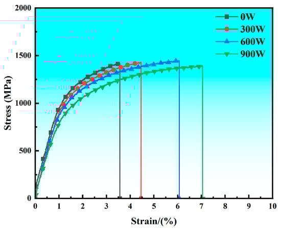
Figure 15.
Stress–strain curves of thermal-field-assisted laser-cladded Stellite 6 coating.
Table 5.
Tensile test results of thermal-field-assisted laser-cladded Stellite 6 coating.
However, at 600 W induction heating power, the sample exhibited the most balanced combination of strength and ductility, with a yield strength of 906 MPa and an ultimate tensile strength of 1440 MPa, only a slight reduction from the initial values (1046 MPa and 1512 MPa, respectively). Importantly, the elongation increased significantly from 4.37% (0 W) to 6.12% (600 W), indicating a substantial improvement in plasticity without a significant loss in strength. For the intended application of a valve sealing-surface hardfacing layer, where crack-free integrity and good wear resistance (with hardness as a practical indicator) are primary requirements and improved ductility is desirable to mitigate brittle failure, the 600 W condition therefore represents the most appropriate processing window in this study. The microstructure is a key factor governing the yield strength. According to the Hall–Petch relationship (Equation (2)), a reduced grain size generally leads to a higher yield strength. In this work, the microstructural coarsening induced by increasing thermal assistance power is evidenced by the increase in the equiaxed grain size DE (Figure 9) and is consistent with the observed decrease in yield strength.
Dislocation density is another major factor affecting the yield strength of materials. The higher the dislocation density, the stronger the interaction between dislocations, the greater the slip resistance, and thus the higher the yield strength [36,37]. The dislocation strengthening equation [38,39] is shown in (3), where α, M, and b are all positive constants. Combined with the EBSD analysis results, the dislocation densities of the 0 W, 300 W, 600 W, and 900 W samples are 7.3 × 10¹⁴/m2, 6.4 × 10¹⁴/m2, 4.4 × 10¹⁴/m2, and 3.9 × 10¹⁴/m2, respectively. Clearly, as the thermal assistance power increases, the dislocation density of the samples gradually decreases, leading to a gradual decrease in the yield strength of the samples.
where σD is the yield strength of the material, α is the strengthening coefficient, M is the Taylor factor, b is the Burgers vector magnitude, τ is the shear modulus, taken as 63 GPa [40], and ρGND is the dislocation density of the sample.
σD = αMbτρGND½
In summary, after applying thermal field assistance, the increased heat accumulation in the sample structure causes grain growth, which in turn affects the reduction in dislocation density, leading to a gradual decrease in the yield strength of the samples and a gradual increase in elongation. The 600 W sample exhibited the optimal comprehensive tensile properties. Compared to the 0 W sample without thermal field assistance, its yield strength decreased by about 12.8%, but its ultimate tensile strength and elongation increased by about 2.0% and 70.3%, respectively. This shows that adjusting the appropriate thermal assistance power can effectively improve the plasticity and toughness of the cobalt-based alloy cladding layer.
Figure 16 shows SEM images of the tensile fracture morphology of the four samples. From Figure 16(a1)–(d1), it can be seen that the macroscopic fracture of the Stellite 6 coating is relatively flat, without significant macroscopic plastic deformation, indicating brittle fracture. Observation under a high-magnification electron microscope is shown in Figure 16(a2)–(d2). Fracture morphology along dendrites can be observed at high magnification, with many tear ridges (white arrows) around the dendrites. Small and shallow dimples (yellow arrows) are distributed inside the dendrites, mainly due to the large amount of FCC-structured γ-Co solid solution in the cladding-layer matrix [41]. Furthermore, many small cleavage facets (green arrows) are present on the fracture surface, and the fracture mechanism is a typical quasi-cleavage fracture.
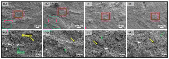
Figure 16.
Fracture surface morphology of thermal-field-assisted laser-cladded Stellite 6 coating after tensile test: (a1,a2) 0 W; (b1,b2) 300 W; (c1,c2) 600 W; (d1,d2) 900 W. The red box in (a1–d1) marks the area shown at higher magnification in the corresponding images (a2–d2).
4. Conclusions
This paper successfully prepared Stellite 6 cobalt-based alloy coatings without macroscopic defects on 17-4PH stainless steel substrates using in situ induction-heating thermal-field-assisted laser cladding technology with different induction heating powers. The macroscopic morphology, microstructure, and mechanical properties were studied, yielding the following main conclusions:
- (1)
- In situ induction-heating thermal field assistance improved coating appearance and effectively suppressed hot cracking. Surface roughness first decreased and then increased with heating power, with the minimum roughness achieved at 600 W (Sa ≈ 16.67 μm).
- (2)
- The coating mainly consisted of γ-Co and carbide phases (M23C6 and M7C3), and ε-Co appeared after thermal assistance. EBSD maps show that ε-Co and carbides preferentially distribute in interdendritic regions.
- (3)
- Increasing heating power promoted microstructural coarsening (increased DE and SDAS), leading to reduced hardness and strength but improved ductility (537.1 → 461.5 HV0.1; 1046 → 849 MPa for yield strength; 1512 → 1423 MPa for UTS; 4.37% → 6.27% elongation). Fracture surfaces indicate a quasi-cleavage-dominated brittle fracture mode.
- (4)
- The 600 W condition delivered the best overall performance, providing the most favorable strength–ductility balance with the lowest roughness.
Author Contributions
Conceptualization, Q.C.; methodology, Y.S.; validation, X.D. and X.Q.; formal analysis, Y.S. and Y.L.; investigation, X.D. and W.R.; resources, Z.Z.; data curation, Y.L.; writing—original draft preparation, Q.C.; writing—review and editing, Y.S. and X.Z.; visualization, X.D.; supervision, W.T. and X.Z.; project administration, X.D. and X.Z. All authors have read and agreed to the published version of the manuscript.
Funding
This research received no external funding.
Institutional Review Board Statement
Not applicable.
Informed Consent Statement
Not applicable.
Data Availability Statement
Data are contained within the article.
Conflicts of Interest
The authors declare no conflicts of interest.
References
- Zhang, Z.W.; Zuo, D.G.; Lai, Y.T. Failure reason for valve stem of 17-4PH stainless steel. Corros. Prot. 2022, 43, 65–68+73. [Google Scholar] [CrossRef]
- Liu, L.; Shao, L.; Sun, Y.R.; Cui, Z.S.; Li, K.W.; Li, W.S. Microstructure and tribological properties of laser gas nitriding layers of 17-4PH stainless steel. Surf. Technol. 2024, 53, 57–63. [Google Scholar] [CrossRef]
- Park, C.K.; Lee, J.H.; Kang, N.H.; Chun, E.J. Correlation between Microstructure and Tribological Properties of Laser Surface Heat-Treated Stellite Coatings. Coatings 2020, 10, 433. [Google Scholar] [CrossRef]
- Zhang, H.B.; Xu, L.; Yu, X.J. Causes and control measures of cracks on Co-based alloy overlay. J. Xihua Univ. (Nat. Sci. Ed.) 2025, 44, 75–86. [Google Scholar]
- Xu, K.; Liu, H.Q.; Xue, X.C.; Zheng, H.L. Cracking reason analysis of balance disk of steam-driven feed-water pump. Hot Work. Technol. 2019, 48, 248–251. [Google Scholar] [CrossRef]
- Tian, H.Y. Analysis of deep hole surfacing technology for sealing surface of valve body in power station. Technol. Innov. Appl. 2013, 99. [Google Scholar] [CrossRef]
- Sefene, E.M. State-of-the-art of selective laser melting process: A comprehensive review. J. Manuf. Syst. 2022, 63, 250–274. [Google Scholar] [CrossRef]
- Qin, C.P.; Zheng, Y.G. Cavitation erosion behavior of a laser clad Co-based alloy on 17-4PH stainless steel. Corros. Sci. Prot. Technol. 2011, 23, 209–213. [Google Scholar]
- Sun, J.Y.; Yan, Y.L.; Li, B.; Shi, Q.J.; Xu, T.S.; Zhang, Q.L.; Yao, J.H. Comparative study on cavitation-resistance and mechanism of stellite-6 coatings prepared with supersonic laser deposition and laser cladding. Chin. J. Lasers 2021, 48, 182–192. [Google Scholar]
- Ren, C. Research on Microstructure and Properties of Stellite6 Coating by Laser Cladding on 17-4PH Stainless Steel. Master’s Thesis, Shanghai Jiao Tong University, Shanghai, China, 2017. [Google Scholar]
- Gao, H.R.; Li, J.K.; Zhang, Z.W.; Zheng, K.Y.; Xiang, H.H.; Wei, Q.S. Research status and prospect of multi-field modulated metal laser additive manufacturing (invited). Chin. J. Lasers 2024, 51, 99–121. [Google Scholar] [CrossRef]
- Chen, X.; Xie, X.; Wu, H.; Ji, X.; Shen, H.; Xue, M.; Wu, H.; Chao, Q.; Fan, G.; Liu, Q. In-situ control of residual stress and its distribution in a titanium alloy additively manufactured by laser powder bed fusion. Mater. Charact. 2023, 201, 112953. [Google Scholar] [CrossRef]
- Baek, G.Y.; Lee, K.Y.; Park, S.H.; Shim, D.S. Effects of substrate preheating during direct energy deposition on microstructure, hardness, tensile strength, and notch toughness. Met. Mater. Int. 2017, 23, 1204–1215. [Google Scholar] [CrossRef]
- Dalaee, M.T.; Gloor, L.; Leinenbach, C.; Wegener, K. Experimental and numerical study of the influence of induction heating process on build rates Induction Heating-assisted laser Direct Metal Deposition (IH-DMD). Surf. Coat. Technol. 2020, 384, 125275. [Google Scholar] [CrossRef]
- Fan, W.; Tan, H.; Zhang, F.Y.; Feng, Z.; Wang, Y.X.; Hu, Y.L.; Lin, X.; Huang, W.D. Effect of synchronous induction heating on residual stress for laser-based directed energy deposition of thin-walled structures. Mater. Today Commun. 2023, 35, 105702. [Google Scholar] [CrossRef]
- GB/T 228.1-2021; Metallic Materials—Tensile Testing—Part 1: Method of Test at Room Temperature. Standards Press of China: Beijing, China, 2021.
- Huang, T.; Shu, L.S.; Chen, X.D.; Lu, J.J. Effect of laser remelting power on microstructure and properties of Ni-based superalloy cladding coating. Trans. Mater. Heat Treat. 2024, 45, 198–206. [Google Scholar] [CrossRef]
- Betteridge, W. The properties of metallic cobalt. Prog. Mater. Sci. 1980, 24, 51–142. [Google Scholar] [CrossRef]
- Thawari, N.; Gullipalli, C.; Katiyar, J.K.; Gupta, T.V.K. Influence of buffer layer on surface and tribomechanical properties of laser cladded Stellite 6. Mater. Sci. Eng. B-Adv. Funct. Solid-State Mater. 2021, 263, 114799. [Google Scholar] [CrossRef]
- Farnia, A.; Ghaini, F.M.; Rao, J.C.; Ocelík, V.; De Hosson, J.T.M. Effect of Ta on the microstructure and hardness of Stellite 6 coating deposited by low power pulse laser treatments. Surf. Coat. Technol. 2012, 213, 278–284. [Google Scholar] [CrossRef]
- Wu, Y.; Liu, Y.; Chen, H.; Chen, Y.; Li, H.Y.; Yi, W. Microstructure evolution and crack propagation feature in thermal fatigue of laser-deposited Stellite 6 coating for brake discs. Surf. Coat. Technol. 2019, 358, 98–107. [Google Scholar] [CrossRef]
- Yang, P.F.; Lu, N.N.; Liang, J.J.; Guo, Y.M.; Zhang, G.R.; Song, X.; Zhou, Y.Z.; Sun, X.F.; Li, J.G. Hot Crack Formation Mechanism and Inhibition of a Novel Cobalt-Based Alloy Coating during Laser Cladding. Materials 2024, 17, 3914. [Google Scholar] [CrossRef]
- Smoqi, Z.; Toddy, J.; Halliday, H.; Shield, J.E.; Rao, P. Process-structure relationship in the directed energy deposition of cobalt-chromium alloy (Stellite 21) coatings. Mater. Des. 2021, 197, 109229. [Google Scholar] [CrossRef]
- Jose, S.A.; Lapierre, Z.; Williams, T.; Hope, C.; Jardin, T.; Rodriguez, R.; Menezes, P.L. Wear- and Corrosion-Resistant Coatings for Extreme Environments: Advances, Challenges, and Future Perspectives. Coatings 2025, 15, 878. [Google Scholar] [CrossRef]
- Yang, Z.Y.; Jian, Y.X.; Chen, Z.H.; Qi, H.J.; Huang, Z.F.; Huang, G.S.; Xing, J.D. Microstructure, hardness and slurry erosion-wear behaviors of high-speed laser cladding Stellite 6 coatings prepared by the inside-beam powder feeding method. J. Mater. Res. Technol.-JMRT 2022, 19, 2596–2610. [Google Scholar] [CrossRef]
- Li, L.; Sun, F.; Zhang, R.C. Effect of solution treatment on the performance of laser cladding of Stellite6 alloy coating. Surf. Technol. 2017, 46, 78–81. [Google Scholar] [CrossRef]
- Cui, C.; Wu, M.P.; He, R.; Gong, Y.L.; Miao, X.J. Understanding Stellite-6 coating prepared by laser cladding: Convection and columnar-to-equiaxed transition. Opt. Laser Technol. 2022, 149. [Google Scholar] [CrossRef]
- Song, B.X.; Yu, T.B.; Jiang, X.Y.; Xi, W.C.; Lin, X.L. Development mechanism and solidification morphology of molten pool generated by laser cladding. Int. J. Therm. Sci. 2021, 159, 106579. [Google Scholar] [CrossRef]
- Zhang, W.G.; Liu, L.; Zhao, X.B.; Huang, T.W.; Yu, Z.H.; Qu, M.; Fu, H.Z. Effect of cooling rates on dendrite spacings of directionally solidified DZ125 alloy under high thermal gradient. Rare Met. 2009, 28, 633–638. [Google Scholar] [CrossRef]
- Calcagnotto, M.; Ponge, D.; Demir, E.; Raabe, D. Orientation gradients and geometrically necessary dislocations in ultrafine grained dual-phase steels studied by 2D and 3D EBSD. Mater. Sci. Eng. A-Struct. Mater. Prop. Microstruct. Process. 2010, 527, 2738–2746. [Google Scholar] [CrossRef]
- Liu, X.; Meng, L.; Zeng, X.Y.; Zhu, B.B.; Wei, K.W.; Cao, J.M.; Hu, Q.W. Studies on high power laser cladding Stellite 6 alloy coatings: Metallurgical quality and mechanical performances. Surf. Coat. Technol. 2024, 481. [Google Scholar] [CrossRef]
- Tian, L.-Y.; Lizárraga, R.; Larsson, H.; Holmström, E.; Vitos, L. A first principles study of the stacking fault energies for fcc Co-based binary alloys. Acta Mater. 2017, 136, 215–223. [Google Scholar] [CrossRef]
- Sun, F.Z.; Cai, K.Q.; Li, X.X.; Pang, M. Research on Laser Cladding Co-Based Alloy on the Surface of Vermicular Graphite Cast Iron. Coatings 2021, 11, 1241. [Google Scholar] [CrossRef]
- Kiehl, M.; Scheid, A.; Graf, K.; Ernst, B.; Tetzlaff, U. Coaxial Laser Cladding of Cobalt-Base Alloy Stellite™ 6 on Grey Cast Iron Analysis of the Microstructural and Mechanical Properties Depending on the Laser Power. J. Mater. Eng. Perform. 2023, 32, 3821–3838. [Google Scholar] [CrossRef]
- Deng, J.Q.; Wang, G.J.; Qi, H.J.; Liu, Y.; Huang, Z.F. Thermal compensation strategy in selective electron beam melting: Tailoring the microstructure and mechanical properties of H13 tool steel. Mater. Des. 2025, 253, 113880. [Google Scholar] [CrossRef]
- Huang, G.; Wei, K.W.; Deng, J.F.; Zeng, X.Y. High power laser powder bed fusion of 18Ni300 maraging steel: Processing optimization, microstructure and mechanical properties. Mater. Sci. Eng. A-Struct. Mater. Prop. Microstruct. Process. 2022, 856, 143983. [Google Scholar] [CrossRef]
- Tekumalla, S.; Seita, M.; Zaefferer, S. Delineating dislocation structures and residual stresses in additively manufactured alloys. Acta Mater. 2024, 262, 119413. [Google Scholar] [CrossRef]
- Qi, H.J.; Huang, Z.F.; Yang, Z.Y.; Deng, J.Q.; Chen, Z.H.; Wang, J.; Jian, Y.X. A novel pathway to realize the columnar-to-equiaxed transition and mechanical anisotropy suppression in SEBM of 316L. J. Mater. Process. Technol. 2026, 347, 119155. [Google Scholar] [CrossRef]
- Huang, G.; Wei, K.W.; Zeng, X.Y. Microstructure and mechanical properties of H13 tool steel fabricated by high power laser powder bed fusion. Mater. Sci. Eng. A-Struct. Mater. Prop. Microstruct. Process. 2022, 858, 144154. [Google Scholar] [CrossRef]
- Yang, D.Z.; Hua, C.; Qu, S.Z.; Xu, J.J.; Chen, J.M.; Yu, C.; Lu, H. Isothermal Transformation of -Co to ε-Co in Stellite 6 Coatings. Metall. Mater. Trans. A-Phys. Metall. Mater. Sci. 2019, 50A, 1153–1161. [Google Scholar] [CrossRef]
- Chang, S.S.; Wu, H.C.; Chen, C. Impact wear resistance of Stellite 6 hardfaced valve seats with laser cladding. Mater. Manuf. Process. 2008, 23, 708–713. [Google Scholar] [CrossRef]


Disclaimer/Publisher’s Note: The statements, opinions and data contained in all publications are solely those of the individual author(s) and contributor(s) and not of MDPI and/or the editor(s). MDPI and/or the editor(s) disclaim responsibility for any injury to people or property resulting from any ideas, methods, instructions or products referred to in the content. |
© 2026 by the authors. Licensee MDPI, Basel, Switzerland. This article is an open access article distributed under the terms and conditions of the Creative Commons Attribution (CC BY) license.