Abstract
Oily wastewater poses severe ecological and health threats, but conventional separation technologies have limitations like low efficiency or high energy consumption. Herein, two superwettable carbon fiber (CF)-based membranes were fabricated for efficient oil–water separation. Using CF (low cost, excellent mechanical stability) as the substrate, Cu-TiO2@CF (superhydrophilic/underwater superoleophobic, renewable) was prepared via a deep ultraviolet (DUV)-assisted sol–gel method, and OTMS/Cu-TiO2@CF (superhydrophobic/superoleophilic) was obtained by modifying Cu-TiO2@CF with octadecyltrimethoxysilane (OTMS) via hydrothermal synthesis. Characterization showed Cu-TiO2 coatings uniformly covered CF, with strong substrate bonding. Both membranes exhibited outstanding performance: Cu-TiO2@CF achieved water fluxes of up to 79,839.6 L·m−2·h−1 and >97.3% separation efficiency for four oil–water mixtures; OTMS/Cu-TiO2@CF had a maximum oil flux of 86,593.4 L·m−2·h−1 and >98.1% efficiency. Cu-TiO2@CF regenerated via 10 min UV irradiation (restoring underwater oil contact angle to 153°), while OTMS/Cu-TiO2@CF achieved recovery through the process of UV irradiation followed by OTMS re-modification. Both membranes maintained stable performance over 100 cycles, demonstrating considerable potential for engineering applications.
1. Introduction
With the deepening of industrialization, a large volume of oily wastewater is generated across industries such as oilfield exploitation, iron and steel smelting, mechanical processing, textile production, pharmaceutical engineering, and food manufacturing [,,,,]. Oil contaminants in this wastewater impede aquatic photosynthesis, leading to the death of aquatic organisms; upon infiltrating soil, they further damage the soil structure, posing severe threats to both the ecological environment and human health [,,]. To address oily wastewater pollution, technologies including gravity sedimentation, centrifugal separation, adsorption, chemical separation, biological treatment, and membrane separation have been applied in oil–water separation [,]. However, these technologies have distinct limitations, such as low efficiency, high costs, and susceptibility to secondary pollution [,,,,]. In contrast, membrane separation technology leverages differences in interfacial interactions between membranes and oil/water (e.g., superwetting properties and pore size sieving effect) to achieve efficient, chemical-free, and low-energy separation through physical interception, demonstrating remarkable advantages [,,]. In particular, superwetting oil–water separation membranes, through the innovative mechanism of “replacing physical sieving with surface wettability”, have overcome the limitations of pore size sieving membranes in terms of applicability to complex systems, antifouling capability, and energy consumption control, thus emerging as the mainstream development direction for oil–water separation membrane materials [,,,]. Among various superwetting oil–water separation membranes [,,,], the “water-permeable and oil-repellent” superhydrophilic/underwater superoleophobic membranes and the “oil-permeable and water-repellent” superhydrophobic/superoleophilic membranes are considered the most promising for engineering applications, owing to their stable performance and excellent oil–water selectivity [].
According to differences in substrate materials, superwetting oil–water separation membranes can be divided into three major categories: polymer-based, metal-based, and inorganic non-metallic-based. Polymer superwetting oil–water separation membranes often use materials such as polyvinylidene fluoride (PVDF), polyacrylonitrile, or polylactic acid as substrates and possess advantages of excellent separation performance and easy processability [,,,,]. However, they usually have poor mechanical properties, and membrane pores are prone to deformation and rupture after repeated use. Metal-based superwetting oil–water separation membranes are mostly prepared using copper meshes, stainless steel meshes, or metal foams as substrates, with the introduction of superwetting coatings or construction of micro–nano-structures, and offer advantages such as low cost, excellent mechanical strength, and ease of mass production [,,,,]. However, the bonding force between the superwetting coating and the metal substrate is weak, leading to frequent peeling of the surface coating and reduced membrane durability. Common substrates for inorganic non-metallic superwetting oil–water separation membranes include ceramics, carbon-based materials, and glass fibers [,,,]. Among these, carbon-based oil–water separation membrane materials (especially carbon fibers, CFs) not only exhibit resistance to acids, alkalis, and organic solvents but also possess better flexibility, tear resistance, and higher impact strength compared to ceramic nanofiber membranes, making them a widely studied material category currently [,]. It should be noted that although CF membranes inherently have hydrophobic and oleophilic properties, their selective permeability/repellency towards oil and water is relatively weak, precluding their direct application in oil–water separation. Therefore, endowing CF membranes with superwetting properties is a prerequisite for their application in oil–water separation. For instance, Sun et al. [] prepared a flexible superhydrophobic/superoleophilic CF membrane via electrospinning and fluorination treatment, achieving an oil flux of 3590 L·m−2·h−1·bar−1 in petroleum ether/water separation. Nevertheless, electrospinning technology suffers from low production efficiency, which cannot meet the requirements of large-scale industrial production []. Modifying the surface of CF membranes directly to impart superwetting properties is expected to reduce raw material costs and significantly improve production efficiency. However, conventional methods such as magnetron sputtering, physical vapor deposition, chemical vapor deposition, and electrochemical deposition struggle to deposit fully coated functional layers on non-planar fibers. Although the low-cost sol–gel method can coat functional layers on non-planar fiber substrates, the conversion of gel coatings to ceramic functional coatings involves substantial volume shrinkage, causing the functional coating to crack and peel off easily []. Fortunately, Chen et al. [,] reported a deep ultraviolet (DUV)-assisted sol–gel method. They confirmed that high-energy photons emitted by DUV lamps can penetrate the gel film, triggering free radical generation reactions and enabling the conversion of gel films to ceramic films under low-temperature conditions. Additionally, this method not only mitigates internal stress induced by severe volume shrinkage during gel conversion but also effectively reduces pore defects inside the coating by facilitating the gradual release of exhaust gases, resulting in high-density ceramic coatings. We speculate that depositing superwetting ceramic coatings on CF substrates using the DUV-assisted sol–gel method may enhance the bonding strength and compactness of the coating, thereby promising excellent durability in oil–water separation applications.
In practical oil–water separation processes, the surface of superwetting membranes is prone to fouling due to the complex composition of oil–water mixtures, which in turn impairs their wettability []. In recent years, titanium dioxide (TiO2) has been widely utilized in organic pollutant degradation, wastewater treatment, and oil–water mixture recovery, thanks to its non-toxicity, high catalytic activity, low cost, and excellent hydrophilicity. This provides a feasible strategy for the regeneration of superwetting membranes [,,]. Based on the above premise, a renewable water-permeable membrane material (Cu-TiO2@CF) with outstanding photocatalytic degradation performance was fabricated via a deep ultraviolet (DUV) irradiation-assisted sol–gel method. Subsequently, octadecyltrimethoxysilane (OTMS) was used as a modifier to regulate the wettability of Cu-TiO2@CF through hydrothermal synthesis, resulting in the formation of a superhydrophobic/superoleophilic oil-permeable membrane material (OTMS/Cu-TiO2@CF). Satisfactorily, both membrane materials exhibited excellent oil–water separation performance and durability.
2. Materials and Methods
2.1. Materials
CF materials were purchased from Jiangsu Hengshen Co., Ltd. (Zhenjiang, China). The carbon content of the CF materials is more than 99%, with a density of 0.13 g/cm3, a tensile strength of 0.14 MPa, and a compressive stress of 10 MPa under 10% compression. Gasoline (Gas) was obtained from China Petroleum & Chemical Corporation (Sinopec) (Beijing, China). Other reagents, including nitric acid (HNO3), copper nitrate (Cu (NO3)2·5H2O), tetrabutyl titanate, octadecyltrimethoxysilane (OTMS), cyclohexane (CyH), chlorobenzene (CB), petroleum ether (PE), and absolute ethanol, were sourced from Sinopharm Chemical Reagent Co., Ltd. (Shanghai, China). All experimental reagents were of analytical grade and required no further treatment.
2.2. Pretreatment of CF Raw Materials
First, CFs were placed in a Na2CO3 solution with a mass fraction of 1%. After ultrasonic soaking for 1 h, the fibers were rinsed with deionized water to remove surface dust. Subsequently, the CFs were fully immersed in dilute HNO3 with a mass fraction of 15%. After continuous immersion for 2 h, the CFs were taken out and rinsed repeatedly with deionized water. This rinsing process was continued until the pH value of the rinsing solution reached 7 through detection. Afterwards, excess water on the surface of the CFs was spun off, followed by drying.
2.3. Preparation of Cu-TiO2@CF Membranes
Given that Cu-doped TiO2 exhibits superior photocatalytic performance [], a Cu-TiO2 sol with a Cu ion doping concentration of 5w% was prepared in this study. The specific preparation process is as follows: First, 3.24 g of tetrabutyl titanate was weighed and dissolved in 39.30 g of ethanol, 4.05 g of benzoylacetone was added, and the mixture was stirred for 2 h. Separately, 0.1638 g of Cu (NO3)2·5H2O was weighed and dissolved in 39.30 g of absolute ethanol, followed by stirring for 2 h. Finally, the two solutions were mixed and continuously stirred for 8 h to obtain a stable dark-green Cu-TiO2 sol. Two methods were employed to prepare Cu-TiO2@CF membranes in this study: (1) The hydrothermal method: The pretreated CFs were placed in a high-pressure autoclave, and the Cu-TiO2 sol prepared above was poured in until the CFs were completely submerged. After sealing the autoclave, it was placed in an oven at 120 °C for reaction for 2 h. Upon completion of the reaction, it was naturally cooled, and the CFs were taken out and rinsed with deionized water to remove residual sol on the surface. (2) The sol–gel method combined with DUV-assisted rapid heat treatment technology: The pretreated CFs were immersed in the Cu-TiO2 precursor sol. After 5 min, they were taken out and spun dry, then placed in an oven at 80 °C for drying for 2 h. Subsequently, the sample was irradiated with DUV at 120 °C for 2 h and then placed in a heating furnace at 400 °C for heat treatment for 2 h.
For the Cu-TiO2@CF material prepared via Method 1, its Cu-TiO2 coating exhibits poor compactness and weak bonding strength with the CF matrix, accompanied by severe pulverization. These drawbacks render the material unable to meet the basic requirements for oil–water separation applications. In contrast, the Cu-TiO2@CF membranes fabricated by Method 2 feature a densely coated Cu-TiO2 layer on the surface of the CFs. After repeated rubbing tests, no coating detachment or powdering was observed, indicating significantly superior interfacial bonding performance and structural stability. In conclusion, Method 2 represents the optimal technical route for preparing Cu-TiO2@CF materials.
2.4. Preparation of OTMS/Cu-TiO2@CF Membranes
First, 6.25 mL of OTMS was added into 100 mL of Cu-TiO2 sol, followed by magnetic stirring for 2 h to prepare the OTMS-Cu-TiO2 hydrothermal reaction solution. The Cu-TiO2@CF was placed in a reaction kettle, and the prepared hydrothermal reaction solution was slowly poured in until the Cu-TiO2@CFs were completely submerged. After sealing the reaction kettle, it was placed in an oven at 120 °C for 4 h of heat preservation. Once the reaction kettle had cooled to room temperature along with the furnace, the sample was taken out, rinsed with alcohol three times, and then placed in an oven at 80 °C for drying for 12 h, thus obtaining the target OTMS/Cu-TiO2@CF. A schematic diagram of the preparation process is shown in Figure 1.

Figure 1.
Preparation process diagram of Cu-TiO2@CF and OTMS/Cu-TiO2@CF membranes.
2.5. Material Characterization
X-ray diffraction (XRD, model Shimadzu 7000S, Kyoto, Japan) was used to characterize the crystal structure and phase composition of the pristine CFs and Cu-TiO2 coatings. The X-ray source was Cu Kα radiation (λ = 0.15406 nm), with a test angular range of 5–80° (2θ) and a scanning rate of 10°·min−1. Scanning electron microscopy (SEM, model JSM-7000F, manufactured by JOEL, Tokyo, Japan) was utilized to observe the surface microstructure of the samples. Concurrently, the accompanying energy-dispersive X-ray spectroscopy (EDS) function was employed to determine the element types, relative contents, and distribution patterns in specific regions of the material surface. X-ray photoelectron spectroscopy (XPS, model K-alpha, manufactured by Thermo Fisher Scientific, Waltham, MA, USA) was applied to analyze the surface chemical composition, elemental existence forms, and valence state information of the two membranes: Cu-TiO2@CF and OTMS/Cu-TiO2@CF. The binding energy values were calibrated with reference to the C 1s peak of contaminant carbon at 284.8 eV. An ultraviolet–visible (UV–vis) spectrophotometer (model U-3900H, Hitachi, Tokyo, Japan) was used to measure the UV–vis absorption spectra of Cu-TiO2@CF coatings within the wavelength range of 200–600 nm, thereby analyzing their light absorption properties. An optical surface contact angle (CA) measuring instrument (model JC2000A, manufactured by Dongguan Shengding Precision Instrument Co., Ltd., Dongguan, China) was employed to determine the static CAs of different liquids on the membrane surface, evaluating their surface wettability. For the measurement of water/oil CAs in air, it is sufficient to directly drop deionized CB/water droplets onto the sample surface. However, for the measurement of underwater oil CAs, the sample must first be placed in a beaker filled with water, and then CB droplets are dropped onto the sample surface using a syringe. To facilitate the observation of experimental phenomena, water was stained with methyl blue, and CB was stained with Nile red.
2.6. Performance Testing
2.6.1. Adsorption Performance Testing
In order to characterize the adsorption performance of the materials, the absorption capacity is used to evaluate the material’s absorption ability, while the retention rate is employed to assess its long-term retention capacity for the absorbed liquids. Cu-TiO2@CF and OTMS/Cu-TiO2@CF membranes were firstly immersed in water or oils, respectively. After the samples achieved saturated liquid absorption for 5 min, they were taken out and weighed. Subsequently, the samples were hung in the air and allowed to stand for 5 min until no liquid droplets fell from their surfaces, after which they were weighed again. The absorption capacity and liquid retention rate of the samples were calculated using Equation (1) and Equation (2), respectively [].
where λ is the absorption capacity (g/g), m0 is the mass of the sample, and m is the mass of the sample after saturated liquid absorption, respectively (g).
where γ is the liquid retention rate (%), and w is the mass of the sample after it has fully absorbed the liquid and been hung to stand in a suspended state for 5 min (g).
2.6.2. Wear Resistance Testing
During the actual oil–water separation process, oil–water separation membranes inevitably suffer from surface friction and mechanical wear. This causes damage to the functional coating on the membrane surface, which in turn leads to a decrease in oil–water separation performance, and in severe cases, even a complete loss of performance. In this study, the wear resistance of two samples, Cu-TiO2@CF and OTMS/Cu-TiO2@CF, was tested to verify the bonding strength of the functional coating on the CF surface and predict its durability in oil–water separation operations. In the wear resistance test, the sample was placed on 2000-mesh sandpaper, and an 80 g weight was applied to its surface. The sample was then driven to move 20 cm at a speed of 2 cm/s. Subsequently, the water/oil CA of the samples in the air or underwater was monitored.
2.6.3. Oil–Water Separation Performance
In this study, a bidirectional oil–water separation device, as illustrated in Figure 2, was designed. The device consists of a T-shaped three-way pipe with an inner diameter of 40 mm and a support frame. A flange interface was installed at the lower branch pipe of the three-way pipe, where the Cu-TiO2@CF water-filtering membrane and OTMS/Cu-TiO2@CF oil-filtering membrane—both with a diameter of 40 mm—were fixed separately. For the oil phase, CyH, CB, PE, and Gas were used. Oil–water mixtures were prepared by mixing oil and water at a volume ratio of 1:1, thus simulating four distinct oil–water mixed systems. The volumes of oil and water collected at both ends of the device were recorded separately. Subsequently, the corresponding separation flux and separation efficiency were calculated using Equation (3) and Equation (4), respectively [,].
where σ represents the separation flux (L·m−2·h−1), V is the volume of liquid actually separated (L), t is the permeation separation time (h), and A represents the effective permeation area (m2).
where θ denotes the separation efficiency (%), with Ve standing for the volume of liquid collected after the completion of separation (L) and Vf representing the volume of the initial liquid before separation (L).
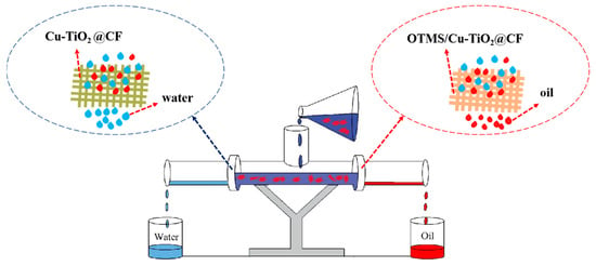
Figure 2.
Schematic diagram of the bidirectional oil–water separation device.
2.7. Restoration of Oil–Water Separation Membranes
After a continuous oil–water separation operation for a certain period of time, the Cu-TiO2@CF water-filtering membrane and OTMS/Cu-TiO2@CF oil-filtering membrane installed at the flange were removed. They were then cleaned with ethanol and n-hexane, respectively, followed by drying. The Cu-TiO2@CF water-filtering membrane could be regenerated directly by irradiating it with a 350 W xenon lamp (Shenzhen Bohan Technology Co., Ltd., Shenzhen, China) for 10 min. For the OTMS-Cu-TiO2 oil-filtering membrane, it was first irradiated with a xenon lamp for 30 min and then re-immersed into the OTMS-Cu-TiO2 hydrothermal reaction solution for reaction, after which its oil-filtering function was restored.
3. Results and Discussion
3.1. Phase Structure Analysis of Cu-TiO2 Coatings
Due to the small thickness of the Cu-TiO2 coating on the surface of the Cu-TiO2@CF sample, it is difficult to obtain strong signals in XRD tests, making this sample unsuitable for characterizing the phase structure of the Cu-TiO2 coating. To verify the phase composition of the Cu-TiO2 coating prepared by the sol–gel method combined with DUV-assisted rapid heat treatment in this study, a Cu-TiO2/Si reference sample was fabricated by depositing a Cu-TiO2 coating on a silicon (Si) substrate under exactly the same experimental conditions as those used for preparing Cu-TiO2@CF. The XRD characterization results of this reference sample are presented in Figure 3. It should be noted that the CF substrate itself has an amorphous structure and thus exhibits no obvious diffraction peaks. In contrast, distinct diffraction peaks are observed in the XRD pattern of the Cu-TiO2/Si reference sample at 2θ values of 25.8°, 37.8°, 48.0°, 53.9°, 55.0°, 62.1°, and 70.3°. These diffraction peaks correspond to the (101), (004), (200), (105), (211), (213), and (220) crystal planes of anatase TiO2, respectively []. This result indicates that the Cu-TiO2 coating prepared on the CF surface by the sol–gel method combined with DUV-assisted rapid heat treatment has a typical anatase crystal structure, and the Cu-doping does not alter the original crystal structure of TiO2.
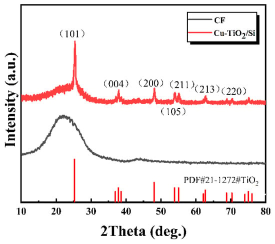
Figure 3.
XRD patterns of CF and Cu-TiO2 coating.
3.2. Analysis of Material Surface Morphology
Figure 4a shows the SEM image of a single CF, revealing a diameter of ~10.5 μm and a micron-scale grooved rough surface structure. SEM images of Cu-TiO2@CF (Figure 4b,c) reveal that the original grooved structure is fully covered by a Cu-TiO2 coating. The coating is crack- and void-free, exhibiting a uniform granular morphology with particle sizes concentrated at 100–300 nm. EDS analysis (Figure 4d–f) confirms the uniform distribution of Ti, O, and Cu across the surface, verifying the uniform and dense coverage of CFs by the Cu-TiO2 coating. For OTMS/Cu-TiO2@CF (Figure 4g), the surface is generally flat and smooth with slight undulations, and no cracks or voids are observed. High-magnification imaging (Figure 4h) shows that the granular structure in the coating is significantly refined to tens of nanometers, much smaller than that of Cu-TiO2@CF. EDS results (Figure 4i–l) demonstrate uniform distribution of Ti, Cu, O, and Si; the presence and uniform distribution of Si (attributed to OTMS) further confirm the compactness and uniformity of the OTMS/Cu-TiO2 composite coating.
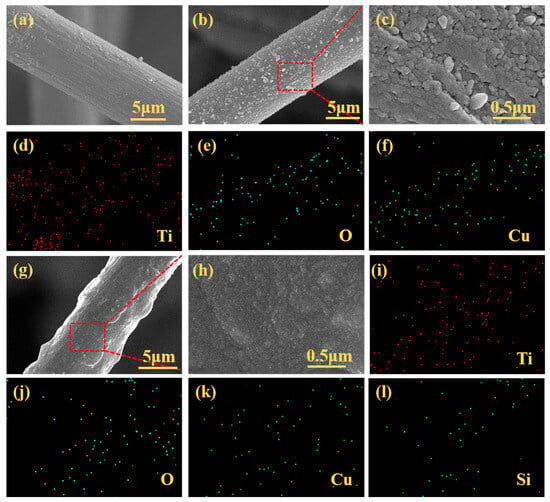
Figure 4.
SEM and EDS images: (a) CF substrate (SEM); (b,c) Cu-TiO2@CF (SEM, magnified SEM); (d–f) Cu-TiO2@CF (EDS); (g,h) OTMS/Cu-TiO2@CF (SEM, magnified SEM); (i–l) OTMS/Cu-TiO2@CF (EDS).
3.3. XPS Analysis
The full-scan XPS spectrum of Cu-TiO2@CF (Figure 5a) shows only characteristic peaks for C, O, Ti, and Cu with no impurity signals, confirming high sample purity and absence of external contamination during preparation. High-resolution scans (Figure 5b–e) reveal the following: C 1s (Figure 5b) deconvolutes into peaks at 284.8 eV (C-C/C=C), 286.2 eV (C-O), and 288.1 eV (C=O) [], attributed to the CF substrate, residual organics, and Cu-TiO2 precursor residues; O 1s (Figure 5c) exhibits peaks at 530.1 eV (lattice Oα in TiO2), 532.2 eV (chemisorbed Oβ), and 535.5 eV (adsorbed water/hydroxyls Oγ), consistent with typical TiO2 oxygen species []; Ti 2p (Figure 5d) shows a doublet at 458.7 eV (Ti 2p3/2) and 464.8 eV (Ti 2p1/2), matching standard anatase TiO2 [,] and confirming Ti exists as TiO2; and Cu 2p (Figure 5e) displays a doublet at 934.2 eV (Cu 2p3/2) and 954.0 eV (Cu 2p1/2) with satellite peaks 9.4 eV and 8.7 eV higher—fingerprints of Cu2+ from d-orbital shake-up transitions [], verifying Cu is doped as Cu2+. These results confirm successful Cu-TiO2 coating on CF with Cu2+ doped into the TiO2 lattice and no impurity phases. For OTMS/Cu-TiO2@CF (Figure 5f), the full-scan spectrum retains C, O, Ti, and Cu peaks but adds a Si peak and shows enhanced C intensity, indicating successful grafting of OTMS molecules onto Cu-TiO2 via Si-O covalent bonds between OTMS alkyl chains and surface hydroxyls, introducing Si and increasing surface C content.
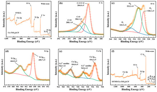
Figure 5.
(a) XPS wide-scan spectrum of Cu-TiO2@CF; high-resolution XPS spectra of (b) C 1s, (c) O 1s, (d) Ti 2p, and (e) Cu 2p for Cu-TiO2@CF; (f) XPS wide-scan spectrum of OTMS/Cu-TiO2@CF.
3.4. Wettability Characterization and Mechanism Analysis
The core function of an oil–water separation membrane is “selective permeation of one phase while retention of the other”, with wettability as the key indicator governing this process []. Herein, deionized water (aqueous phase) and CB (oil phase) were used to characterize the wettability of pristine CF membrane, Cu-TiO2@CF, and OTMS/Cu-TiO2@CF, alongside discussions of their wetting mechanisms. In air, pristine CF membrane slowly spread and absorbed CB droplets (oil CA = 0°, superoleophilic) but had a water CA of only 114° (far below the 150° superhydrophobic threshold), precluding direct use for oil–water separation. Cu-TiO2@CF instantaneously spread and absorbed water droplets (water CA = 0°, superhydrophilic, Figure 6a) []; its wetting mechanism can be explained by the Wenzel model (Figure 7a) [,]: high-electronegativity Ti4+ in Cu-TiO2 enables strong interactions with water (chemical basis for hydrophilicity), while CF’s micron-scale pores and Cu-TiO2’s nano-scale roughness form a micro–nano composite surface that enhances hydrophilicity via capillary action. Underwater, CB formed smooth spheres on Cu-TiO2@CF with an underwater oil CA of 155° (Figure 6b,c), confirming underwater superoleophobicity (CA > 150°); this follows the Cassie–Baxter model (Figure 7b) [], where the hydrophilic surface traps water in rough structure cavities to form a stable “water film”, which acts as a “second region” to suspend oil droplets at the “solid skeleton–retained water” interface. In contrast, OTMS/Cu-TiO2@CF showed opposite wettability: in air, it quickly absorbed CB (oil CA = 0°, superoleophilic; Figure 6d). This is because OTMS modification covers the sample surface with long-chain alkyl groups, significantly reducing the surface energy and achieving a high degree of matching with the surface energy of the low-surface-energy oil phase. Meanwhile, the micro–nano rough structure enhances the oleophilic effect through the “structural amplification effect” of the Wenzel model, ultimately realizing superoleophilicity []. In contrast, water droplets contacting the surface of OTMS/Cu-TiO2@CF in air form a spherical shape (Figure 6e) with a measured water CA of 156° (Figure 6f), confirming superhydrophobicity. This behavior follows the Cassie–Baxter model [,]: the material’s rough structure constructs a “low-surface-energy solid–air” heterogeneous surface, where high roughness elevates the proportion of the “air region”; the resulting “air cushion” suspends water droplets, ultimately yielding superhydrophobicity.
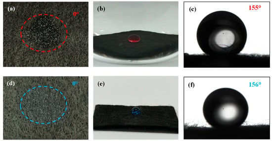
Figure 6.
(a) Wettability of Cu-TiO2@CF towards water in air; (b) wettability of Cu-TiO2@CF towards CB underwater, along with (c) the corresponding CA image; (d) wettability of OTMS/Cu-TiO2@CF towards CB in air; (e) wettability of OTMS/Cu-TiO2@CF towards water in air, along with (f) the corresponding CA image.
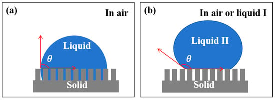
Figure 7.
Classic wetting models: (a) Wenzel Model, (b) Cassie–Baxter model.
3.5. Adsorption Performance
The adsorption capacities of the pristine CF membrane for CB and water were first tested. The results showed that due to the superoleophilic property of CFs, the adsorption capacity of the membrane for CB could reach 4.9 g/g, while its adsorption capacity for water was only 0.012 g/g. The reason for this difference is that the surface atoms of the pristine CF membrane are mainly bonded by non-polar carbon–carbon bonds, and coupled with its inherent porous structure, these two factors together endow it with strong hydrophobicity. As illustrated in Figure 8a, the adsorption capacities of the Cu-TiO2@CF sample for H2O, NaCl aqueous solution, HCl aqueous solution, and NaOH aqueous solution were 8.5, 7.8, 5.9, and 7.2 g/g, respectively. The results demonstrate that Cu-TiO2@CF exhibits good adsorption performance toward both water and electrolyte solutions, a phenomenon that can be attributed to the sample’s low density, outstanding superhydrophilicity, and three-dimensional porous structure [,]. Compared with pure water, the adsorption capacities of the sample for electrolyte solutions are all reduced, with the specific reasons as follows []: in NaCl solution, the ionized Na+ and Cl− disrupt the hydrogen bond network structure of water molecules; in HCl solution, the ionized Cl− also damages the hydrogen bond network of water molecules, and the H+ further undergoes a protonation reaction with the active hydroxyl groups on the Cu-TiO2 surface, thereby altering the surface properties of the material; in NaOH solution, Na+ breaks the hydrogen bond network of water molecules, while OH− reacts with or adsorbs onto the active metal ions on the Cu-TiO2 surface, leading to the destruction of the material’s surface charge structure. Furthermore, the aforementioned ionic effects also result in differences in the liquid retention rates of Cu-TiO2@CF for different solutions. The liquid retention rates for H2O, NaCl aqueous solution, HCl aqueous solution, and NaOH aqueous solution were 90.7%, 89.6%, 87.7%, and 88.4%, respectively, and the order of liquid retention rates is completely consistent with that of adsorption capacities. The oil adsorption performance of the OTMS/Cu-TiO2@CF sample for different oil products is presented in Figure 8b. Its adsorption capacities for CyH, CB, PE, and Gas were 6.2, 6.7, 5.5, and 5.7 g/g, respectively. The relatively high oil adsorption capacity of this sample mainly stems from its low density, excellent superhydrophobicity, and three-dimensional porous structure. The order of oil adsorption capacities is consistent with that of the oil densities, and CB with the highest density exhibits the maximum oil adsorption capacity. In terms of oil retention performance, the oil retention rates of OTMS/Cu-TiO2@CF for CyH, CB, PE, and Gas were 89.1%, 89.7%, 89.7%, and 87.5%, respectively. Undoubtedly, the high oil retention rate benefits from the material’s three-dimensional porous structure and the strong interaction between the low-surface-energy coating and oil molecules []. There are certain differences in the oil retention rates among different oil solvents. On one hand, this is due to the varying molecular polarities of different oils, which lead to differences in the interaction strength between the oils and the surface of the OTMS/Cu-TiO2@CF coating; on the other hand, the viscosities of different oils are different, and the differences in their flow rates also have an impact on the oil retention rate.
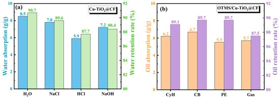
Figure 8.
Adsorption capacity and retention rate of (a) Cu-TiO2@CF and (b) OTMS/Cu-TiO2@CF.
3.6. Mechanical Wear Resistance
Two types of samples, Cu-TiO2@CF and OTMS/Cu-TiO2@CF, were subjected to 20 consecutive mechanical abrasion tests. As shown in Figure 9a, the underwater oil CA of Cu-TiO2@CF exhibits a gradual decreasing trend with increasing abrasion cycles: after 20 abrasion cycles, although its underwater oil CA decreases from the initial 155° to 150°, it still maintains the underwater superoleophobic property. Similarly, the water CA of OTMS/Cu-TiO2@CF also decreases with increasing abrasion cycles. After 20 abrasion cycles, the water CA decreases from 156° before abrasion to 151° but still retains the superhydrophobic performance. These results indicate that both Cu-TiO2@CF and OTMS/Cu-TiO2@CF possess remarkable mechanical wear resistance, implying a strong bonding force between their surface functional coatings and CF substrates.
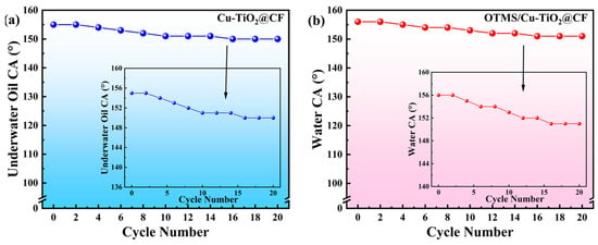
Figure 9.
Variation in CA of samples with mechanical abrasion cycles: (a) Cu-TiO2@CF and (b) OTMS/Cu-TiO2@CF.
To enhance the bonding effect between the coating and the substrate, this study performed cleaning treatment and nitric acid etching pretreatment on CF before functional coating deposition—on one hand removing impurities from the CF surface, and on the other hand increasing its surface roughness through etching, thereby expanding the contact area between the functional coating and CF. After completing the Cu-TiO2 gel coating on the pretreated CF, instead of adopting the one-step “direct heat treatment” process in the traditional sol–gel method, this study innovatively employed a two-step process of “DUV degradation followed by heat treatment” to realize the conversion of Cu-TiO2 gel to Cu-TiO2 ceramic. It should be noted that gel is essentially an organic–inorganic hybrid material, where organic components typically account for more than 50% of the total mass. If the traditional process of direct high-temperature heat treatment is applied to the gel, the organic components will undergo rapid thermal decomposition, accompanied by severe volume shrinkage and pore formation, which not only leads to a significant decrease in coating density but may even cause coating pulverization. In the DUV irradiation process adopted in this study, high-energy photons can penetrate into the Cu-TiO2 gel layer and gradually break the chemical bonds of organic components in the gel; with the participation of oxygen, these organic components are further oxidized into small molecules such as CO2 and H2O, which then escape from the system. This treatment method can not only alleviate the internal stress caused by severe volume shrinkage during the gel conversion process but also effectively reduce the formation of pore defects inside the coating through the gradual release of exhaust gases such as CO2 and H2O, laying a foundation for obtaining high-density Cu-TiO2 ceramic coatings.
3.7. Oil–Water Separation Performance
This study investigated the separation performance of oil–water separation membrane materials for four oil–water mixtures, namely H2O-CyH, H2O-CB, H2O-PE, and H2O-Gas. As shown in Figure 10, after pouring the H2O-CyH mixture into the bidirectional oil–water separation device, driven by gravity, the aqueous phase and CyH oil phase could flow out rapidly from the Cu-TiO2@CF water-filtering membrane end and the OTMS/Cu-TiO2@CF oil-filtering membrane end, respectively, with the entire separation process completed in only a few seconds.
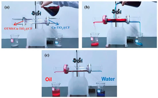
Figure 10.
Pictures of the oil–water separation process: (a) before separation, (b) during separation, and (c) after separation.
Taking 24 h as a continuous separation cycle, the average separation fluxes of the Cu-TiO2@CF water-filtering membrane for the aqueous phase and the OTMS/Cu-TiO2@CF oil-filtering membrane for the oil phase were calculated, respectively, by measuring the volumes of the separated oil and aqueous phases and combining with Equation (3). As can be seen from Figure 11a, after 1 h of separation operation, the separation fluxes of the Cu-TiO2@CF water-filtering membrane for the aqueous phase in the above four oil–water mixtures were 42,088.7, 62,718.6, 79,839.6, and 68,406.7 L·m−2·h−1, respectively. These water flux values are significantly higher than those of the CuCo2O4-coated stainless steel mesh (CuCo2O4-SSM) reported by Zhang et al. [] (Table 1), the ε-polylysine-modified polyvinylidene fluoride membrane anchored via proanthocyanidins (PVDF-PC-εPL) reported by Liu et al. [], and the polyaniline-modified ceramic membrane reported by Salhi et al. []; they are comparable to that of the copper mesh wrapped with CuC2O4 nanosheets reported by He et al. []. Such superior water filtration performance is closely associated with the unique three-dimensional porous structure and outstanding superhydrophilic property of the Cu-TiO2@CF membrane. It should be noted that for the Cu-TiO2@CF water-filtering membrane, the separation efficiency varies slightly across different oil–water mixture systems, all remaining above 97.3%, while the separation flux differs significantly. The notable differences in water flux can be attributed to the combined effect of two factors: the inherent property differences of the oil–water mixtures and the dynamic interactions at the membrane–liquid interface, both of which influence the water mass transfer efficiency. The core separation mechanism of the superhydrophilic water-filtering membrane is “water preferentially wets and permeates through the membrane pores, while oil is retained to form a barrier layer” []. However, the physical properties of the oil phase, such as viscosity, density, and surface tension, directly alter the resistance during the water permeation process; secondly, the different dispersion states of the oil–water mixtures lead to variations in oil droplet size, which in turn affects the “effective filtration area” of the water-filtering membrane; in addition, the polarity differences of different oil molecules change the interaction strength between the oil molecules and the superhydrophilic membrane surface, resulting in different “adsorption–desorption” equilibrium rates of the oil phase on the membrane surface, which further affects the water flux. After 24 h of continuous separation, the separation fluxes of the Cu-TiO2@CF water-filtering membrane for the aqueous phase in the four mixtures decreased to 41,965.5, 62,309.6, 79,177.9, and 68,081.8 L·m−2·h−1, respectively, with flux decay rates of only 0.3%, 0.6%, 0.8%, and 0.5%, respectively. Meanwhile, the separation efficiency of the water-filtering membrane for the aqueous phase in the four mixtures was calculated by combining with Equation (4), and it was found that all separation efficiencies were above 97.0%. The above results indicate that the Cu-TiO2@CF water-filtering membrane, relying on its unique three-dimensional porous structure, excellent superhydrophilic property, and good stability, exhibits high separation flux, high separation efficiency, and outstanding performance stability.
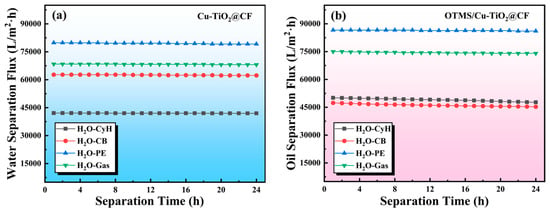
Figure 11.
(a) Separation flux of Cu-TiO2@CF water-filtering membrane for water and (b) separation flux of OTMS/Cu-TiO2@CF oil-filtering membrane for oils.

Table 1.
Comparison of water fluxes of several reported water-filtering membranes.
The variation in separation flux of the OTMS/Cu-TiO2@CF oil-filtering membrane for the oil phase in different oil–water mixtures with time is presented in Figure 11b. After 1 h of separation operation, the separation fluxes of this membrane for CyH, CB, PE, and Gas were 50,109.1, 47,375.9, 86,593.4, and 75,032.5 L·m−2·h−1, respectively, with all separation efficiencies reaching over 98.1%. These oil flux values are several times higher than those of the polylactic acid membrane reported by Zhang et al. [] (Table 2), the electrospun carbon fiber (CF/Ni/F) membrane reported by Sun et al. [], the polyphenylene-sulfide-modified glass fiber cloth (PPS@MGFC) reported by Qi et al. [], the sodium-methyl-silicate-modified cotton cloth (SMS-O-CF) reported by Wang et al. [], and the carbon nanofiber membrane (CFMHF) reported by Sun et al. [], demonstrating superior oil–water separation performance. The differences in the oil–water separation performance must also be attributed to the inherent variations in the oil phase, such as viscosity, density, polarity, and dispersibility. Among these systems, the oil-filtering membrane exhibited the highest separation flux for PE, and this phenomenon is directly associated with the lowest viscosity of PE. In accordance with the principles of fluid mass transfer, a lower viscosity of the oil phase results in less flow resistance when the oil passes through the membrane pores, leading to a higher permeation rate and consequently a significantly higher separation flux []. After 24 h of continuous oil–water separation testing, no obvious decrease was observed in the separation flux of the membrane for each oil phase. This indicates that the OTMS/Cu-TiO2@CF oil-filtering membrane also possesses good performance stability.

Table 2.
Comparison of oil fluxes of several reported oil-filtering membranes.
3.8. Regeneration Performance
After 20 cycles of use, the underwater oil CA of the Cu-TiO2@CF water-filtering membrane decreased slightly from 155° to 154° (Figure 12a), further confirming its remarkable performance stability during oil–water separation. However, when the cycling was extended to 30 times, the underwater oil CA dropped sharply to 146°, indicating the loss of underwater superoleophobicity. This is because although the surface of the superhydrophilic water-filtering membrane preferentially interacts with water, the oil phase can still adsorb onto the membrane surface and pore walls through van der Waals forces and polar interactions, resulting in reduced surface polarity and surface energy of the membrane, weakened hydrophobicity, and enhanced oleophilicity. Subsequently, the used water-filtering membrane was cleaned with ethanol, dried, and then irradiated with xenon lamp UV light for 10 min. Its underwater oil CA recovered to 153°, and the separation flux for the aqueous phase in the H2O-CyH mixture remained at 42,027.6 L·m−2·h−1. This demonstrates that UV irradiation can regenerate the superwetting properties and oil–water separation function of the Cu-TiO2@CF water-filtering membrane. The mechanism is as follows: The Cu-TiO2 coating, as an excellent photocatalytic material with a band gap of 3.31 eV, can strongly absorb ultraviolet light below 370 nm (Figure 12b). Upon excitation by UV light, electrons in the valence band jump to the conduction band, forming electron–hole pairs. The holes oxidize adsorbed water/hydroxyl groups to generate ·OH, while the electrons reduce O2 to produce ·O2− and other reactive free radicals. These highly oxidizing free radicals can gradually oxidize and decompose oil molecules adsorbed on the membrane surface into CO2 and H2O, restoring the membrane surface to a clean state []. The underwater oil CA of the Cu-TiO2@CF water-filtering membrane decreases slowly with increasing cycles and regeneration times. After 110 repeated uses, the underwater oil CA of the regenerated water-filtering membrane can only recover to 149°, losing its underwater superoleophobicity. This is because the water-filtering membrane must withstand mechanical forces such as gravity, operating pressure, and water flow scouring in practical applications, and long-term operation leads to gradual damage to the surface coating, making infinite regeneration cycles impossible. Nevertheless, its ability to undergo over 100 regeneration cycles fully demonstrates its exceptional stability and engineering application prospects.
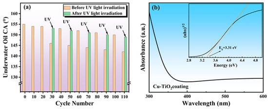
Figure 12.
(a) Effects of cycling times and UV irradiation on underwater oil CA of Cu-TiO2@CF; (b) UV–vis absorption spectrum of Cu-TiO2 coating (the inset is its Tauc plot).
The OTMS/Cu-TiO2@CF oil-filtering membrane exhibits superior cycling performance: after 60 cycles of oil–water separation experiments, its water CA decreased from the initial 156° to 149°. The decline in hydrophobicity may be attributed to membrane fouling and the destruction of OTMS-modified functional groups. Recent studies have demonstrated that C4–C6 fluorosilanes or perfluoropolyether (PFPE) derivatives possess lower surface energy, better thermal stability, chemical stability, and wear resistance compared to OTMS [], while reducing environmental concerns associated with long-chain polyfluoroalkyl substances. In future research, modifying Cu-TiO2@CF with PFPE derivatives is expected to achieve enhanced sustainability. Additionally, the OTMS/Cu-TiO2@CF oil-filtering membrane with degraded performance can also be regenerated. After 30 min of ultraviolet irradiation and subsequent re-modification with OTMS via a hydrothermal reaction, its water CA can recover to over 155°. Even after 100 cycles, the water CA remains at 152°. Recently, some superhydrophobic/superoleophilic oil–water separation materials, such as graphene-modified luffa sponges [] and cotton textiles modified with ZnO sol and 3-mercaptopropyltrimethoxysilane [], have been reported to exhibit a cycling performance of approximately 10 cycles. However, they are unable to restore their superwettability and oil–water separation functionality through regeneration. Thus, the OTMS/Cu-TiO2@CF oil-filtering membrane prepared in this study demonstrates attractive regenerative cycling performance.
4. Conclusions
Two high-performance CF-based oil–water separation membranes (Cu-TiO2@CF and OTMS/Cu-TiO2@CF) with tailored superwettability were successfully developed. The DUV-assisted sol–gel method ensured uniform, dense Cu-TiO2 coatings on CF, enhancing mechanical stability; both membranes retained superwettability after 20 wear cycles. Cu-TiO2@CF (superhydrophilic/underwater superoleophobic) and OTMS/Cu-TiO2@CF (superhydrophobic/superoleophilic) achieved high separation fluxes (up to 79,839.6 and 86,593.4 L·m−2·h−1, respectively) and >97.3% efficiency for H2O-CyH, H2O-CB, H2O-PE, and H2O-Gas mixtures, with minimal flux decay (<1%) after 24 h continuous separation. Notably, the Cu-TiO2 coating’s photocatalytic property enabled membrane regeneration: Cu-TiO2@CF can be recovered via 10 min UV irradiation (which degrades adsorbed oil into CO2 and H2O), while OTMS/Cu-TiO2 @CF is recovered through first UV irradiation followed by OTMS re-modification. Both membranes support over 100 cycles of use, overcoming the “poor reusability” issue of traditional membranes. Although these findings confirm the effective oil–water separation performance of the as-prepared membranes for free oil–water mixtures (with obvious phase separation), a considerable proportion of oil–water mixtures exist in the form of emulsified oil–water mixtures, which are stable and difficult to separate. Moreover, the practical oil–water mixtures usually contain multiple impurities, including surfactants, inorganic salts, and fine particles. These impurities can interact with each other and exert significant impacts on the oil–water separation performance of membranes. Therefore, to promote the application of Cu-TiO2@CF and OTMS/Cu-TiO2@CF membranes in actual oily wastewater treatment, it is essential to conduct research on their performance of these materials for oil–water emulsions in future studies.
Author Contributions
Research project design, Y.C. (Yuqiang Chen); performing experiments, Y.C. (Yang Chen) and X.L.; methodology, R.L.; validation, G.L.; data curation, Z.J.; writing—original draft preparation, D.L.; supervision, Z.D. All authors have read and agreed to the published version of the manuscript.
Funding
This research was funded by Technology Program of Hua Neng Group (HNCJ-KJ23-T002), the Technology Innovation Leading Program of Shaanxi Province (2023QYPY-10), and the National Natural Science Foundation of China (No. 61404107).
Data Availability Statement
The original contributions presented in this study are included in the article. Further inquiries can be directed to the corresponding authors.
Conflicts of Interest
Authors Yuqiang Chen, Yang Chen, Xiaojun Li were employed by the company Xi’an TPRI Water-Management & Environmental Protection Co., Ltd. The remaining authors declare that the research was conducted in the absence of any commercial or financial relationships that could be construed as a potential conflict of interest.
References
- Sanghamitra, P.; Mazumder, D.; Mukherjee, S. Treatment of wastewater containing oil and grease by biological method—A review. J. Environ. Sci. Health. Part A 2021, 56, 394–412. [Google Scholar]
- Pekol, S. X-ray fluorescence spectrometry characteristics of oily waste water from steel processing and an evaluation of its impact on the environment. Environ. Sci. Pollut. Res. 2018, 25, 17100–17108. [Google Scholar] [CrossRef]
- Putatunda, S.; Bhattacharya, S.; Sen, D.; Bhattacharjee, C. A review on the application of different treatment processes for emulsified oily wastewater. Int. J. Environ. Sci. Technol. 2019, 16, 2525–2536. [Google Scholar] [CrossRef]
- Xu, J.L.; Peng, Z.Y.; Rong, S.Q.; Jin, H.; Guo, L.J.; Zhang, X.; Zhou, T. Model-based thermodynamic analysis of supercritical water gasification of oil-containing wastewater. Fuel 2021, 306, 121767. [Google Scholar] [CrossRef]
- Sun, H.Y.; Zhong, L.G.; Zhu, Y.; Zhu, J.J.; Li, Z.; Zhang, Z.L.; Zhou, Y.Y. Assessing sulfate-reducing bacteria influence on oilfield safety: Hydrogen sulfide emission and pipeline corrosion failure. Eng. Fail. Anal. 2024, 164, 108646. [Google Scholar] [CrossRef]
- Wang, Z.B.; Guo, P.; Heng, L.P.; Lei, J. Nano/submicrometer-emulsion oily wastewater treatment inspired by plant transpiration. Matter 2021, 4, 1274–1286. [Google Scholar]
- Madhura, L.; Kanchi, S.; Sabela, M.I.; Singh, S.; Bisetty, K.; Inamuddin. Membrane technology for water purification. Environ. Chem. Lett. 2018, 16, 343–365. [Google Scholar] [CrossRef]
- Aljuboury, D.A.D.A.; Palaniandy, P.; Abdul Aziz, H.B.; Feroz, S. Treatment of petroleum wastewater by conventional and new technologies-A review. Glob. Nest J. 2017, 19, 439–452. [Google Scholar]
- Li, B.F.; Qi, B.; Guo, Z.Y.; Wang, D.X.; Jiao, T.F. Recent developments in the application of membrane separation technology and its challenges in oil-water separation: A review. Chemosphere 2023, 327, 138528. [Google Scholar] [CrossRef]
- Yu, L.; Han, M.; He, F. A review of treating oily wastewater. Arab. J. Chem. 2017, 10, S1913–S1922. [Google Scholar] [CrossRef]
- Demirbas, A.; Bamufleh, H.S.; Edris, G.; Alalayah, W. Treatment of contaminated wastewater. Petrol. Sci. Technol. 2017, 35, 883–889. [Google Scholar]
- Adeyanju, O.A.; Ogundare, G. Experimental investigation of the centrifugal effect on demulsification of water in crude oil emulsion. J. Nat. Sci. Sustain. Technol. 2019, 13, 257–266. [Google Scholar]
- Wu, J.L.; Ma, X.Z.; Gnanasekar, P.; Wang, F.; Zhu, J.; Yan, N.; Chen, J. Superhydrophobic lignin-based multifunctional polyurethane foam with SiO2 nanoparticles for efficient oil adsorption and separation. Sci. Total Environ. 2023, 860, 160276. [Google Scholar] [CrossRef]
- Ma, F.X.; Hao, B.; Xi, X.Y.; Wang, R.; Ma, P.C. Aggregation-induced demulsification technology for the separation of highly emulsified oily wastewater produced in the petrochemical industry. J. Clean. Prod. 2022, 374, 134017. [Google Scholar] [CrossRef]
- Lee, S.Y.; Stuckey, D.C. Separation and biosynthesis of value-added compounds from food-processing wastewater: Towards sustainable wastewater resource recovery. J. Clean. Prod. 2022, 357, 131975. [Google Scholar] [CrossRef]
- Padaki, M.; Surya Murali, R.; Abdullah, M.S.; Misdan, N.; Moslehyani, A.; Kassim, M.A.; Hilal, N.; Ismail, A.F. Membrane technology enhancement in oil-water separation: A review. Desalination 2015, 357, 197–207. [Google Scholar]
- Ye, Q.; Xu, J.M.; Zhang, Y.J.; Chen, S.H.; Zhan, X.Q.; Ni, W.; Tsai, L.C.; Jiang, T.; Ma, N.; Tsai, F.C. Metal-organic framework modified hydrophilic polyvinylidene fluoride porous membrane for efficient degerming selective oil/water emulsion separation. Npj Clean Water 2022, 23, 1–9. [Google Scholar]
- Xin, Y.P.; Qi, B.; Wu, X.; Yang, C.; Li, B.F. Different types of membrane materials for oil-water separation: Status and challenges. Colloid Interface Sci. Commun. 2024, 59, 100772. [Google Scholar] [CrossRef]
- Yang, C.; Long, M.Y.; Ding, C.T.; Zhang, R.N.; Zhang, S.Y.; Yuan, J.Q.; Zhi, K.D.; Yin, Z.Y.; Zheng, Y.; Liu, Y.W.; et al. Antifouling graphene oxide membranes for oil-water separation via hydrophobic chain engineering. Nat. Commun. 2022, 13, 7334. [Google Scholar] [CrossRef]
- Nau, M.; Herzog, N.; Schmidt, J.; Meckel, T.; Brunsen, A.A.; Biesalski, M. Janus-type hybrid paper membranes. Adv. Mater. Interfaces 2019, 6, 1900892. [Google Scholar]
- Zuo, J.H.; Gu, Y.H.; Wei, C.; Yan, X.; Chen, Y.; Lang, W.Z. Janus polyvinylidene fluoride membranes fabricated with thermally induced phase separation and spray-coating technique for the separations of both W/O and O/W emulsions. J. Membr. Sci. 2020, 595, 117475. [Google Scholar] [CrossRef]
- Wei, Y.B.; Qi, H.; Gong, X.; Zhao, S.F. Specially wettable membranes for oil–water separation. Adv. Mater. Interfaces 2018, 5, 1800576. [Google Scholar] [CrossRef]
- Zhang, Y.Z.; Jia, B.B.; Li, B.; Shi, K.; Liu, B.S.; Zhang, S.H. Dual-functional superwetting CuCo2O4 coated stainless steel mesh for wastewater treatment: Highly efficient oil/water emulsion separation and photocatalytic degradation. Colloids Surf. A Physicochem. Eng. Asp. 2023, 659, 130730. [Google Scholar]
- Dong, K.S.; Bian, L.S.; Liu, Y.C.; Guan, Z.S. Superhydrophobic coating based on organic/inorganic double component adhesive and functionalized nanoparticles with good durability and anti-corrosion for protection of galvanized steel. Colloids Surf. A Physicochem. Eng. Asp. 2022, 640, 128360. [Google Scholar]
- Kang, Y.T.; Jiao, S.H.; Wang, B.R.; Lv, X.Y.; Wang, W.W.; Yin, W.; Zhang, Z.W.; Zhang, Q.; Tan, Y.M.; Pang, G.S. PVDF-modified TiO2 nanowires membrane with underliquid dual superlyophobic property for switchable separation of oil–water emulsions. ACS Appl. Mater. Interfaces 2020, 12, 40925–40936. [Google Scholar]
- He, S.; Li, K.W.; Du, C.H.; Li, Z.Q.; Huang, Y.J.; Cao, C.Y. Temperature and pH dual response flexible silica aerogel with switchable wettability for selective oil/water separation. Mar. Pollut. Bull. 2024, 199, 116011. [Google Scholar] [CrossRef]
- Cai, Y.H.; Shi, S.Q.; Fang, Z.; Li, J.Z. Design, development, and outlook of superwettability membranes in oil/water emulsions separation. Adv. Mater. Interfaces 2021, 8, 2170102. [Google Scholar]
- Liao, X.L.; Sun, D.X.; Cao, S.; Zhang, N.; Huang, T.; Lei, Y.Z.; Wang, Y. Freely switchable super-hydrophobicity and super-hydrophilicity of sponge-like poly(vinylidene fluoride) porous fibers for highly efficient oil/water separation. J. Hazard Mater. 2021, 416, 125926. [Google Scholar] [CrossRef]
- Yan, J.J.; Xiao, C.F.; Wang, C. Robust preparation of braid-reinforced hollow fiber membrane covered by PVDF nanofibers and PVDF/SiO2 micro/nanospheres for highly efficient emulsion separation. Sep. Purif. Technol. 2022, 298, 121593. [Google Scholar]
- Liu, Y.; Guo, Y.F.; Wang, L.L.; He, J.S.; Luo, L.; Tang, W.X.; Huang, C.Y.; Chen, C.; Shen, F.; Zhang, Y.Z. Rational designed of PVDF membrane based on surface modification of εPL anchored by PC for crude oil emulsion separation. J. Environ. Chem. Eng. 2024, 12, 111779. [Google Scholar] [CrossRef]
- Peng, Y.B.; Guo, F.; Wen, Q.Y.; Yang, F.C.; Guo, Z.G. A novel polyacrylonitrile membrane with a high flux for emulsified oil/water separation. Sep. Purif. Technol. 2017, 184, 72–78. [Google Scholar] [CrossRef]
- Zhang, Y.; Sun, T.Y.; Zhang, D.S.; Sun, S.S.; Liu, J.R.; Li, B.S.; Shi, Z.F. The preparation of superhydrophobic polylactic acid membrane with adjustable pore size by freeze solidification phase separation method for oil-water separation. Molecules 2023, 28, 5590. [Google Scholar] [CrossRef]
- Sosa, M.D.; Canneva, A.; Kaplan, A.; Accorso, N.B.; Negri, R.M. From superhydrophilic to superhydrophobic polymer-nanoparticles coated meshes for water-oil separation systems with resistance to hard water. J. Petrol. Sci. Eng. 2020, 194, 107513. [Google Scholar] [CrossRef]
- Li, J.; Gao, R.X.; Wang, Y.; Zhang, T.C.; Yuan, S.J. Superhydrophobic palmitic acid modified Cu(OH)2/CuS nanocomposite-coated copper foam for efficient separation of oily wastewater. Colloids Surf. A Physicochem. Eng. Asp. 2022, 637, 128249. [Google Scholar] [CrossRef]
- He, H.Q.; Zhang, T.C.; Li, Z.K.; Liang, Y.; Yuan, S.J. Superhydrophilic fish-scale-like CuC2O4 nanosheets wrapped copper mesh with underwater super oil-repellent properties for effective separation of oil-in-water emulsions. Colloids Surf. A Physicochem. Eng. Asp. 2021, 627, 127133. [Google Scholar] [CrossRef]
- Song, Y.J.; Yu, S.R.; Wang, K.; Li, W.; Gong, P.; Li, H.S.; Zhang, M.S.; Sun, D.J.; Yang, X.Z. Simple anodic oxidation method for the preparation of superhydrophobic stainless-steel mesh for oil-water separation. Colloids Surf. A Physicochem. Eng. Asp. 2023, 660, 130855. [Google Scholar] [CrossRef]
- Tian, G.Y.; Zhang, M.; Yan, H.; Zhang, J.; Sun, Q.; Guo, R.J. Nonfluorinated, mechanically stable, and durable superhydrophobic 3d foam iron for high efficient oil/water continuous separation. Appl. Surf. Sci. 2020, 527, 146861. [Google Scholar] [CrossRef]
- Qi, Y.F.; Jin, G.Q.; Gao, Y.; Zhou, X.H.; Li, Z.H.; Lyu, L.H.; Wei, C.Y. Superhydrophobicity PPS@MGFC composite membrane with nanofiber-like structure formed via TIPS and its oil-water separation performance. Colloids Surf. A Physicochem. Eng. Asp. 2024, 680, 132692. [Google Scholar] [CrossRef]
- Wang, J.Y.; Xiong, Z.M.; Guo, L.; Zhang, Y.F.; Zhang, F.; Du, F.P. Enhanced superhydrophobicity and durability of modified cotton cloth for efficient oil-water separation. Sep. Purif. Technol. 2025, 354, 128716. [Google Scholar] [CrossRef]
- Salhi, B.; Baig, N.; Abdulazeez, I.; Al-Ahmed, A.; Aljundi, I.H. High flux polyaniline-coated ceramic membrane for effective separation of emulsified oil-in-water. Ceram. Int. 2022, 48, 25246–25253. [Google Scholar] [CrossRef]
- Xu, B.Q.; Long, J.; Xu, G.L.; Yang, J.; Liang, Y.; Jiang, H.G. Facile fabrication of superhydrophobic and superoleophilic glass-fiber fabric for water-in-oil emulsion separation. Text. Res. J. 2018, 89, 2674–2681. [Google Scholar] [CrossRef]
- Al-Anzi, B.S.; Siang, O.C. Recent developments of carbon based nanomaterials and membranes for oily wastewater treatment. RSC Adv. 2017, 7, 20981–20994. [Google Scholar] [CrossRef]
- Aldosari, S.; Khan, M.; Rahatekar, S. Manufacturing carbon fibres from pitch and polyethylene blend precursors: A review. J. Mater. Res. Technol. 2020, 9, 7786–7806. [Google Scholar] [CrossRef]
- Sun, X.C.; Bai, L.Z.; Li, J.; Huang, L.L.; Sun, H.B.; Gao, X.L. Robust preparation of flexibly superhydrophobic carbon fiber membrane by electrospinning for efficient oil-water separation in harsh environments. Carbon 2021, 182, 11–22. [Google Scholar] [CrossRef]
- Sun, X.C.; Wang, X.Y.; Li, J.; Huang, L.L.; Sun, H.B.; Hao, Y.J.; Bai, L.Z.; Pan, J.; Gao, X.L. Enhanced oil–water separation via superhydrophobic electrospun carbon fiber membrane decorated with Ni nanoclusters. Sep. Purif. Technol. 2022, 287, 120617. [Google Scholar] [CrossRef]
- Yang, M.P.; Liu, W.Q.; Jiang, C.; Xie, Y.K.; Shi, H.Y.; Zhang, F.Y.; Wang, Z.F. Facile construction of robust superhydrophobic cotton textiles for effective UV protection, self-cleaning and oil-water separation. Colloids Surf. A Physicochem. Eng. Asp. 2019, 570, 172–181. [Google Scholar] [CrossRef]
- Chen, Y.Q.; Bian, W.B.; Huang, W.H.; Tang, X.N.; Zhao, G.Y.; Li, L.W.; Li, N.; Huo, W.; Jia, J.Q.; You, C.Y. High Critical Current Density of YBa2Cu3O7−x Superconducting Films Prepared through a DUV-assisted Solution Deposition Process. Sci. Rep. 2016, 6, 38257. [Google Scholar] [CrossRef] [PubMed]
- Chen, Y.Q.; Li, L.W.; Yin, X.R.; Yerramilli, A.; Shen, Y.X.; Song, Y.; Bian, W.B.; Li, N.; Zhao, Z.; Qu, W.W.; et al. Resistive Switching Characteristics of Flexible TiO2 Thin Film Fabricated by Deep Ultraviolet Photochemical Solution Method. IEEE Electron. Device Lett. 2017, 38, 1528–1531. [Google Scholar] [CrossRef]
- Li, F.; Gao, R.T.; Wu, T.; Li, Y.J. Role of layered materials in emulsified oil/water separation and anti-fouling performance of modified cellulose acetate membranes with hierarchical structure. J. Membr. Sci. 2017, 543, 163–171. [Google Scholar] [CrossRef]
- Fernandes, A.; Makoś, P.; Wang, Z.H.; Boczkaj, G. Synergistic effect of TiO2 photocatalytic advanced oxidation processes in the treatment of refinery effluents. Chem. Eng. J. 2020, 391, 123488. [Google Scholar] [CrossRef]
- Grao, M.; Ratova, M.; Amorim, C.C.; Marcelino, R.B.P.; Kelly, P. Crystalline TiO2 supported on stainless steel mesh deposited in a one step process via pulsed DC magnetron sputtering for wastewater treatment applications. J. Mater. Res. Technol. 2020, 9, 5761–5773. [Google Scholar] [CrossRef]
- Wongaree, M.; Bootwong, A.; ChooIn, S.; Sato, S. Photocatalytic reactor design and its application in real wastewater treatment using TiO2 coated on the stainless-steel mesh. Environ. Sci. Pollut. Res. 2022, 29, 46293–46305. [Google Scholar] [CrossRef]
- Hu, C.C.; Wang, C.Y.; Tsai, M.C.; Lecaros, R.L.G.; Hung, W.S.; Tsai, H.A.; Lee, K.R.; Lai, J.Y. Polyimide/Cu-doped TiO2 Janus membranes for direct capture and photocatalytic reduction of carbon dioxide from air. Chem. Eng. J. 2022, 450, 138008. [Google Scholar] [CrossRef]
- Jiang, Y.H.; Zhang, Y.Q.; Wang, Z.H.; An, Q.D.; Xiao, Z.Y.; Xiao, L.P.; Zhai, S.R. Cotton-derived green sustainable membrane with tailored wettability interface: Synergy of lignin and ethyl cellulose. Ind. Crops Prod. 2022, 183, 114993. [Google Scholar] [CrossRef]
- Yang, J.; Cui, J.Y.; Xie, A.T.; Dai, J.D.; Li, C.X.; Yan, Y.S. Facile preparation of superhydrophilic/underwater superoleophobic cellulose membrane with CaCO3 particles for oil/water separation. Colloids Surf. A. Physicochem. Eng. Asp. 2021, 608, 125583. [Google Scholar] [CrossRef]
- Zhang, X.X.; Wang, J.T.; Wang, X.H.; Cai, Z.Q. Facile preparation of hybrid coating-decorated cotton cloth with superoleophobicity in air for efficient light oil/water separation. Surf. Interfaces 2022, 31, 102033. [Google Scholar] [CrossRef]
- Perarasan, T.; John Peter, I.; Muthu Kumar, A.; Rajamanickam, N.; Ramachandran, K.; Raja Mohan, C. Copper doped titanium dioxide for enhancing the photovoltaic behavior in solar cell. Mater. Today Proc. 2021, 35, 66–68. [Google Scholar] [CrossRef]
- Lee, W.H.; Lee, J.G.; Reucroft, P.J. XPS study of carbon fiber surfaces treated by thermal oxidation in a gas mixture of O2/(O2 + N2). Appl. Surf. Sci. 2001, 171, 136–142. [Google Scholar] [CrossRef]
- Bharti, B.; Kumar, S.; Lee, H.N.; Kumar, R. Formation of oxygen vacancies and Ti3+ state in TiO2 thin film and enhanced optical properties by air plasma treatment. Sci. Rep. 2016, 6, 32355. [Google Scholar]
- Sanjines, R.; Berger, H.; Gozzo, F.; Margaritondo, G. Electronic structure of anatase TiO2 oxide. J. Appl. Phys. 1994, 75, 2945–2951. [Google Scholar] [CrossRef]
- Bhattacharyya, K.; Mane, G.P.; Rane, V.; Tripathi, A.K.; Tyagi, A.K. Selective CO2 Photoreduction with Cu-doped TiO2 photocatalyst: Delineating the crucial role of Cu-oxidation state and oxygen vacancies. J. Phys. Chem. C 2021, 125, 1793–1810. [Google Scholar] [CrossRef]
- Li, Y.F. Theoretical analysis of contact angle hysteresis of suspended drops on micropillared superhydrophobic surfaces. Colloids Surf. A Physicochem. Eng. Asp. 2023, 666, 131244. [Google Scholar] [CrossRef]
- Wang, Z.; Elimelech, M.; Lin, S. Environmental applications of interfacial materials with special wettability. Environ. Sci. Technol. 2016, 50, 2132–2150. [Google Scholar] [CrossRef]
- Wenzel, R.N. Resistance of solid surfaces to wetting by water. Ind. Eng. Chem. 1936, 28, 988–994. [Google Scholar] [CrossRef]
- Otitoju, T.A.; Ahmad, A.L.; Ooi, B.S. Superhydrophilic (superwetting) surfaces: A review on fabrication and application. J. Ind. Eng. Chem. 2017, 47, 19–40. [Google Scholar] [CrossRef]
- Cassie, A.B.D.; Baxter, S. Wettability of porous surfaces. Trans. Faraday Soc. 1944, 40, 546–551. [Google Scholar] [CrossRef]
- Liu, P.F.; Zhang, Y.P.; Liu, S.Q.; Zhang, Y.J.; Du, Z.L.; Qu, L.B. Bio-inspired fabrication of fire-retarding, magnetic-responsive, superhydrophobic sponges for oil and organics collection. Appl. Clay Sci. 2019, 172, 19–27. [Google Scholar] [CrossRef]
- Yan, Y.Y.; Gao, N.; Barthlott, W. Mimicking natural superhydrophobic surfaces and grasping the wetting process: A review on recent progress in preparing super hydrophobic surfaces. Adv. Colloid Interface Sci. 2011, 169, 80–105. [Google Scholar]
- Hooda, A.; Goyat, M.S.; Pandey, J.K.; Kumar, A.; Gupta, R. A review on fundamentals, constraints and fabrication techniques of superhydrophobic coatings. Prog. Org. Coat. 2020, 142, 105557. [Google Scholar]
- Zhang, H.M.; Guo, Z.G. Biomimetic materials in oil/water separation: Focusing on switchable wettabilities and applications. Adv. Colloid Interface 2023, 320, 103220. [Google Scholar]
- Naseem, M.; Sultan, M.; Islam, M.; Kareem, A.; Ali, N.; Khan, I.; Ahmad, S.; Nawaz, F.; Khan, A.; Ali, F.; et al. Superhydrophilic wettability porous materials from construction to oil/water separation applications. Fuel 2025, 386, 134195. [Google Scholar] [CrossRef]
- Holmberg, J.P.; Ahlberg, E.; Bergenholtz, J.; Hassellöv, M.; Abbas, Z. Surface charge and interfacial potential of titanium dioxide nanoparticles: Experimental and theoretical investigations. J. Colloid Interface Sci. 2013, 407, 168–176. [Google Scholar] [CrossRef]
- Rasouli, S.; Rezaei, N.; Hamedi, H.; Zendehboudi, S.; Duan, X.L. Superhydrophobic and superoleophilic membranes for oil-water separation application: A comprehensive review. Mater. Design. 2021, 204, 109599. [Google Scholar] [CrossRef]
- Chen, N.; Chen, S.; Yin, H.; Zhu, B.F.; Liu, M.Y.; Yang, Y.M.; Zhang, Z.; Wei, G.Y. Durable underwater super-oleophobic/super-hydrophilic conductive polymer membrane for oil-water separation. Water Res. 2023, 243, 120333. [Google Scholar] [CrossRef] [PubMed]
- Solomon, M.F.J.; Bhole, Y.; Livingston, A.G. High flux hydrophobic membranes for organic solvent nanofiltration (OSN)—Interfacial polymerization, surface modification and solvent activation. J. Membr. Sci. 2013, 434, 193–203. [Google Scholar] [CrossRef]
- Irfan, M.; Haidry, A.A. Multifunctional Cu-TiO2 porous nano-structures via post-synthesis LASER treatment for boosting energy storage and photocatalytic applications. J. Indian Chem. Soc. 2025, 102, 101683. [Google Scholar] [CrossRef]
- Russo, F.; Santoro, S.; Galiano, F.; Ursino, C.; Avruscio, E.; Di Nicolo, E.; Desiderio, G.; Lombardo, G.; Criscuoli, A.; Figoli, A. A luminescent thermosensitive coating for a non-invasive and in-situ study of thermal polarization in hollow fiber membranes. J. Membr. Sci. 2023, 685, 121928. [Google Scholar] [CrossRef]
- Heidari, M.K.; Fouladi, M.; Sooreh, H.A.; Tavakoli, O. Superhydrophobic and super-oleophilic natural sponge sorbent for crude oil/water separation. J. Water Process Eng. 2022, 48, 102783. [Google Scholar] [CrossRef]
- Li, N.B.; Chen, J.Y.; Li, J.L.; Wu, H.L.; Li, Z.Y.; He, X.M.; Cai, L. Facile construction of versatile cotton fabrics with robust hydrophobicity, self-cleaning and oil–water separation. Fibers Polym. 2024, 25, 565–575. [Google Scholar] [CrossRef]
Disclaimer/Publisher’s Note: The statements, opinions and data contained in all publications are solely those of the individual author(s) and contributor(s) and not of MDPI and/or the editor(s). MDPI and/or the editor(s) disclaim responsibility for any injury to people or property resulting from any ideas, methods, instructions or products referred to in the content. |
© 2025 by the authors. Licensee MDPI, Basel, Switzerland. This article is an open access article distributed under the terms and conditions of the Creative Commons Attribution (CC BY) license (https://creativecommons.org/licenses/by/4.0/).